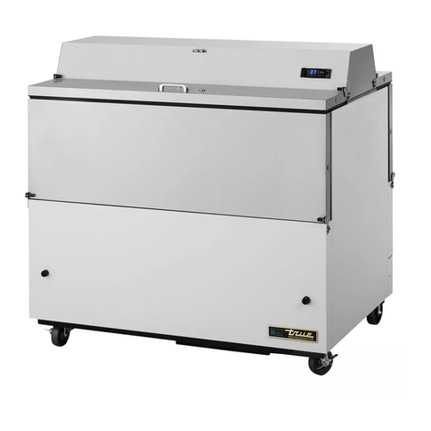
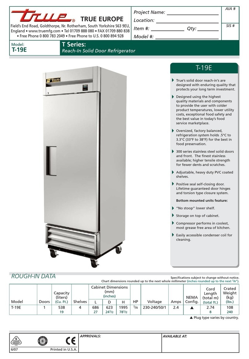
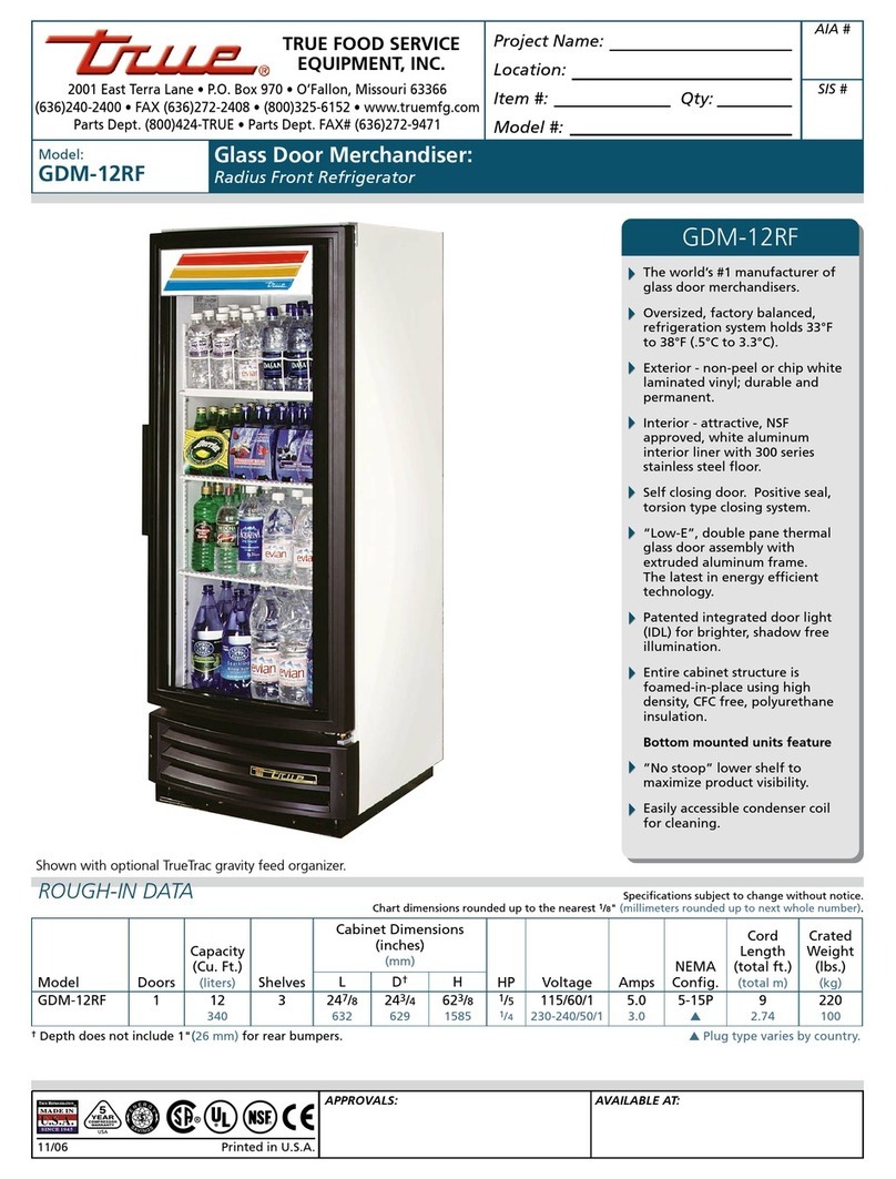
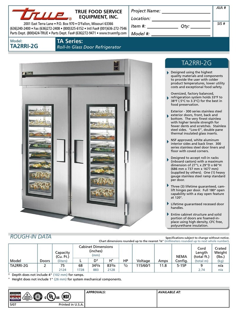
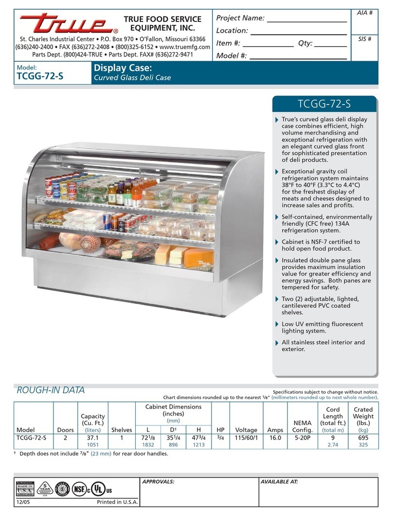
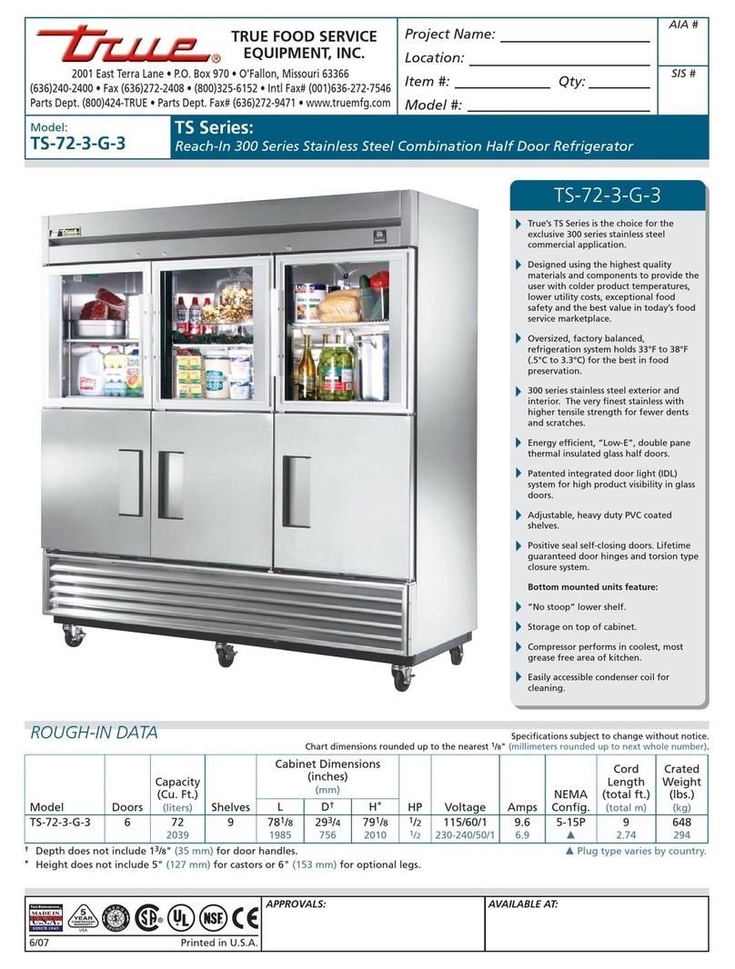
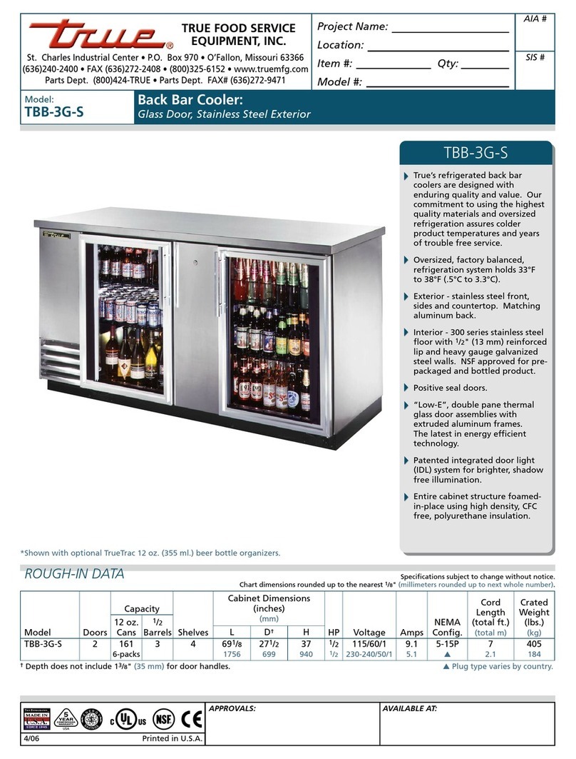
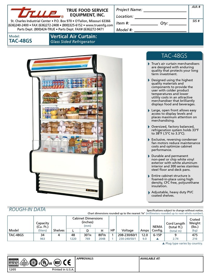
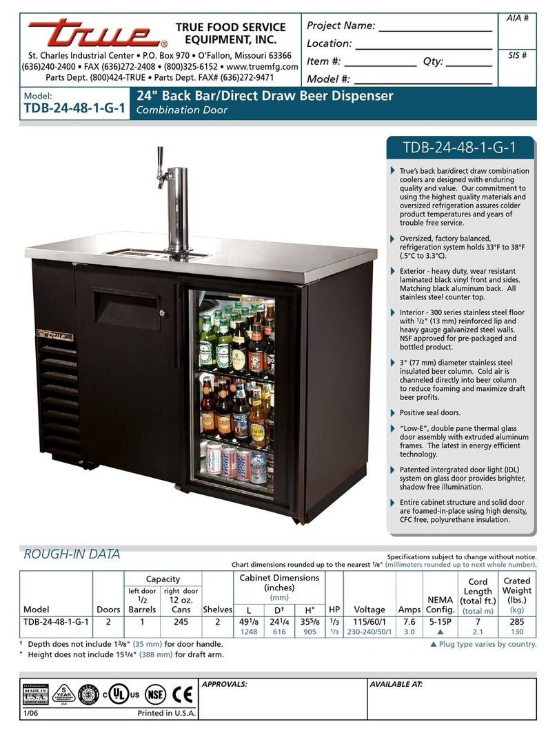
True TD-50-18-S-LT User manual

............ www.truemfg.com ............
TABLE OF CONTENTS
Safety Information
Safety Precautions 1
Proper Disposal 2
Connecting Electricity 3
Adapter Plugs 3
Installation / Operation Instructions
Ownership 4
Required Tools 4
Uncrating 4
Location 5
Leveling Cabinet 5
Wire Gauge Cart 6
Sealing Cabinet to the floor 7
Electrical Instructions 8
Direct Draw Draft Arm Installation 8-9
Start-up and Light Switch Location 9
Temperature Control Adjustment 10
Shelving & Bin Divider Installation 11
Storage & Handling 11
Temperature/Pressure/Tapping 12
Draft Beer Problems 13
Maintenance, Care & Cleaning
Changing CO2Gas Cylinder 14
Cleaning Bar System 15
Cleaning the Condenser 16
Important Warranty Information 17
Stainless Steel Equipment Care & Cleaning 18-19
Lightbulb Replacement 20
Warranty (U.S.A. and Canada ONLY!) 21
UNDERBAR
REFRIGERATION
CONGRATULATIONS!
You have just purchased the finest commercial
refrigerator available. You can expect many years
of trouble-free operation.
TBB-3G-S
TBB-2
TD-50-18-S-LT
TDD-4
*Spanish, German, French, and Dutch versions included.
TDB-24-48-1-G-1
12/8/10 CR #894417
INSTALLATION MANUAL FOR
UNDERBAR REFRIGERATION
TRUE FOOD SERVICE EQUIPMENT, INC.
2001 East Terra Lane • O’Fallon, Missouri 63366-4434
(636)-240-2400 • FAX (636)-272-2408 • INT'L FAX (636)272-7546 • (800)-325-6152
Parts Department (800)-424-TRUE • Parts Department FAX# (636)-272-9471

............ www.truemfg.com ............
True Food Service Equipment, Inc.

............ www.truemfg.com ............
SAFETY INFORMATION
True Food Service Equipment, Inc.
11
• Thisrefrigeratormustbeproperlyinstalled
andlocatedinaccordancewiththeInstallation
Instructionsbeforeitisused.
• Donotallowchildrentoclimb,standorhang
ontheshelvesintherefrigerator.Theycould
damagetherefrigeratorandseriouslyinjure
themselves.
• Donottouchthecoldsurfacesinthefreezer
compartmentwhenhandsaredamporwet.
Skinmaysticktotheseextremelycoldsurfaces.
• Donotstoreorusegasolineorotherflammable
vaporsandliquidsinthevicinityofthisorany
otherappliance.
• Keepfingersoutofthe“pinchpoint”areas;
clearancesbetweenthedoorsandbetweenthe
doorsandcabinetarenecessarilysmall;becareful
closingdoorswhenchildrenareinthearea.
NOTE: We strongly recommend that any servicing
be preformed by a qualified individual.
• Unplugtherefrigeratorbeforecleaning
andmakingrepairs.
• Settingtemperaturecontrolstothe0position
doesnotremovepowertothelightcircuit,
perimeterheaters,orevaporatorfans.
WARNING!
Use this appliance for its intended purpose as described in this Owner Manual.
This cabinet contains fluorinated greenhouse gas covered by the Kyoto Protocol
(please refer to cabinet's inner label for type and volume,
GWP of 134a= 1,300. R404a= 3,800).
How to Maintain Your lkkkfdls
Unit to Receive the Most Efficient and
Successful Operation
You have selected one of the finest commercial refrigeration units made. It is manufactured
under strict quality controls with only the best quality materials available. Your TRUE cooler when
properly maintained will give you many years of trouble-free service.
SAFETY PRECAUTIONS
When using electrical appliances, basic safety precautions should be followed, including the following:

............ www.truemfg.com ............
True Food Service Equipment, Inc.
SAFETY INFORMATION
2 2
PROPER DISPOSAL OF THE REFRIGERATOR
DANGER!
RISK OF CHILD ENTRAPMENT
USE OF EXTENSION CORDS
NEVER USE AN EXTENSION CORD! TRUE will not warranty any refrigerator that has been connected to an extension cord.
Childentrapmentandsuffocationarenotproblems
ofthepast.Junkedorabandonedrefrigeratorsare
stilldangerous…eveniftheywillsitfor“justafew
days.”Ifyouaregettingridofyouroldrefrigerator,
pleasefollowtheinstructionsbelowtohelp
preventaccidents.
Before You Throw Away Your Old Refrigerator or Freezer:
• Takeoffthedoors.
• Leavetheshelvesinplacesothatchildrenmay
noteasilyclimbinside.
Refrigerant Disposal
Youroldrefrigeratormayhaveacoolingsystem
thatuses“OzoneDepleting”chemicals.Ifyou
arethrowingawayyouroldrefrigerator,makesure
therefrigerantisremovedforproperdisposalby
aqualifiedservicetechnician.Ifyouintentionally
releaseanyrefrigerantsyoucanbesubjecttofines
andimprisonmentunderprovisionsofthe
environmentalregulations.

Thepowercordofthisapplianceisequipped
witha3-prong(grounding)plugwhichmates
withastandard3-prong(grounding)walloutlet
tominimizethepossibilityofelectricshock
hazardfromthisappliance.
Havethewalloutletandcircuitcheckedbya
qualifiedelectriciantomakesuretheoutletis
properlygrounded.
Iftheoutletisastandard2-prongoutlet,itis
yourpersonalresponsibilityandobligationto
haveitreplacedwiththeproperlygrounded
3-prongwalloutlet.
Therefrigeratorshouldalwaysbepluggedinto
it’sownindividualelectricalcircuit,whichhas
avoltageratingthatmatchestheratingplate.
Thisprovidesthebestperformanceandalsoprevents
overloadingbuildingwiringcircuitswhichcould
causeafirehazardfromoverheatedwires.
Neverunplugyourrefrigeratorbypullingonthe
powercord.Alwaysgripplugfirmlyandpull
straightoutfromtheoutlet.
Repairorreplaceimmediatelyallpowercordsthat
havebecomefrayedorotherwisedamaged.Donot
useacordthatshowscracksorabrasiondamage
alongitslengthorateitherend.
Whenremovingtherefrigeratorawayfromthe
wall,becarefulnottorolloverordamagethe
powercord.
HOW TO CONNECT ELECTRICITY
Do not, under any circumstances, cut or remove the third (ground) prong from the power cord.
For personal safety, this appliance must be properly grounded.
WARNING!
USE OF ADAPTER PLUGS
NEVER USE AN ADAPTER PLUG! Because of potential safety hazards under certain conditions, we strongly recommend against
the use of an adapter plug.
............ www.truemfg.com ............
SAFETY INFORMATION
True Food Service Equipment, Inc.
33
115/60/1
NEMA-5-20R
115/208-230/1
NEMA-14-20R
115/60/1
NEMA-5-15R
208-230/60/1
NEMA-6-15R
NEMA plug configurations
T-Series and GDM Freezers
Spec Series same as T-Series
Back Bar
Milk Coolers
TSSU
TPP
TWT
TUC
TRCB
T-Series and GDM Refrigerators
Double Duty, Single Duty, Curved Glass
Horizontal Freezers
GDIM
TAC (Air Curtain)
(North America Use Only!)
NEMAplugs
TRUEusesthesetypesofplugs.
Ifyoudonothavetherightoutlet
haveacertifiedelectricianinstall
thecorrectpowersource.

............ www.truemfg.com ............
True Food Service Equipment, Inc.
INSTALLATION / OPERATION INSTRUCTIONS
4 4
Toinsurethatyourunitworksproperlyfromthe
firstday,itmustbeinstalledproperly.Wehighly
recommendatrainedrefrigerationmechanicand
electricianinstallyourTRUEequipment.Thecost
ofaprofessionalinstallationismoneywellspent.
BeforeyoustarttoinstallyourTRUEunit,
carefullyinspectitforfreightdamage.Ifdamage
isdiscovered,immediatelyfileaclaimwiththe
deliveryfreightcarrier.
TRUE is not responsible for damage incurred during shipment.
OWNERSHIP
• AdjustableWrench
• PhillipsHeadScrewdriver
• Level
REQUIRED TOOLS
Thefollowingprocedureisrecommendedfor
uncratingtheunit:
A. Removetheouterpackaging,(cardboard
andbubblesorstyrofoamcornersandclear
plastic).Inspectforconcealeddamage.Again,
immediatelyfileaclaimwiththefreightcarrier
ifthereisdamage.
B. Moveyourunitasclosetothefinallocationas
possiblebeforeremovingthewoodenskid.
C. Removedoorbracketonswingingglassdoor
models(seeimage1-2).
Note:Keys for coolers with door locks are located in
warranty packets.
UNCRATING
INSTALLATION / OPERATION INSTRUCTIONS
1
2
REMOTE UNITS (This section applies to remotes only!)
• Remotecabinetsmustbeorderedasremote.
Wedonotrecommendconvertingfora
standardselfcontainedtoremotesystem.
• Allremotecabinetsmustbehardwired.
• Nocastorsavailable.
• Allremotecabinetscomestandardusing404A
refrigerant.
• Allremoteunitscomestandardwithexpansion
valve,liquidlinesolenoid,heatedcondensate
pan,anddefrosttimerwhenapplicable.
• ContactTrueTechnicalServiceforBTU
requirements.
• Nowiringnecessarybetweencabinet
andcondensingunit.
• Allremotecondensingunitspurchased
fromTRUEare208/230voltssinglephase.
If you have any questions regarding this section,
please call TRUE at 1-(800)-325-6152.

............ www.truemfg.com ............
INSTALLATION / OPERATION INSTRUCTIONS
True Food Service Equipment, Inc.
55
TOOLS REQUIRED:
•Phillipsscrewdriver
•3/8”socketor3/8”wrench
A. Useaphillipsscrewdiverandremovefour
screwsfromtheL-bracketconnectedtheunit
tothewoodskid(seeimage1).Thenusea3/8”
socketorwrenchandremovetheL-bracket
fromtheunit(seeimage2).
Whenliftingunitdonotusethecountertopas
aliftingpoint.Alsoremembertoleavecabinet
uprightfor24hoursbeforeplugging
intopowersource.
B. Removeskidbyunscrewingallbaserailanchor
brackets.Placeskidtotheside.
C. Carefullyuprightcabinet.
LOCATING
(Image 1)
Removing
bracket from
skid.
(Image 2)
Removing
bracket from
cabinet.
A. Setunitinitsfinallocation.Besurethere
isadequateventilationinyourroom.Under
extremeheatconditions,(100°F+,38°C+),
youmaywanttoinstallanexhaustfan.
Warning
Warranty is void if ventilation is insufficient.
B. ProperlevelingofyourTRUEcooleriscritical
tooperatingsuccess(fornon-mobilemodels).
Effectivecondensateremovalanddoor
operationwillbeeffectedbyleveling.
C. Thecoolershouldbeleveledfronttoback
andsidetosidewithalevel.
D. Ensurethatthedrainhoseorhosesare
positionedinthepan.
E. Freeplugandcordfrominsidethelowerrear
ofthecooler(donotplugin).
F. Theunitshouldbeplacedcloseenoughtothe
electricalsupplysothatextensioncordsare
neverused.
Warning
Compressor warranties are void if the unit is more than 7 ft.
(2.1m) from plug-in connection or an extension cord is used
to connect unit to a power supply.
LEVELING

............ www.truemfg.com ............
True Food Service Equipment, Inc.
6 6
CONDUCTORS AND CIRCUITS
Wire Gauge for 2% Voltage Drop in Supply Circuits.
115 Volt Distance In Feet To Center of Load
Amps 20 30 40 50 60 70 80 90 100 120 140 160
2 14 14 14 14 14 14 14 14 14 14 14 14
3 14 14 14 14 14 14 14 14 14 14 14 12
4 14 14 14 14 14 14 14 14 14 12 12 12
5 14 14 14 14 14 14 14 12 12 12 10 10
6 14 14 14 14 14 14 12 12 12 10 10 10
7 14 14 14 14 14 12 12 12 10 10 10 8
8 14 14 14 14 12 12 12 10 10 10 8 8
9 14 14 14 12 12 12 10 10 10 8 8 8
10 14 14 14 12 12 10 10 10 10 8 8 8
12 14 14 12 12 10 10 10 8 8 8 8 6
14 14 14 12 10 10 10 8 8 8 6 6 6
16 14 12 12 10 10 8 8 8 8 6 6 6
18 14 12 10 10 8 8 8 8 8 8 8 5
20 14 12 10 10 8 8 8 6 6 6 5 5
25 12 10 10 8 8 6 6 6 6 5 4 4
30 12 10 8 8 6 6 6 6 5 4 4 3
35 10 10 8 6 6 6 5 5 4 4 3 2
40 10 8 8 6 6 5 5 4 4 3 2 2
45 10 8 6 6 6 5 4 4 3 3 2 1
50 10 8 6 6 5 4 4 3 3 2 1 1
Wire Gauge for 2% Voltage Drop in Supply Circuits.
230 Volt Distance In Feet To Center of Load
Amps 20 30 40 50 60 70 80 90 100 120 140 160
5 14 14 14 14 14 14 14 14 14 14 14 14
6 14 14 14 14 14 14 14 14 14 14 14 12
7 14 14 14 14 14 14 14 14 14 14 12 12
8 14 14 14 14 14 14 14 14 14 12 12 12
9 14 14 14 14 14 14 14 14 12 12 12 10
10 14 14 14 14 14 14 14 12 12 12 10 10
12 14 14 14 14 14 14 12 12 12 10 10 10
14 14 14 14 14 14 12 12 12 10 10 10 8
16 14 14 14 14 12 12 12 10 10 10 8 8
18 14 14 14 12 12 12 10 10 10 8 8 8
20 14 14 14 12 10 10 10 10 10 8 8 8
25 14 14 12 12 10 10 10 10 8 8 6 6
30 14 12 12 10 10 10 8 8 8 6 6 6
35 14 12 10 10 10 8 8 8 8 6 6 5
40 14 12 10 10 8 8 8 6 6 6 5 5
50 12 10 10 8 6 6 6 6 6 5 4 4
60 12 10 8 6 6 6 6 6 5 4 4 3
70 10 10 8 6 6 6 5 5 4 4 2 2
80 10 8 8 6 6 5 5 4 4 3 2 2
90 10 8 6 6 5 5 4 4 3 3 1 1
100 10 8 6 6 5 4 4 3 3 2 1 1
INSTALLATION / OPERATION INSTRUCTIONS
............ www.truemfg.com ............
True Food Service Equipment, Inc.
77
Step 1 - Position Cabinet
Allowoneinchbetweenthewallandrearof
therefrigeratedBarEquipmenttoassureproper
ventilation.ForGlass&PlateChillers/Frosters
3inchesbetweenthewallandrearofthe
cabinetwillassureproperventilation.
Step 2 - Level Cabinet
Cabinetshouldbelevel,sidetosideandfrontto
back.Placeacarpenter’slevelintheinteriorfloor
infourplaces:
A. Positionlevelintheinsideflooroftheunit
nearthedoors.(Levelshouldbeparalleltocabinet
front).Levelcabinet.
B. Positionlevelattheinsiderearofcabinet.
(Againlevelshouldbeplacedparalleltocabinet
back).
C. PerformsimilarprocedurestostepsA&Bby
placingtheleveloninsidefloor(leftandright
sides-paralleltothedepthofthecooler).Level
cabinet.
Step 3
Drawanoutlineonthebaseonthefloor.
Step 4
Raiseandblockthefrontsideofthecabinet.
Step 5
Applyabeadof“NSFApprovedSealant”,(seelist
below),toflooronhalfinchinsidetheoutlinedrawn.
Thebeadmustbeheavyenoughtosealtheentire
cabinetsurfacewhenitisdownonthesealant.
Step 6
Raiseandblocktherearofthecabinet
Step 7
Applysealantonfloorasoutlined
inStep5onotherthreesides.
Step 8
Examinetoseethatcabinetissealedtofloor
aroundentireperimeter.
Note:
Asphaltfloorsareverysusceptibletochemical
attack.Alayeroftapeonthefloorpriorto
applyingthesealantwillprotectthefloor.
NSF Approved Sealants:
1.MinnesotaMining#ECU800Caulk
2.MinnesotaMining#ECU2185Caulk
3.MinnesotaMining#ECU1055Bead
4.MinnesotaMining#ECU1202Bead
5.ArmstrongCork-RubberCaulk
6.ProductsResearchCo.#5000RubberCaulk
7.G.E.SiliconeSealer
8.DowCorningSiliconeSealer
SEALING CABINET TO FLOOR
INSTALLATION / OPERATION INSTRUCTIONS
............ www.truemfg.com ............
True Food Service Equipment, Inc.
8 8
INSTALLATION / OPERATION INSTRUCTIONS
A. Beforeyournewunitisconnectedtoapower
supply,checktheincomingvoltagewitha
voltmeter.Ifanythinglessthan100%ofthe
ratedvoltageforoperationisnoted,correct
im mediately.
B. Allunitsareequippedwitha7ft.(2.1m)service
cord,andmustbepoweredatproperoperating
voltageatalltimes.Refertocabinetdataplate
forthisvoltage.
TRUErecommendsthatasoleusecircuitbe
dedicatedfortheunit.
WARNING
Compressor warranties are void if compressor burns out due
to low voltage.
WARNING
Power supply cord ground should not be removed!
NOTE
To reference wiring diagram - Remove front louvered grill,
wiring diagram is positioned on the inside cabinet wall.
ELECTRICAL INSTRUCTIONS
Ondirectdraws,thedrainislocatedatthe
frontofthecabinet.Toplumbinthedrain,
connect3⁄4"(2cm)P.V.C.pipetothe3⁄4"(2cm)
barbedfittingsupplieswiththeunit.
CO2PRESSURE
Mobiletapsters,toretaincompletemobility,
theCO2tank(uptofivepoundsinsize)can
beplacedinsidethecooler(strapholders
furnished).
CAUTION
Filled CO2tanks are potentially dangerous because
of the pressure they contain. If you are unfamiliar
with their use or the use of the CO2regulator, seek
information from your local distributor, or your local
beverage man before proceeding.
INSTALL DRAFT ARM
Placerubberwasheroverdraftarmmounting
holesincabinet,putbeerlineconnector
downthroughhole.Next,securedraftarm
withfourscrews.(Seeimages1-6)
DIRECT DRAW DRAFT ARM INSTALLATION
CONTINUED ON
NEXT PAGE...
Draft arm install contents.
(Draft arm not shown)
Beer line
connector.
Thread beer line connector to draft arm and secure draft
arm to cabinet with rubber gasket under the draft arm.
Thread
beer draft
arm handle
onto the
draft arm.
1
2
3 4 5
6

INSTALL DRAFT ARM continued...
Insertairhose(oneinchplastictube)
indraftarm,beingcarefulnottodisturb
insulation.Removetopcoverofdraft
armandattachairhosecliptothe
insulatingsleeveatthetopofthedraft
arm.Replacetopcover.Theairhose
clipwillassurethatthehoseremains
inproperplaceatalltimes,keeping
thebeerfaucetcold.(Seeimage7-9)
............ www.truemfg.com ............
True Food Service Equipment, Inc.
99
INSTALLATION / OPERATION INSTRUCTIONS
DIRECT DRAW DRAFT ARM INSTALLATION
CONTINUED...
A. Thecompressorisreadytooperate.Pluginthe
cooler.
B. TemperaturecontrolsetatNo.4positiongives
refrigeratorsanapproximatetemperatureof
35°Fandglasschillerfrostershaveanapproximate
temperatureof0°F.Allowunittofunctionseveral
hours,completelycoolingcabinetbeforechanging
thecontrolsetting.
C. Excessivetamperingwiththecontrolcouldlead
toservicedifficulties.Shoulditeverbecome
necessarytoreplacetemperaturecontrol,be
sureitisorderedfromyourTRUEdealeror
recommendedserviceagent.
D. GoodairflowinyourTRUEunitiscritical.Be
carefultoloadproductsothatitneitherpresses
againstthebackwall,norcomeswithinfourinches
oftheevaporatorhousing.Refrigeratedairoff
thecoilmustcirculatedownthebackwall.
LIGHT SWITCH LOCATION:
The switch is located on the front of the evaporator housing
toward the front of the cabinet. Open the front doors and the
switch will be visible close to the ceiling the cabinet.
NOTE
If the unit is disconnected or shut off, wait five minutes
before starting again.
RECOMMENDATION
Before loading product we recommend you run your TRUE
unit empty for two to three days. This allows you to be sure
electrical wiring and installation are correct and no shipping
damage has occurred. Remember, our factory warranty does
not cover product loss!
REPLACEMENT PARTS
TRUE maintains a record of the cabinet serial number for
your cooler. If at any time during the life of your cooler, a
part is needed, you may obtain this part by furnishing the
model number and serial number to the company from whom
you purchased the cooler. Call Toll-Free: (800)-424-TRUE
(Direct to Parts Department). (800)-325-6152 (U.S.A.
& Canada only) or call: (636)-240-2400.
STARTUP
7 8 9

............ www.truemfg.com ............
True Food Service Equipment, Inc.
10 10
TERMS:
Cut-out-Temperaturesensed
bythecontrollerthatshutsthe
compressoroff.
Cut-in-Temperaturesensedby
thecontrollerthatturnsthe
compressoron.
REQUIRED TOOLS
• PhillipsHeadScrewdriver
• 5/64"or2mmAllenWrench
• T-7TorxWrench
__________ STEP 1 ___________
Unplugthecooler.
__________ STEP 2 ___________
Removethescrewsthatsecure
thetemperaturecontroltothe
insetbox.
__________ STEP 3 ___________
Pulloutgentlyfromcabinet.
__________ STEP 4 ___________
Forhighelevationinstallations,
itmaybenecessaryto"warm-
up"thesetpoints.Tomake
theadjustment,insertthe
appropriatetoolineach
adjustmentscrewandturn1/4
ofarevolutionclockwise(tothe
right).Thisprocedurewilladjust
boththecut-inandcut-outabout
2°Fwarmer.
__________ STEP 5 ___________
Makesuretoreconnectthe
pinkwiretotheproperspade
terminalwhenreinstalling.
NOTE:
Mechanical temperature
controllers are affected when
functioning at high altitude. The
cut-in and cut-out
temperatures will be colder than
when the controller functions
closer to sea level
Danfoss Temperature Control (High Altitude Adjustment Only!)
Cut-outAdjustmentScrewAllen(5/64"
or2mm)(clockwiseforwarmer)
Cut-inAdjustmentScrewTorx(T-7)
(clockwiseforwarmer)
CompressorConnection(pink)
TEMPERATURE CONTROL ADJUSTMENT FOR
HIGH ALTITUDE ONLY!
INSTALLATION / OPERATION INSTRUCTIONS
............ www.truemfg.com ............
True Food Service Equipment, Inc.
11 11
O
F
F
9
8
7
6
5
4
3
2
1
SHELVING and BIN DIVIDER INSTALLATION /
OPERATION
SHELF INSTALLATION:
A.Hookshelfclipsontoshelfstandards.
B.Positionallfourshelfclipsequalindistance
fromthefloorforflatshelves.
C.Shelvesareorientedsothatcrosssupportbars
arefacingdown.
D.Placeshelvesonshelfclipsmakingsureall
cornersareseatedproperly.
HORIZONTAL BOTTLE COOLER BIN DIVIDER
INSTALLATION:
Horizontalbottlecoolersareshippedwithbin
dividersinplace.Ifitisnecessarytoadjustspacing
thefollowingprocedureisrecommended.
A.Dividersarespringloaded-pushdivider
towardsrearofthecoolertoreleasefromfront
grommetedholes.
B.Lineupdividerfrontpegswithdesiredholesand
punchthroughinteriortapeliningofbothtop
andbottomholes-bottompegfirst(frontholes
aretapedovertoimproveinsulationvalues).
C. Removedividerfromthefrontholesandlineup
regularandspringloadedrearpegswithholes
inlinewiththosedesiredinfront.Insertasfar
aspossibleandmaneuverfrontpegsinplace.
SHELF INSTALLATION
BIN DIVIDER INSTALLATION
NOTE:
Divider
positioned
infrontof
mechanical
boxrequires
specificnotch
cutout.
Draftbeershouldbetreatedasafoodproduct.In
mostinstancesdraftbeerisnotpasteurized.Itis
veryimportantthatyoustoreandhandleitproperly.
Followthesestepstoensurethehighestqualityand
consumersatisfaction.
• Draftbeershouldbeimmediatelystoredina
refrigeratedcabinet.
• Draftbeerproductshavearecommendedshelf
life.Ifyouhavequestionsregardingtheshelflife
ofanyofyourdraughtproducts,pleaseconsult
withyoursupplyingdepotorrespectiveBrewer
representative.
• Kegsshouldbestoredseparatelyfromfood
products.Ifyourcoolerisusedtorefrigerate
draughtandfoodproducts,itisveryimportant
thatthefoodnotbestorednearoronthekegs.
• Kegstorageanddispensingareasshouldbekept
cleantopreventanypossibilityofcontaminating
yourdraughtproducts.
STORAGE AND HANDLING
Shelf
Clip
Shelf
Shelf
Pillaster
(I-beam)
Shelf
Standards
INSTALLATION / OPERATION INSTRUCTIONS
............ www.truemfg.com ............
True Food Service Equipment, Inc.
12 12
Dispensing pressures differ according to:
• Thetypeofdraftdispensingsystem
• Thelengthofdraftdispensingline
• Theactualproduct-somerequiremore,
some require less
• Thetemperatureoftheproduct
• Thepressurizingagent:airpressure,
CO2or special blended gases.
PRESSURE
• Correcttemperatureisakeyfactortoconsiderin
storinganddispensingdraftbeer.Toocoolortoowarm
maycauseflavorloss,offtasteanddispensingproblems.
Helpful Hints on Controlling Temperature
• Keepathermometerhandy
• Monitortemperatureofdraftinyourcooler
andatthetap
• Keepcoolerdoorclosedasmuchaspossible
toavoidtemperaturefluctuation
• Regularmaintenanceofrefrigerationequipment
isrecommended
TEMPERATURE
Helpful Hints On Maintaining The Correct Pressure:
• Knowwhichpressurizingagentto
useonwhichproductandwhy.
• Monitoryourregulatorstoensure
appliedpressureremainsconstant
• Keepequipmentingoodrepair
Donotagitatethekegsunnecessarily.Ifexcessive
agitationoccursallowkegstosettlefor1to2hours
beforetapping.
Priortotappingthekeg,ensurethatallbeerfaucetin
theservinglocationareintheoffposition.Completely
removethedustcover(identificationcap)fromthekeg.
TAPPING
This instruction is TRUE’s
recommended procedure for installing
a remote CO2container.
REQUIRED TOOLS
• Pliers
• Power Drill
• Silicone Sealer
• Drill bit, 1/2”
STEP 1
Remove black knockout plug with a
pair of pliers.
NOTE:
Knockout plug for CO2 line can be
locate in two different areas. View
diagram to locate these two areas.
STEP 2
Use drill and bit to bore hole straight
back through wall into compressor
compartment.
STEP 3
Snake CO2 line through hole down
and around exiting behind rear castor
underneath rear grill.
STEP 4
Seal hole around CO2 line with
silicone sealer to prevent cold air
leakage.
TDD-1 CO2KNOCK-OUT
O
F
F
9
8
7
6
5
4
3
2
Knockout Plug
can be located at
either location.
INSTALLATION / OPERATION INSTRUCTIONS
............ www.truemfg.com ............
True Food Service Equipment, Inc.
13 13
Flat Beer - Description: Foamy head
disappears quickly. Beer lacks usual zestful
brewery fresh flavor.
• CO2turnedoffwhennotinuse.
• Contaminatedairsource(associated
withcompressedair).
• Greasyglasses.
• Notenoughpressure.
• Pressureshutoffduringnight.
• Loosetaporventconnection.
• Sluggishpressureregulator.
• Obstructioninlines.
False Head - Description: Large soap-like
bubbles, head dissolves very quickly.
• Dryglasses.
• Improperpour.
• Pressurerequireddoesnotcorrespond
tobeertemperature.
• Coilsordirectdrawbeerlineswarmer
thanbeerinkeg.
• Smalllinesintolargefaucetshanks.
• Beerdrawnimproperly.
Wild Beer - Description: Beer, when drawn,
is all foam and not enough liquid beer.
• Beerdrawnimproperly.
• Faucetinbadorworncondition.
• Kinks,dents,twistsorother
obstructionsinline.
• Trapsinbeerlines.
• Beertoowarminkegsorlines.
• Toomuchpressure.
• Creepinggaugecausingtoomuch
pressure.
Cloudy Beer - Description: Beer in the glass
appears hazy. Not clear.
• Dirtyglassorfaucet.
• Beeroverchilled.
• Beertemperaturevarianceinkeg(Beer
mayhavewarmedupatsometime).
• Hotspotsinbeerlines.
• Cuttingbeerthroughfaucet.
• Beerlineinpoorcondition.
• Dirtylines.
• Beerthathasbeenfrozen.
Bad Taste
• Dirtyfaucet.
• Oldordirtybeerlines.
• Failuretoflushbeerlineswithwater
aftereachemptykeg.
• Unsanitaryconditionsatbar.
• Foulairordirtinlines.
• Oilyair;greasykitchenair.
• Temperatureofpackagetoowarm.
• Dryglasses
DRAFT BEER PROBLEMS
To minimize draft beer problems, always follow the recommended
instructions for temperature and CO2pressures from your beer supplier.
INSTALLATION / OPERATION INSTRUCTIONS
............ www.truemfg.com ............
True Food Service Equipment, Inc.
14 14
Follow these instructions at ALL times when you
replace a CO2 gas cylinder:
1. Closecylinderat"A".
2. Removetap"D"frombarrel.Pullpressure
releaseringonbodyoftaptoreleasepressure
remaininginline.(donotclose"C")
3. Removeorloosenregulatorkey"B"byturning
counterclockwise.
4. Removeregulatorfromusedcylinderat"E".
5. Removedustcapfromnewgascylinderat
"E"andcleardustfromoutletbyopeningand
closingvalve"A"quicklyusingappropriate
wrench.
6. Attachregulatortonewcylinderat"E".(use
newfiber/plasticwasher,ifrequired).
7. Openvalve"A"alltheway.
8. Closevalve"C".
9. Adjustregulatorkey"B"byturningclockwise
tosetpressure.(checksettingbyopening"C"
andpullingandreleasingthering"F"onthe
pressurereleasevalveonthebodyofthetap)
10.Tapbarrelat"D"withvalve"C"open.
NOTE
Don't lay CO2 cylinders flat.
Don't drop CO2 cylinders.
It requires 1/2 pound CO2 to dispense 1/2 barrel of beer
at 38˚F with 15 pounds pressure on barrel.
PRESSURE ADJUSTMENT ON CO2
REGULATOR
Increasing Pressure:
1. Closeregulatorshut-off"C".
2. Turnregulatorkey"B"clockwiseandmake
setting.
3. Tapgaugeforaccuratereading.
4. Openregulatorshut-off"C"anddrawbeer.
Decreasing Pressure:
1. Closeregulatorshut-off"C".
2. Untapbarrelat"D"andtobleedline,activate
taphandle.Leaveinopenposition.
3. Slowlyopenregulatorshut-off"C"and
simultaneouslyturnregulatorkeycounter-
clockwisetozeroreading.
4. Closeregulatorshut-off"C"andsetpressureby
turningregulatorkeyclockwise.Checksetting
byopeningandclosingvalve"C".
5. Closetaphead"D".(putin"OFF"position)
6. Tapbarrelat"D"andopenregulatorshut-off"C".
CHANGING CO2GAS CYLINDER
A
B
C
D
E
F
MAINTENANCE, CARE & CLEANING

............ www.truemfg.com ............
True Food Service Equipment, Inc.
15 15
Draughtdispensers,regardlessofdesign,mustbe
cleanedatleasteverytwoweeks.Flushingyour
draughtdispenserwithwateronlyisnotenough.
Note: Use cleaners approved by your beer supplier and
follow their instructions. If you are using the cleaning
kit purchased from TRUE follow these instructions:
Exacting cleanliness should be constantly maintained
in your dispenser so that your draught beer will be at
its best when served. Although the beer in the barrel is
in excellent condition, it can become less satisfying as
it is drawn through the beer line and faucet if they are
not kept clean.
Prepare Solution:
• Add1/2ounce(19grams)oflinecleaning
powdertoeachquartofwater,coldorwarm.
Cleaning:
1. Disconnecttapfrombarrel.Removebeerfaucet
withspannerwrenchunscrewhandleand
removevalveassembly(fig.1).
2. Puttapandfaucetpartsinabucketwith
cleaningsolutiontosoak.
3. Usesmallbrushtocleanbeerfaucetparts
(fig.2).
4. Rinsepartsthoroughly.
5. FillpumpbottlewithDBKsolution.
6. Attachhosefrompumpbottletobeercolumn
tapoutlet(besurerubbergasketisinplaceto
preventleakage)-allowtaptodraininbucket
(fig.3).
7. Pumpsolution(2-3timesfrombottlethrough
thelineuntilitstartstoflowoutthebeerline.
Wait 10 minutes while cleaning solution works
on the lines.
8. Pumpexcesssolutionthroughlines.
9. Rinsebucket,pumpbottleandhosethoroughly
withcleancoolwater.
10.Fillpumpbottlewithcleancoolwaterand
pumpthroughlinesuntilwaterrunsclear.
11. Whencrystalclearwatercomesthrough,you're
readytoassembleandreattachfaucetandre-tap
thebarrel.
12.Drawthewaterfromthebeerline;nowyou're
readytoservebreweryfresh,goldenbeer.
NOTE
Keeping your dispenser and all its parts clean and
odor free will help you to serve beautiful foam topped
glasses of delicious satisfying draught beer.
CLEANING BAR SYSTEM
fig.1 fig.2 fig.3
Beer Tap Cleaning Kit
Required Tools
linecleaning
powder Spanner
wrench
Brush
Pumpbottle
andtub Bucketand
freshwater
MAINTENANCE, CARE & CLEANING

............ www.truemfg.com ............
True Food Service Equipment, Inc.
16 16
MAINTENANCE, CARE & CLEANING
CLEANING THE CONDENSER COIL
When using electrical appliances, basic safety precautions should be followed, including the following:
T
M
C
TRUE
REQUIREDTOOLS
•PhillipsScrewdriver
•StiffBristleBrush
•AdjustableWrench
STEP 1
Disconnectpowertounit.
STEP 2
Takeofflowergrillassemblybyremovingall
screws.
STEP 3
Removeboltsanchoringcompressorassembly
toframerailsandcarefullyslideout.(tube
connectionsareflexible)
STEP 4
Cleanoffaccumulateddirtfromcondensingcoil
withastiffbristlebrush.
STEP 5
Liftcardboardcoverabovefanatplasticplugsand
carefullycleancondensercoilandfanblades.
STEP 6
Afterbrushingcondensercoilvacuumdirtfrom
coil,andinteriorfloor.
STEP 7
Replacecardboardcover.Carefullyslide
compressorassemblybackintopositionand
replacebolts.
STEP 8
Reinstalllouverassemblyontounitwith
appropriatefastenersandclips.Tightenallscrews.
STEP 9
Connectunittopowerandchecktoseeif
condenserisrunning.

............ www.truemfg.com ............
True Food Service Equipment, Inc.
17 17
Condensers accumulate dirt and require cleaning every 30 days. Dirty condensers result in
compressor failure, product loss, and lost sales... which are not covered by warranty.
If you keep the Condenser clean you will minimize your service expense and lower your electrical costs. The
Condenser requires scheduled cleaning every thirty days or as needed.
Air is pulled through the Condenser continuously, along with dust, lint, grease, etc.
A dirty Condenser can result in NON-WARRANTEED part & Compressor Failures, Product Loss, and Lost Sales.
Proper cleaning involves removing dust from the Condenser. By using a soft brush, or vacuuming the Condenser
with a shop vac, or using CO2, nitrogen, or pressurized air.
If you cannot remove the dirt adequately, please call your refrigeration service company.
On most of the reach-in units the condenser is accessible in the rear of the unit. You must remove the cabinet grill
to expose the Condenser.
The Condenser looks like a group of vertical fins. You need to be able to see through the condenser for the unit to
function at maximum capacity. Do not place filter material in front of condensing coil. This material blocks air-
flow to the coil similar to having a dirty coil.
THE CLEANING OF THE CONDENSER IS NOT
COVERED BY THE WARRANTY!
HOW TO CLEAN THE CONDENSER:
1. Disconnect the electrical power to the unit.
2. Remove the louvered grill.
3. Vacuum or brush the dirt, lint, or debris from the finned condenser coil.
4. If you have a significant dirt build up you can blow out the condenser with compressed air. (CAUTION
MUST BE USED to avoid eye injury. Eye protection is recommended.)
5. When finished be sure to replace the louvered grill. The gill protects the condenser.
6. Reconnect the electrical power to the unit.
If you have any questions, please call TRUE Manufacturing at 636-240-2400 or 800-325-6152 and ask for the
Service Department. Service Department Availability Monday-Friday 7:30 a.m. to 5:30 p.m.
and Saturday 7:45 a.m. to 11:45 a.m. CST.
MAINTENANCE, CARE & CLEANING
Condensing Unit
Airflow
Condenser
IMPORTANT WARRANTY INFORMATION

............ www.truemfg.com ............
True Food Service Equipment, Inc.
18 18
MAINTENANCE, CARE & CLEANING
CAUTION: Do not use any steel wool, abrasive or chlorine based products to clean stainless steel surfaces.
Stainless Steel Opponents
Therearethreebasicthingswhichcanbreakdownyourstainlesssteel’spassivitylayerandallow
corrosiontorearitsuglyhead.
1)Scratchesfromwirebrushes,scrapers,andsteelpadsarejustafewexamplesofitemsthatcanbe
abrasivetostainlesssteel’ssurface.
2)Depositsleftonyourstainlesssteelcanleavespots.Youmayhavehardorsoftwaterdependingon
whatpartofthecountryyoulivein.Hardwatercanleavespots.Hardwaterthatisheatedcanleave
depositsiflefttosittoolong.Thesedepositscancausethepassivelayertobreakdownandrustyour
stainlesssteel.Alldepositsleftfromfoodpreporserviceshouldberemovedassoonaspossible.
3)Chloridesarepresentintablesalt,food,andwater.Householdandindustrialcleanersaretheworst
typeofchloridestouse.
8 steps that can help prevent rust on stainless steel:
1. Using the correct cleaning tools
Usenon-abrasivetoolswhencleaningyourstainlesssteelproducts.Thestainlesssteel’spassivelayer
willnotbeharmedbysoftclothsandplasticscouringpads.Step2tellsyouhowtofindthepolishingmarks.
2. Cleaning along the polish lines
Polishinglinesor“grain”arevisibleonsomestainlesssteels.Alwaysscrubparalleltovisiblelinesonsome
stainlesssteels.Useaplasticscouringpadorsoftclothwhenyoucannotseethegrain.
3. Use alkaline, alkaline chlorinated or non-chloride containing cleaners
Whilemanytraditionalcleanersareloadedwithchlorides,theindustryisprovidinganeverincreasingchoice
ofnon-chloridecleaners.Ifyouarenotsureofyourcleaner’schloridecontentcontactyourcleanersupplier.
Iftheytellyouthatyourpresentcleanercontainschlorides,askiftheyhaveanalternative.Avoidcleaners
containingquaternarysaltsastheycanattackstainlesssteel,causingpittingandrusting.
4. Water Treatment
Toreducedeposits,softenthehardwaterwhenpossible.Installationofcertainfilterscanremovecorrosive
anddistastefulelements.Saltsinaproperlymaintainedwatersoftenercanbetoyouradvantage.Contacta
treatmentspecialistifyouarenotsureoftheproperwatertreatment.
5. Maintaining the cleanliness of your food equipment
Usecleanersatrecommendedstrength(alkaline,alkalinechlorinatedornon-chloride).Avoidbuild-upofhard
stainsbycleaningfrequently.Whenboilingwaterwithyourstainlesssteelequipment,thesinglemostlikely
causeofdamageischloridesinthewater.Heatinganycleanerscontainingchlorideswillhavethesame
damagingeffects.
6. Rinse
Whenusingchlorinatedcleanersyoumustrinseandwipedryimmediately.Itisbettertowipestanding
cleaningagentsandwaterassoonaspossible.Allowthestainlesssteelequipmenttoairdry.Oxygenhelps
maintainthepassivityfilmonstainlesssteel.
7. Hydrochloric acid (muriatic acid) should never be used on stainless steel
8. Regularly restore/passivate stainless steel
STAINLESS STEEL EQUIPMENT CARE AND CLEANING
This manual suits for next models
4
Table of contents
Other True Refrigerator manuals