TrueClean ToteTilter TTT-05-304A Owner's manual
TOTETILTER™
INSTALLATION / OPERATION / MAINTENANCE

Table of Contents
Introduction . . . . . . . . . . . . . . . . . . . . . . . . . . . . . . . . . . . . . . . . . . . . . . . . . . . . . . . . . . . . . . . . . . . . . . . . . . . . . . . . . . . . . . .3
Safety .............................................................................................4
At a Glance ........................................................................................5
Installation — ToteTilter ...........................................................................6
Installation — Fixed ToteTilter .....................................................................7
Operation..........................................................................................8
Maintenance — Replacing Airlines ................................................................9
Maintenance — Replacing Actuators............................................................ 10
Maintenance — Grease Fittings ..................................................................11
Parts List .........................................................................................12
Troubleshooting..................................................................................13
Customer Notes ..................................................................................14
Warranty .........................................................................................15

3
Introduction
ABOUT
Thank you for purchasing a TrueClean®product.
This manual contains installation, operation, and maintenance
instructions for the TrueClean ToteTilter™. The ToteTilter is designed for
minimal routine maintenance, but care and attention should be given
to the instructions provided in this manual.
All ToteTilters are available with an optional ToteStand™ that can
provide additional functionality. Refer to the ToteStand service manual
for more information.
Do not remove any labeling on any TrueClean product. Immediately
replace any label that is missing.
If, at any point, you have questions or concerns regarding your
ToteTilter, please call 800.654.5635 or 417.831.1411.

4
If, at any point during operation a Danger, Warning, or Caution indication is present, the operator
should immediately take steps to resolve the problem and/or seek assistance from a supervisor.
Safety
IMPORTANT SAFETY INFORMATION
Read this manual before installing, operating, and maintaining this equipment. Failure to read the
manual can result in personal injury and/or equipment damage.
Do not attempt to remove and/or modify any TrueClean products or programming. Doing so can
create unsafe conditions for the operator(s) and/or surrounding persons. Any change to TrueClean
products or programming will void any and all warranties.
Do not place any TrueClean product in an application where general product service ratings are
exceeded. Doing so puts the operator(s) and/or surrounding persons at risk of personal injury and/
or result in equipment damage.
Do not remove any labeling on any TrueClean product. Immediately replace any label that is
missing.
DISCLAIMER OF LIABILITY
TrueClean does not assume responsibility and expressly disclaims liability for loss, damage, or
expenses that arise in any way from the installation, operation, use, or maintenance performed in
accordance with this manual. TrueClean assumes no responsibility for any infringement of patents
or other rights of third parties that may result from use of the module. No license is granted by
implication or otherwise under any patent or patent rights.
TrueClean reserves the right to make changes to the product, specications, or this manual without
prior notice.
DANGER
Indicates an imminently hazardous situation, which if not avoided, has a
high likelihood of resulting in death or serious injury. This symbol is used
in only the most extreme at-risk cases and warrants immediate action.
WARNING
Indicates a potentially hazardous situation, which if not avoided, could
result in death or serious injury. This symbol is used for moderately at-risk
cases and warrants immediate action.
Indicates a potentially hazardous situation, which if not avoided, may
result in minor or moderate injury. This symbol may also be used to alert
against an unsafe operating or maintenance practice.
CAUTION
The words DANGER, WARNING, and CAUTION and their meanings, as used within these
instructions, are listed below:

5
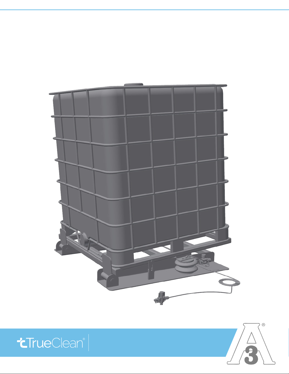
At a Glance
TOTETILTER™
1Tote frame, upper section
2Tote frame, lower section
3Mechanical stop
4Actuator bellows
5Air pressure regulator
6Hand Valve (included)
7Foot Valve (optional)
6
7
2
1
43 5
SIDE VIEW
43 5
1
2
This manual suits for next models
1
Table of contents
Other TrueClean Industrial Equipment manuals


