TrueNAS ES60 Manual

TrueNAS®ES60 Basic Setup Guide
Version 1.92

Contents
1 Introduction ������������������������������������������������������������������������������������������������������������������������ 1
2 ES60 Components ����������������������������������������������������������������������������������������������������������������� 2
2�1 Front Indicators �������������������������������������������������������������������������������������������������������������� 3
2�2 Rear Components and Ports ����������������������������������������������������������������������������������������������� 3
3 Assemble the Rail Kit ������������������������������������������������������������������������������������������������������������� 4
3�1 Separate Cabinet Rails from Rack Rails ���������������������������������������������������������������������������������� 4
3�2 Mount Cabinet Rails ��������������������������������������������������������������������������������������������������������� 4
3�3 Mount the Rack Rails �������������������������������������������������������������������������������������������������������� 4
4 Rack the ES60 ���������������������������������������������������������������������������������������������������������������������� 5
5 Install Drives ����������������������������������������������������������������������������������������������������������������������� 6
5�1 Remove Top Cover ���������������������������������������������������������������������������������������������������������� 6
5�2 Install Drive Trays ������������������������������������������������������������������������������������������������������������ 6
6 Install the Cable Management Arm (CMA) (Optional) ������������������������������������������������������������������� 8
7 Connect Power Cables ���������������������������������������������������������������������������������������������������������� 10
8 Connect SAS Cables �������������������������������������������������������������������������������������������������������������� 11
8�1 X-Series ����������������������������������������������������������������������������������������������������������������������� 11
8�2 R-Series ����������������������������������������������������������������������������������������������������������������������� 12
8�2�1 R20 ������������������������������������������������������������������������������������������������������������������������������������ 12
8�2�2 R40 ������������������������������������������������������������������������������������������������������������������������������������ 13
8�2�3 R50 ������������������������������������������������������������������������������������������������������������������������������������ 14
8�3 M-Series ���������������������������������������������������������������������������������������������������������������������� 15
8�3�1 M40 ����������������������������������������������������������������������������������������������������������������������������������� 15
8�3�2 M50 and M60 ����������������������������������������������������������������������������������������������������������������������� 16
9 Install Bezel (Optional) ��������������������������������������������������������������������������������������������������������� 17
10 Additional Resources ���������������������������������������������������������������������������������������������������������� 17
11 Contacting iXsystems ��������������������������������������������������������������������������������������������������������� 17
Copyright © #### iXsystems, Inc. All rights reserved. All trademarks are the property of their respective owners.

Page 1
1 Introduction
The ES60 is a 4U JBOD with 60 3�5” drive bays, redundant power supplies, and two TrueNAS controllers�
The ES60 requires a rack post depth range between 28�5” and 32” with the Cable Management Arm (CMA), or 36”
without the CMA�
Your system comes with the TrueNAS operating system preloaded�
Review the safety considerations and hardware requirements before installing the ES60 into a rack�
1.1 Safety
1.2 Requirements
1.1.1 Static Discharge
1.1.2 Handling the System
We recommend these tools when installing an R-Series system in a rack:
• #2 Philips head screwdriver
• Flat head screwdriver
• Tape measure
• Level
• 16 standard M5 cage nuts (typically provided with square-hole racks)
We recommend at least two people lift an ES60�
Static electricity can build up in your body and discharge when touching conductive materials� Electrostatic
Discharge (ESD) is harmful to sensitive electronic devices and components� Keep these safety recommendations in
mind before opening the system case or handling non-hot-swappable system components:
• Turn o the system and remove power cables before opening the case or touching internal components.
• Place the system on a clean, hard work surface like a wooden tabletop� Using an ESD dissipative mat can also
help protect the internal components�
• Touch the metal chassis with your bare hand to dissipate static electricity in your body before touching any
internal components, including components not yet installed in the system� Using an anti-static wristband and
grounding cable is another option�
• Store all system components in anti-static bags�
You can nd more preventative tips and details about ESD at https://www�wikihow�com/Ground-Yourself-to-Avoid-
Destroying-a-Computer-with-Electrostatic-Discharge�
Never attempt to lift an ES60 loaded with drives! Install the system in a rack before adding drives, and remove
drives before de-racking the system�
Hold the system from the sides or bottom whenever possible� Always be mindful of loose cabling or connectors,
and avoid pinching or bumping these elements whenever possible�
These instructions use “left” and “right” according to your perspective when facing the front of a system or rack�

Page 2
Accessory kit with 2 IEC C13 to NEMA 5-15P
power cords, 2 IEC C13 to C14 cords, and a set of
velcro cable ties�
ES60 Expansion Shelf
Set of rackmount rails. The rails have a specic
front end, identied by a label visible on the
left above� The front ends of the rails must be
installed facing the front of the rack�
Up to 60 drive trays with installed hard drives,
shipped separately�
Two 3-meter Mini SAS HD to Mini SAS HD cables�
2 ES60 Components
ES60 Bezel
TrueNAS units are carefully packed and shipped with trusted carriers to arrive in perfect condition�
If there is any shipping damage or missing parts, please take photos and contact iXsystems support immediately at
support@ixsystems�com, 1-855-GREP4-iX (1-855-473-7449), or 1-408-943-4100�
Please locate and record the hardware serial numbers on the back of each chassis for quick reference�
Carefully unpack the shipping boxes and locate these components:

Page 3
2.1 Front Indicators
Indicators on the front panel show power, fault, and locate ID� The fault indicator is on during the initial power-on
self-test (POST) or when the TrueNAS software has issued an alert�
1� Power indicator
2� Alarm indicator
3� Locate ID
4� Management port (not used)
5� HD Mini SAS3 connectors
Controller 1
Power Supply 1
Controller 2
Power Supply 2
Light Color and Indication
Green: System on
Amber: Fault
Blue: Locate ID active
ID
2.2 Rear Components and Ports

Page 4
3 Assemble the Rail Kit
3.1 Separate Cabinet Rails from Rack Rails
Each rack rail includes an inner cabinet rail that must be removed� Extend the cabinet rail as shown below until the
white release tab is exposed� Slide the white release tab to the right to release the cabinet rail� Remove the cabinet
rail from the rack rail� Repeat the process for the second rail�
The cabinet rails are mounted on each side of the system� Align the cabinet rail keyholes with the posts on the side
of the chassis� Slide the rail towards the rear of the system until the metal tab clicks and secures the rail in place�
Repeat this process on the other side�
3.2 Mount Cabinet Rails
The ES60 occupies 4U of rack space� The rails mount in the center 2U of that space�
The accessory kit includes cage nuts (for square and round-hole racks), which provide attachment points for rail
screws� Install a cage nut in the 4th hole from the top in the center 2U of rack space� Repeat for all four posts�
The rail ends have Front and Rear stamped on them� Place one rail in the rack with the Front stamp at the front fac-
ing outwards� The Rear stamp goes at the back of the rack� Align the pins on both rail ends with the rack mounting
holes� Make sure the cage nuts line up with the rail holes� Push the pins in to the rack holes until they lock in place�
Use the provided screws to secure the rails to the cage nuts�
3.3 Mount the Rack Rails
M4 Screws
Front Back
3U
2U
Cage Nut Placement
and Rail Alignment

Page 5
4 Rack the ES60
Lift the ES60 with attached cabinet rails and align the cabinet rails with the inside front of the rack rails�
Carefully slide the ES60 forwards into the rack rails until the unit stops (1)� Locate the blue tabs on the inside of the
cabinet rails� Slide the tabs towards the front of the ES60 and hold them in place (2)� Push the chassis into the rack
until the ears are flush with the front of the rack (3)� The thumbscrews on the ears are used to secure the unit in the
rack after drive trays have been installed (4)�
Caution: The ES60 requires two people to safely lift for racking and unracking�

Page 6
5 Install Drives
5.1 Remove Top Cover
Slide the unit out on the rails� Unscrew the cover screws to unlock the top cover (1)� Slide the top cover forwards,
then lift it o (2)�
5.2 Install Drive Trays
TrueNAS systems only support qualied HDs and SSDs. Contact the Sales Team for more drives or replacements.
Adding unqualied drives to the system voids the warranty. Call Support if drives are improperly installed in trays.
To add a new drive into an empty tray, place the tray on a flat surface (1) and push the hard drive into the tray (2)�
Make sure the connector is at the rear of the tray�

Page 7
A standard drive tray installation order simplies support and is strongly recommended: install SSD drives for SLOG
rst, if present. Follow this with SSD drives for L2ARC, if present, then hard drives or SSD drives for data storage.
Install the rst drive tray in the front left drive bay. Install the next drive tray to the right of the rst. Install remain-
ing drive trays to the right across the row. After a row is lled with drives, move back to the next row and start again
with the left bay� A label on the front left of the lid shows the preferred order of drives�
Slide the tray button left to open the latch� Carefully lower the drive tray into a drive bay until the latch begins to
move into place� Push the latch down until it locks into place�
Drive trays mount drives in the chassis� Each drive tray has LEDs that denote its current status�
Light Color / Behavior Status
Solid Blue Normal / Hot Spare
Blinking Blue Activity
Solid Amber Issue / Fault / Identify
Note for Samsung 1643a 2.5” SSDs: Drive tray LED’s only activate during drive activity or drive fault�
For proper air flow and cooling, you must install the entire rst row of drive trays. The top cover must also be in
place when the unit is on�

Page 8
6 Install the Cable Management Arm (CMA) (Optional)
There are two attachment posts on the left rear side of the ES60 for the CMA� Pulling the units lightly out of the rack
can make these posts more accessible� Align the holes on the CMA chassis bracket with the posts� Slide the cable
management arm forwards and pull the lever on the latch upwards to lock the bracket into place�
Locate the end of the flex housing with exposed pins. Un-clip and open the two tabs closest to the end, allowing the
flex housing to compress enough to t into the bracket holes. Press the flex housing rmly into the bracket until the
pins seat in the holes�
Note: You can only use the Cable Management Arm if your rackmount rail depth is between 28�5” and 32”�
The ES60 does not need the CMA to operate, but the CMA can help organize the ES60 power and data cables�
The tabs along the side of the flex housing can be unclipped from the top, the bottom, or removed entirely.

Page 9
Remove the two screws already attached to the side of the CMA rail bracket� Align the screw holes with the holes in
the rear of the left cabinet rail and attach the bracket to the rail with the screws�
Locate the end of the flex housing with exposed holes. Un clip and open the two tabs closest to the end, allowing
the flex housing to expand enough to t over the bracket pins. Press the flex housing rmly into the bracket until
the holes seat on the pins�
Completed Cable Management Arm assembly:
Power and data cables are routed through the flex housing. The tabs can be opened or removed to allow access or
space for cable ends� Leave some slack in the cables at both ends to allow for movement of the arm and chassis�

Page 10
7 Connect Power Cables
Do not plug the power cords into a power outlet yet.
Connect a power cord to the back of one power supply, pressing it into the plastic clamp and pressing on the tab to
lock it in place� Repeat the process for the second power supply and cord� Plug both power cords into outlets� The
ES60 will turn on�
Wait two minutes for the drives to start.
If you turned o the TrueNAS system, power it back on.
We recommend turning your TrueNAS system o before connecting the expansion shelf to ensure all pools and
drives are visible when you boot the TrueNAS system�
Note: Service and Management ports are not used during normal operation� Do not connect anything to them�

Page 11
8 Connect SAS Cables
Plug the ES60 power cords into power outlets� Wait two minutes for the drives to start. The ES60 is compatible
with several TrueNAS systems� Typical SAS cable connections for connecting one or two ES60 units to TrueNAS High
Availability (HA) systems are shown here�
8.1 X-Series
X20 with one ES60 Expansion Shelf
To set up SAS between your TrueNAS system and Expansion Shelves, cable the rst port on the rst TrueNAS
Controller to the rst port on the rst Expansion Shelf Controller. High Availability systems require another cable
from the rst port on the second TrueNAS Controller to the rst port on the second Expansion Shelf Controller.
We DO NOT recommend other cabling congurations. Contact iX Support if you need other cabling methods.
Warning: When setting up SAS connections, please adhere to the wiring example below� Connecting expansion
shelves incorrectly causes errors. Never cable a single controller to dierent expanders on the same shelf.
Page 12
8.2 R-Series
8.2.1 R20
R20 with two ES60 Expansion Shelves
R20 with a single ES60 Expansion Shelf

Page 13
8.2.2 R40
R40 with a single ES60 Expansion Shelf
R40 with two ES60 Expansion Shelves

Page 14
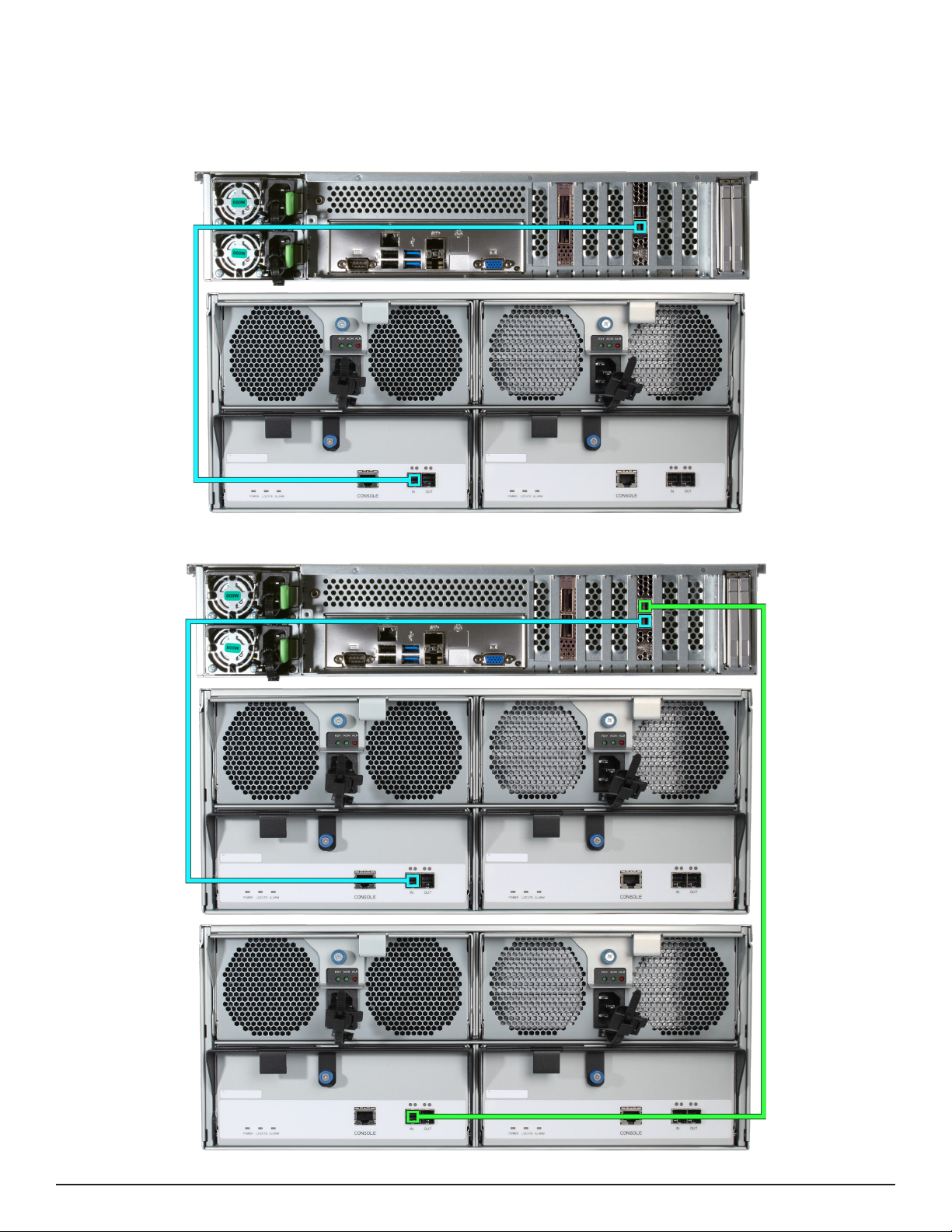
8.2.3 R50
R50 with a single ES60 Expansion Shelf
R50 with two ES60 Expansion Shelves

Page 15
8.3 M-Series
M40 with a single ES60 Expansion Shelf
M40 with two ES60 Expansion Shelves
8.3.1 M40

Page 16
8.3.2 M50 and M60
M50/M60 with three ES60 Expansion Shelves� The M50 can support up to 8 total Expansion Shelves with the use of
additional SAS cards� The M60 can support up to 12 total Expansion Shelves with the use of additional SAS cards�
M50/M60 with a single ES60 Expansion Shelf
M50 supports
up to 8
expansion
shelves
M60 supports
up to 12
expansion
shelves

Page 17
9 Install Bezel (Optional)
The included bezel is not required for operation�
Line up the screw holes on the back of the bezel with the screw holes on the ears of the ES60� Install one upper
screw from the back side of the left ES60 ear, then install a lower screw from the back of the right ES60 ear� Install
the remaining two screws following the same diagonal pattern�
10 Additional Resources
11 Contacting iXsystems
The TrueNAS Documentation Hub has complete software conguration and usage instructions� Click Guide in the
TrueNAS web interface or go directly to:
https://www�truenas�com/docs/
Additional hardware guides and articles are in the Documentation Hub’s Hardware section:
https://www�truenas�com/docs/hardware/
The TrueNAS Community forums provide opportunities to interact with other TrueNAS users and discuss their con-
gurations:
https://www�truenas�com/community/
For assistance, please contact iX Support:
Contact Method Contact Options
Web https://support�ixsystems�com
Email support@iXsystems�com
Telephone Monday-Friday, 6:00AM to 6:00PM Pacic Standard Time:
• US-only toll-free: 1-855-473-7449 option 2
• Local and international: 1-408-943-4100 option 2
Telephone Telephone After Hours (24x7 Gold Level Support only):
• US-only toll-free: 1-855-499-5131
• International: 1-408-878-3140 (International calling rates will apply)

Other manuals for ES60
3
Table of contents
Other TrueNAS Network Hardware manuals


Popular Network Hardware manuals by other brands

HP
HP 201723-B21 - HP StorageWorks Modular SAN Array 1000 Hard... Quick start instructions

Studer
Studer Xcom-MS user manual

Grandstream Networks
Grandstream Networks GVR3552 Quick installation guide

Kamstrup
Kamstrup RF Router installation guide

HP
HP c-Class overview

NETGEAR
NETGEAR MS2110 - Stora NAS Server installation guide


