TRUGGE IQ Touch & Drink BIG User manual

IQ Touch & Drink
IQ Touch & Drink BIG
From Version 5.9
Handbook for service personnel

S. 2
Table of Contents
Introduction............................................................................................................................................. 4
Important Safety Information ................................................................................................................. 6
Intended use........................................................................................................................................ 8
Environment Specifications................................................................................................................. 9
Disposal ............................................................................................................................................. 10
Product description and scope of supply.............................................................................................. 11
Installation and Comissioning ............................................................................................................... 12
Preparation Before Startup............................................................................................................... 12
Connecting the Water Line................................................................................................................ 13
Connecting the power supply ........................................................................................................... 15
Connect the Liquid Containers.......................................................................................................... 15
Setting up syrup concentrates .......................................................................................................... 16
Fill up syrup tubing............................................................................................................................ 17
Adjust concentrate suction ............................................................................................................... 17
Setting up quantities for fixed amounts............................................................................................ 18
IQ-Software ........................................................................................................................................... 20
System language selection................................................................................................................ 20
Internet connection........................................................................................................................... 21
Configure fixed IP address................................................................................................................. 21
Open setup mode.............................................................................................................................. 22
Structure of the setup window ......................................................................................................... 23
Presets, General default settings .................................................................................................. 24
Operating mode, readers, contact control and database............................................................. 27
Contact controlled......................................................................................................................... 28
MDB-Bus Interface ............................................................................................................................ 29
Database........................................................................................................................................ 30
Screen animation........................................................................................................................... 33
Weather......................................................................................................................................... 34
Tap..................................................................................................................................................... 35
General Settings ............................................................................................................................ 35
Filling quantity............................................................................................................................... 39
Valve control ................................................................................................................................. 40
Setting Concentrate in "Normal" mode ........................................................................................ 41
Settings Product details................................................................................................................. 42
Concentrate setting in "Canteen" mode....................................................................................... 43

S. 3
Statistics ............................................................................................................................................ 44
FTP-upload of statistics ................................................................................................................. 44
E-mail dispatch of the statistics..................................................................................................... 45
Copying files ...................................................................................................................................... 46
Cleaning and maintenance.................................................................................................................... 47
New liquid bag............................................................................................................................... 47
Manual cleaning ............................................................................................................................ 47
Automatic cleaning........................................................................................................................ 49
Information about cleaning........................................................................................................... 50
Daily and weekly cleaning ............................................................................................................. 50
Disinfection.................................................................................................................................... 51
Disassembling and cleaning the water jet pump .......................................................................... 52
Cleaning the cooling system.......................................................................................................... 52
Filter replacement......................................................................................................................... 53
Contact .................................................................................................................................................. 54
S. 4
SAVE THESE INSTRUCTIONS - The manufacturer suggests that these rules for
safe operation should be copied and posted in potential hazard areas. Safety
should be stressed to all operators, potential operators, and service and repair
technicians for this equipment!
Introduction
Every effort was expended to make sure that the information and instructions in this manual were
both accurate and current at the time the manual was written. However, the manufacturer reserves
the right to change, alter or otherwise improve this product at any time without prior notice.
READ THIS MANUAL THOROUGHLY
If any portion of this manual is not understood, contact the nearest Service Dealer for starting,
operating and servicing procedures.
Throughout this publication, and on tags and decals affixed to the system, DANGER, WARNING,
CAUTION and NOTE blocks are used to alert personnel to special instructions about a particular
service or operation that may be hazardous if performed incorrectly or carelessly. Observe them
carefully. Their definitions are as follows:
DANGER
After this heading, read instructions that, if not strictly complied with, will result in serious personal
injury, including death, or property damage.
WARNING
After this heading, read instructions that, if not strictly complied with, may result in personal injury
or property damage.
CAUTION
After this heading, read instructions that, if not strictly complied with, could result in damage to
equipment and/or property.
Four commonly used safety symbols accompany the DANGER, WARNING and CAUTION blocks. The
type of information each indicates is as follows:
This symbol points out important safety information that, if not followed, could endanger
personal safety and/or property of others.
This symbol points out potential explosion hazard.
This symbol points out potential fire hazard.
This symbol points out potential electrical shock

S. 5
The operator is responsible for proper and safe use of the equipment. The manufacturer strongly
recommends that the operator read this Owner’s Manual and thoroughly understand all instructions
before using this equipment. The manufacturer also strongly recommends instructing other users to
properly start and operate the unit. This prepares them if they need to operate the equipment in an
emergency.
For safety reasons, the manufacturer recommends that this equipment be installed, serviced and
repaired by a Service Dealer or other competent, qualified technician who is familiar with
applicable codes, standards and regulations. The operator also must comply with all such codes,
standards and regulations.
OPERATION AND MAINTENANCE
It is the operator’s responsibility to perform all safety checks, to make sure that all maintenance
for safe operation is performed promptly, and to have the equipment checked periodically by a
Service Dealer. Normal maintenance service and replacement of parts are the responsibility of the
owner/operator and, as such, are not considered defects in materials or workmanship within the
terms of the warranty. Individual operating habits and usage contribute to the need for
maintenance service. Proper maintenance and care of the system ensure a minimum number of
problems and keep operating expenses at a minimum. See a Service Dealer for service aids and
accessories. Operating instructions presented in this manual assume that the system has been
installed by a Service Dealer or other competent, qualified contractor. Installation of this
equipment is not a “do-it-yourself”project.
HOW TO OBTAIN SERVICE
When the system requires servicing or repairs, simply contact a Service Dealer for assistance.
Service technicians are factorytrained and are capable of handling all service needs. When
contacting a dealer about parts and service, always supply the complete Model Number, Serial
Number and Type Code (where applicable) from the DATA LABEL that is affixed to the unit.
S. 6
Important Safety Information
ELECTRICAL HAZARDS
CAUTION - Disconnect Power Before Servicing, Risk Of Electrical Shock
•The System covered by this manual provides dangerous electrical voltages and can
cause fatal electrical shock. Avoid contact with bare wires, terminals, connections, etc.
Ensure all appropriate covers, guards and barriers are in place before operating the
system. If work must be done around an operating unit, stand on an insulated, dry
surface to reduce shock hazard.
•Do not handle any kind of electrical device while stand- ing in water, while barefoot, or
while hands or feet are wet. DANGEROUS ELECTRICAL SHOCK MAY RESULT.
•If personnel must stand on metal or concrete while installing, operating, servicing,
adjusting or repairing this equipment, place insulative mats over a dry wooden
platform. Work on the equipment only while standing on such insulative mats.
•The National Electrical Code (NEC) requires the frame and external electrically
conductive parts of the system to be connected to an approved earth ground. This
grounding will help prevent dangerous electrical shock that might be caused by a
ground fault condition in the system or by static electricity. Never disconnect the
ground wire.
•Wire gauge sizes of electrical wiring, cables and cord sets must be adequate to handle
the maximum electrical current (ampac- ity) to which they will be subjected.
•Before installing or servicing this (and related) equipment, make sure that all power
voltage supplies are positively turned off at their source. Failure to do so will result in
hazardous and pos-sibly fatal electrical shock.
•In case of accident caused by electric shock, immediately shut down the source of
electrical power. If this is not possible, attempt to free the victim from the live
conductor. AVOID DIRECT CONTACT WITH THE VICTIM. Use a nonconducting
implement, such as a dry rope or board, to free the victim from the live conductor. If
the victim is unconscious, apply first aid and get immediate medical help.
•Never wear jewelry when working on this equipment. Jewelry can conduct electricity
resulting in electric shock, or may get caught in moving components causing injury.
S. 7
FIRE HAZARDS
DANGER - Risk Of Fire. Flammable Refrigerant Used. To Be Repaired Only By Trained
Service Personnel. Do Not Puncture Refrigerant Tubing.
CAUTION - Risk Of Fire. Flammable Refrigerant Used. Consult Instruction Manual/Repair
Manual/Owner's Guide Before Attempting To Install or Service This Product. All Safety
Precautions Must be Followed.
CAUTION - Risk Of Fire. Dispose Of Properly In Accordance With Federal Or Local
Regulations. Flammable Refrigerant Used.
Keep a fire extinguisher near the generator at all times. Do NOT use any carbon tetra-chloride type
extinguisher. Its fumes are toxic, and the liquid can deteriorate wiring insulation. Keep the
extinguisher properly charged and be familiar with its use. If there are any questions pertaining to
fire extinguishers, consult the local fire department.
EXPLOSION HAZARDS
DANGER - Risk Of Explosion. Flammable Refrigerant Used. To Be Repaired Only By Trained
Service Personnel. Do Not Puncture Refrigerant Tubing.
CAUTION - Risk Of Explosion. Flammable Refrigerant Used. Consult Instruction
Manual/Repair Manual/Owner's Guide Before Attempting To Install or Service This
Product. All Safety Precautions Must be Followed.
CAUTION - Risk OF Explosion. Dispose Of Properly In Accordance With Federal Or Local
Regulations. Flammable Refrigerant Used.
Properly ventilate any room or building housing to prevent build-up of explosive gas. Do not smoke
around the cooling system. Wipe up any fuel or oil spills immediately. Ensure that no combustible
materials are left in the cooling system compartment, or on or near the system, as FIRE or
EXPLOSION may result. Keep the area surrounding the system clean and free from debris. The
cooling system operates using a certain type of refrigerant. This refrigerant is potentially
FLAMMABLE and/or EXPLOSIVE and should be handled with care. Comply with all laws regulating
the storage and handling of fuels. Inspect the unit's fuel system frequently and correct any leaks
immediately. Fuel supply lines must be properly installed, purged and leak tested according to
applicable fuel-gas codes before placing this equipment into service. Natural Gas is lighter than air,
and LP gas is heavier than air; install leak detectors accordingly.

S. 8
INSTALLATION NOTES
General
•Component parts shall be replaced with like components;
•Servicing shall be done by factory authorized service personnel, so as to minimize the risk
of possible ignition due to incorrect parts or improper service; and
•A drinking water cooler having a flammable refrigerant shall not be intended for use in
lobbies or locations of egress, such as a hallway or public corridor.
•Disconnect power before performing any maintenance or service
•The unused slots of the power strip within the cabinet must not be used for other
purposes.
•Pressure Type Only: Maximum water supply line (inlet) pressure, 145 psig (1000 kPa)
•The system must have at least 4 inches clearance from walls and should be placed on flat
surfaces only.
•3rd-party software must not be installed on the computer system
Cooling System
•When working on the cooling system, the coolant can be extremely hot. Touching the
coolant or spilling the coolant on the body can cause serious injury.
•When replacing the water pump or thermostat, any coolant spilled on the floor can be
very slippery. Any coolant that spills should be wiped up immediately to reduce or
eliminate the chance of injury.
•Always wear proper clothing and eye protection when using coolant additives.
•When working on the fan, water pump, or belts, make sure the engine ignition system is
off and disconnected from the power supply
•When working on the cooling system and running the engine, always keep fingers, tools,
and clothing away from the moving fan.
Intended use
The IQ Touch & Drink is a consumer dispensing system intended to be used in commercial
enviroments. The operator is responsible providing sufficient lighting, space and a safe environment.
Conversions and changes to the system must not be made, otherwise the certification and guarantee
become invalid.
Intended use also includes observing the documentation.
For any damages resulting from usage other than agreed upon, e.g. the use of non-original parts and
equipment, any claims with respect to liability of Trugge Getränketechnik GmbH & Co.KG are
excluded.
Only concentrates released by the manufacturer must be used within the dispenser. Liquid
containers must not be refilled with alcohol or other fluids.

S. 9
Environment Specifications
Temperature Specifications
Operating: 0°C to 35°C (32°F to 95°F)
Storage: –40°C to 65°C (–40°F to 149°F)
Relative humidity Specifications (maximum)
Operating: 10 % to 90 % (non condensing)
Storage: 5 % to 95 % (non condensing)
Maximum vibration Specifications
Operating: 0.66 GRMS
Storage: 1.30 GRMS
Maximum shock Specifications
Operating: 110 G
Storage: 160 G
Altitude Specifications (maximum)
Operating: –15.2 m to 3048 m (–50 to 10,000 ft)
Storage: –15.20 m to 10,668 m (–50 ft to 35,000 ft)
Airborne contaminant level G2 or lower as dened by ANSI/ISA-S71.04-1985

S. 10
Disposal
The symbol on the product or on packaging indicates that this product may not be
treated as household waste. Instead it shall be handed over to the applicable
collection point for the recycling of electrical and electronic equipment. By ensuring
this product is disposed of correctly, you will help prevent potential negative
consequences for the environment and human health, which could otherwise be
caused by inappropriate waste handling of this product. For more detailed
information about recycling of this product, please contact your local city office, you
household waste disposal service or the shop where you purchased the product.

S. 11
Product description and scope of supply
The IQ Touch & Drink BIG by Trugge Getränketechnik GmbH & Co.KG is a computer-controlled
beverage system with touch interface. The system provides up to three different types of water: still
water, cooled still water and cooled carbonated water. You can choose freely from these types to
mix them up with up to 6 different syrup concentrates by using the integrated touch screen.
The system consists of a cabinet with the housing for the monitor and the water dispenser on top of
it. Located within the cabinet is the cooling system, a computer that holds the software for
controlling the system and a shelf for storing the liquid bags/containers.
Also included is a set of cleaning tools and supplies for proper cleaning which is described in this
manual later on.
S. 12
Installation and Comissioning
For safety reasons, the manufacturer recommends that this equipment be installed, serviced and
repaired by a Service Dealer or installation technician who is familiar with applicable codes,
standards and regulations. The operator also must comply with all such codes, standards and
regulations.
Follow these steps one after the other to avoid any problems.
Preparation Before Startup
Before commissioning check all components of the system for cracks, broken
leads, signs of overheating, sharp edges or other physical damage. If defective
components are found, replace them with like components. Use a multimeter
to check components for electrical shorts or open circuits.
Consider that the system must have at least 4 inches clearance from walls to guarantee sufficient air
circulation to avoid heat build-up. The system should be placed on flat surfaces only. If necessary
adjust the feet of the cabinet.
Make sure the water line is closed and the power supply is turned off and unplugged.
Water Connection
For proper function the water connection needs to provide at least 3 bar (44psi) and at max 10 bar
(145 psi) of water pressure. Before connecting the water line make sure it is installed properly by a
plumber service.
Never change any parts of the water line yourself!

S. 13
Connecting the Water Line
Screw the black water fitting for the system onto the water tap as shown on the picture below. Pay
special attention not to damage the sealing ring inside.
Carefully turn on the water and check for leaks in the seal area and fitting region.
If there are no leaks go on and check the pressure display on top of the filter head. If necessary, pull
up the black set screw (see picture below) until you hear a click noise in order to change the
pressure. Set it to 4 bar (58 psi) if possible but at least to 3 bar (44psi) by turning the set screw
clockwise for increasing and counter clockwise for decreasing pressure.
Once the pressure is set up correctly, push down the set screw until the click noise sounds again and
turn the black lever on top of the water filter to the right (see picture) to open the internal water
circuit.

S. 14
To avoid any water damage we highly recommend using an AquaStop valve or
something similar to prevent water from emerging.
Installed AquaStop:
S. 15
Connecting the power supply
Ensure that the power socket provides 110V at 60Hz with a working circuit breaker
and a protective conductor connection, otherwise the system must not be oprated.
Before connecting the power supply make sure the water line is connected and working. Otherwise
the cooling system might be damaged. Turn on the power strip switch inside the cabinet and connect
the power plug to the wall socket. The screen should turn on for a short period of time if done
correctly. Now the computer can be turned on by pressing the powerbutton at the top of the
computer. After the boot process has finished the IQ-Software starts automatically.
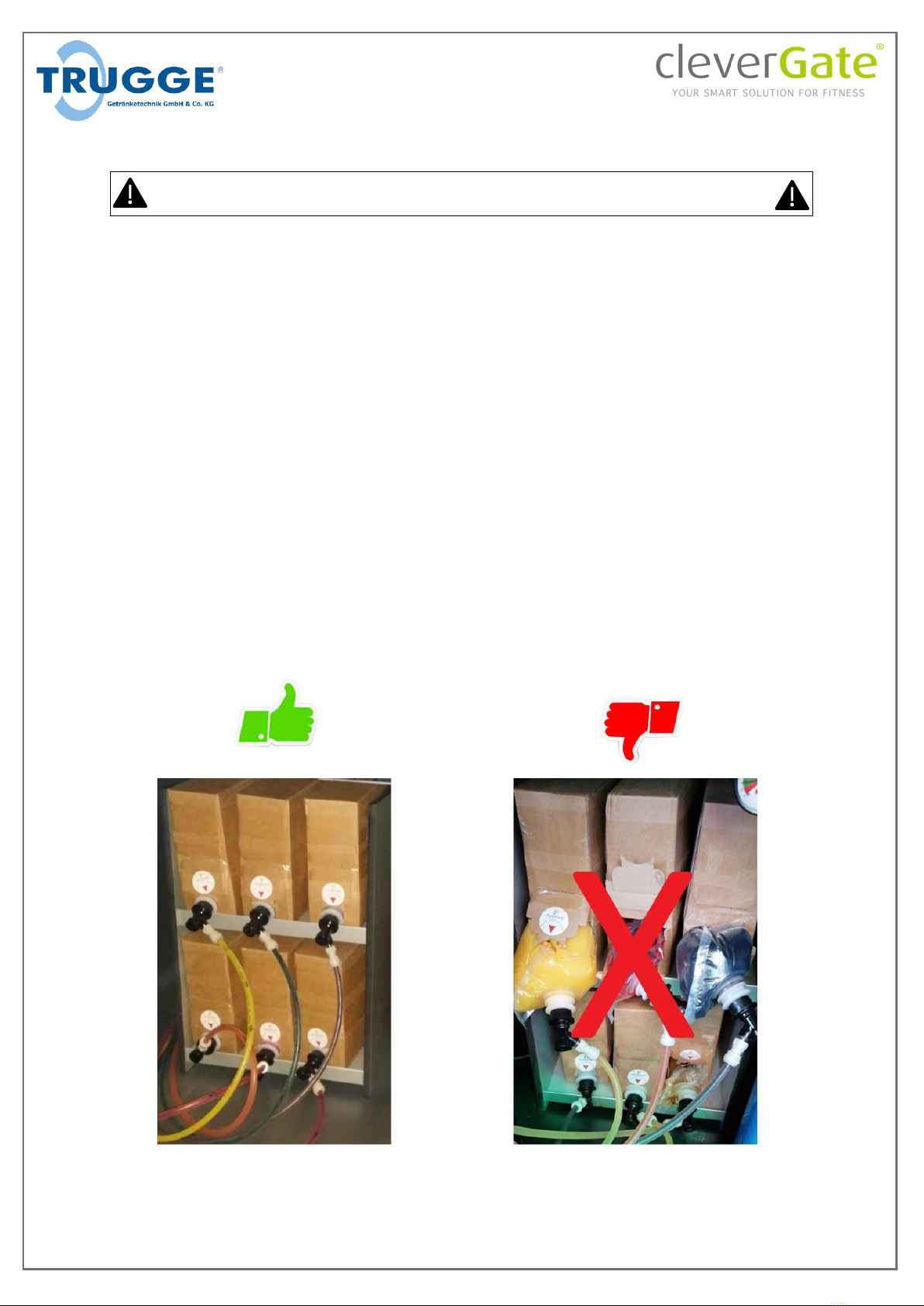
Connect the Liquid Containers
You can connect up to six several liquid bags to the unit. The bags have to be placed on the shelf
within the cabinet. The opening of each bag must be placed downwards necessarily for the system to
work properly.
Carefully open the prepunched part of the bag marked with white stickers and take them out. Then
pull out the white round connectors and place them in the whole below the sticker.
The black connection ring needs to be hung up properly into the opening of the cartonage as shown
in the picture below. Note that the plastic bag must stay inside the cartonage, otherwise the liquid
can’t flow properly.
To connect the transparent tubes to the system simply push them towards the connection of the
bags until you feel a slight resistance.
The tubing is numbered from one to six. These numbers are necessary to assign the flavors to the
touch buttons within the software later.
S. 16
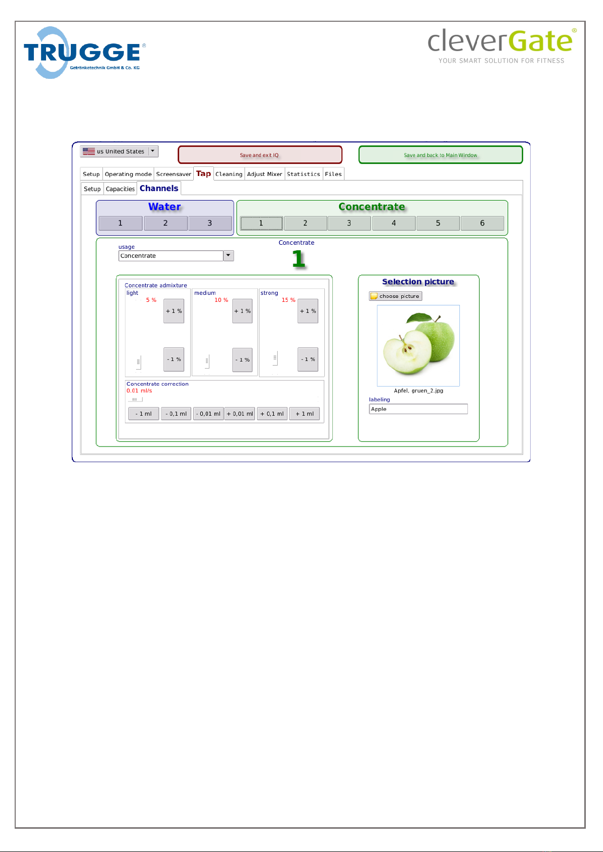
Setting up syrup concentrates
The sirup containers connected to the system need to be assigned to the software. The numbers on
the transparent tubes as described on page 15 (“Connect the Liquid Containers”) refer to the
concentrate category as seen in the picture:
To set up a certain flavor click the appropriate number below “Concentrate”. Then click “choose
picture” to select a picture from the preinstalled picture library. The labeling text will be extracted
from the file name and can also be set up manually. Each concentrate can be disabled if needed by
selecting “Off” under “usage”.
S. 17
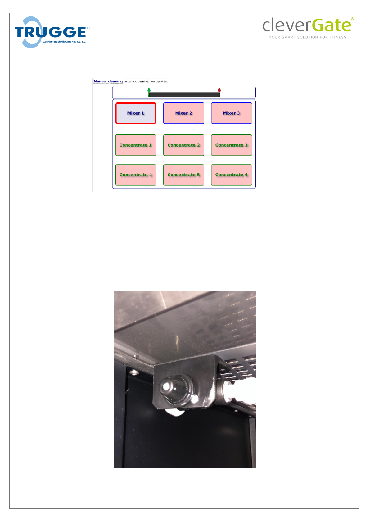
Fill up syrup tubing
The concentrate needs to aspirated into the tubing. For that open the “Cleaning” Tab and select
“manual cleaning”:
To aspirate the active concentrates, place a cup under the water outlet, press and hold each
concentrate button until the fluid changes its color.
This step is necessary whenever an empty liquid container is replaced by a new one.
Adjust concentrate suction
The suction responsible for the syrup to flow properly needs to be adjusted. This needs to be done to
prevent liquid staying within the outlet after a finished tapping process.
An adjustment screw for this purpose is located at the top left corner in the cabinet as shown on the
picture:

S. 18
Turn the screw clockwise to increase and counter clockwise to decrease suction. The adjustment
needs to be done precisely because of the screw’s high sensitivity.
To verify correct adjustment, choose a drink with conentrate. After tapping process draw pure water
and check if it is syrup-free. If the water contains syrup increase suction by an eighth of a full turn
and repeat the steps above.
Setting up quantities for fixed amounts
The amount of fluid over time depends on the water pressure the water line holds and needs to be
set up for each system individually. This is necessary for the system to work properly.
The IQ software offers up to three different fixed amounts which the customer can choose from (see
“Filling quantity”, p.39). These fixed amounts can be chosen freely. The default values are 0.3l, 0.5l
and 0.7l.
To set the amounts up a measuring cup is needed. Place it under the dispencer outlet which is
located beneath the touch monitor. Then enter setup mode (“Open setup mode”, p.22) and click
“Tap” whereupon the channel tab opens.
To select the type of water click one of the numbers below water (1: cooled, 2: still, 3: not used)
The three amounts preset under “Capacities” relate to the three buttons shown on the picture:
“Setting capacity 1”, “Setting capacity 2” and “Setting capacity 1”.
By pressing one of the capacitiy buttons a timer starts and stops when the button is released. To set
up a desired amount press and hold the appropriate button until the water in the measuring cup
reaches the chosen value. To recheck if the amount is set up correctly you can click the appropriate
“Check Amount” button and the desired capacity will be filled into the cup.

S. 19
These steps need to be repeated for each quantity in each mixer, e.g. six times for three quantities
when two mixers are used (water 1 and 2).
To save the settings hit “Save and back to Main Window” at the top right corner.
For more detailed information on settings for this category refer to “Tap”, p.35.
S. 20
IQ-Software
This chapter explains how the software on the IQ-System works and how to set it up correctly.
The operating system is Debian-based and runs the IQ-software. It must not be used for purposes
other than controlling the beverage System.
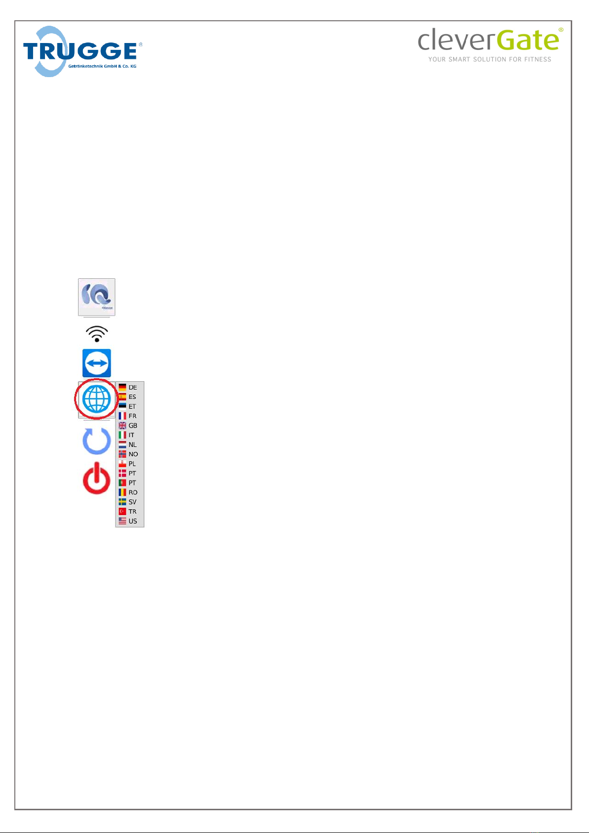
System language selection
After calling up the setup (see p.22) the program bar is displayed on the left side of the screen. By
clicking on the globe (circled in red in the figure below) a menu with all available languages opens. By
clicking on one of these languages, the system language can be changed. All necessary files will then
be generated automatically and the system will be restarted. This does not change the language of
the IQ-Software (see p.23)
Table of contents
Popular Water Dispenser manuals by other brands


Spectra Watermakers
Spectra Watermakers Z-Ion Catalina 300 Mk II installation instructions

Smith Water
Smith Water 700 Owner's manual and installation guide

Pentair
Pentair Fleck 2510 ECONOMINDER Service manual

GE
GE GXSS20H Owner's Manual & Installation Instructions

Follett
Follett 7UC100A Installation, operation and service manual

InSinkErator
InSinkErator Hot1 owner's manual