5
10/17 | 036865-047
50112 036865-003
SECTION3: INSTALLATION
WATER COOLER INSTALLATION INSTRUCTIONS, MODELS: KEPWSBF
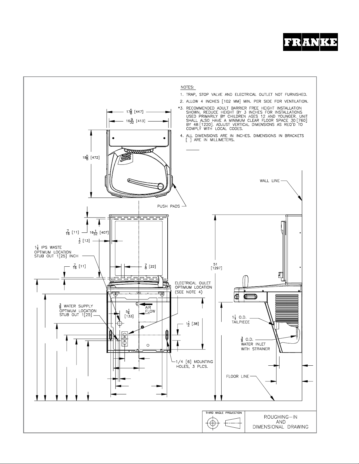
A. DRILLING HOLE IN THE TOP FOR WATER LINE CONNECTION
1. Disconnect power by UNPLUGGING unit. It might be necessary to remove the front panel to get access to the power.
2. Turn OFF water supply to the unit. It might be necessary to remove the front panel to access the water stop valve.
3. Place hole template onto cooler top so it is aligned with the left side of unit and wall. (TEMPLATE FOUND ON PAGE 17)
4. Mark hole location.
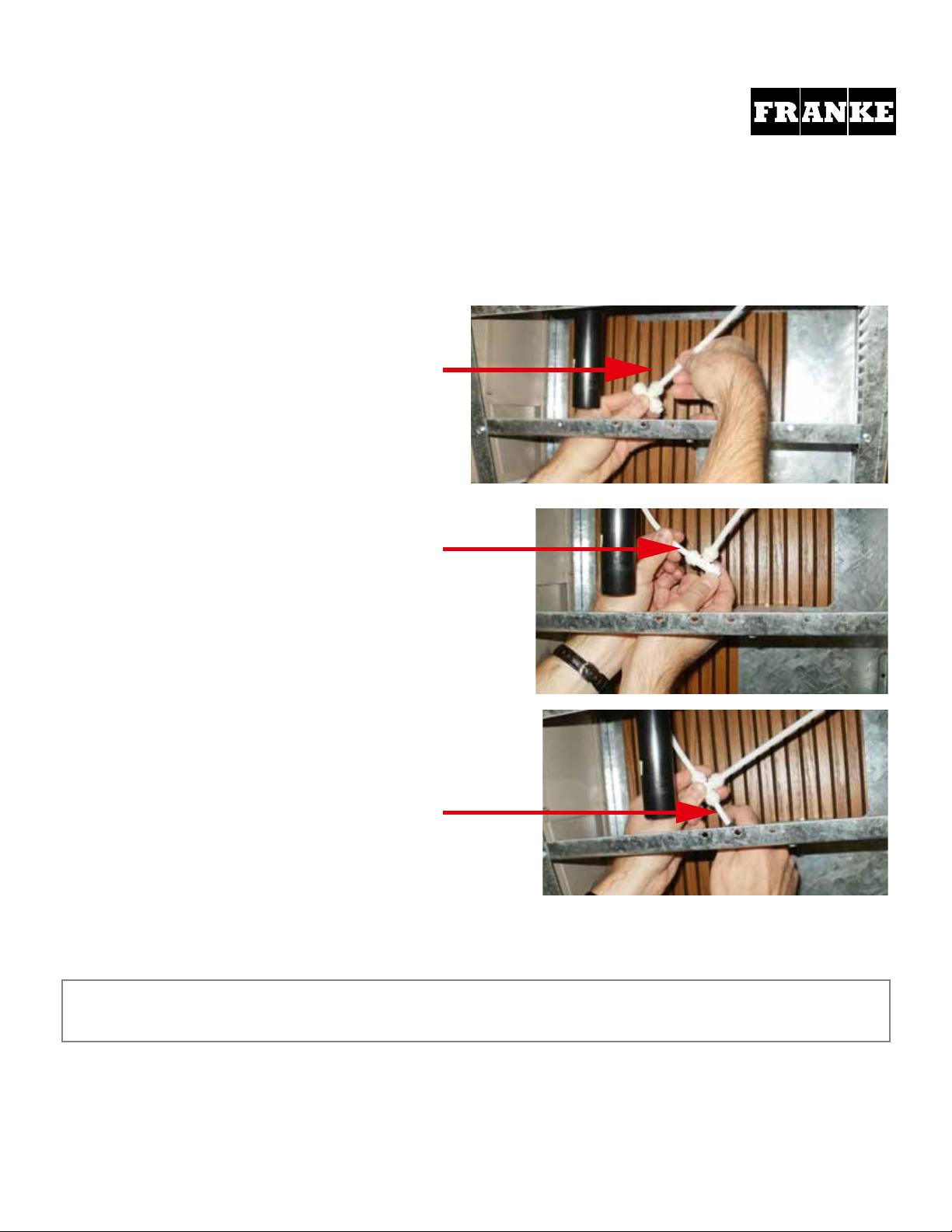
5. Remove top from unit. (Figure 1)
6. Using a 3/8 drill bit, drill a hole through top.
7. Install snap bushing into hole to protect tubing from being cut. (Figure 2)
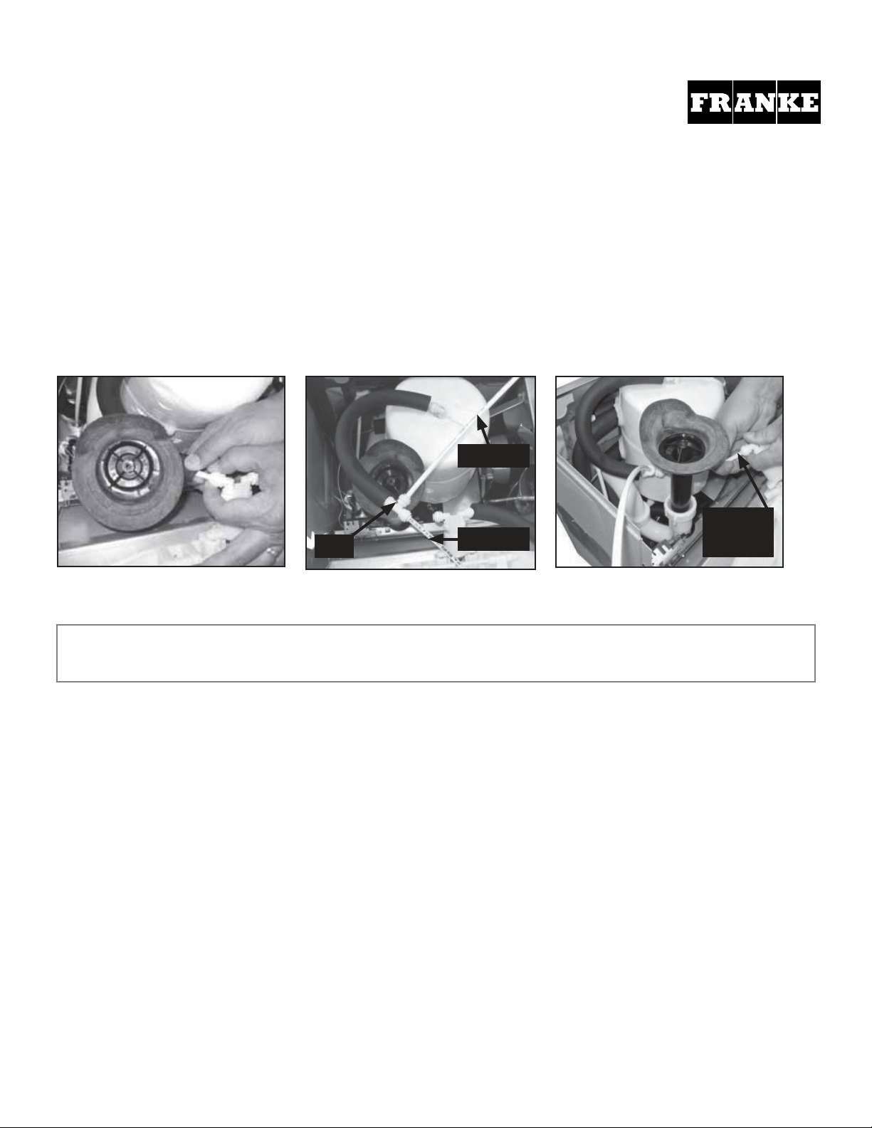
B. CONNECTING THE WATER LINE
If the cooling tank is non-pressurized, then go to the "Pressurizing the cooling tank" addendum section. Otherwise, proceed to
STEP 1 next page. Non-pressurized units are single units made since December of 2009. Refer to the schematic below to identify
the system that you have.
Mark hole location
Template
Remove top from cooler by
removing six #15 torx head
screws on sides of top.
Figure 1 Figure 2
Drill Install Bushing
PRESSURIZED
COOLING TANK
NON-PRESSURIZED
COOLING TANK
Cooling
tank
Water
valve/regulator
Supply
Water
Water
valve/regulator
Supply
Water
Cooling
tank
STEP 1:
a) Disconnect power by UNPLUGGING unit. It might be necessary to remove the front panel to get access to the power.
b) Turn OFF water supply to the unit. It might be necessary to remove the front panel to access the water stop valve.
c) Place hole template onto cooler top so it is aligned with the left side of unit and wall. SEE NEXT PAGE FOR TEMPLATE.
d) Mark hole location.
e) Remove top from unit. (Figure 1)
f) Using a step drill bit OR 7/8" punch die, make a 7/8" hole through top. You may want to drill a pilot hole to get these started.
g) Install snap bushing into hole to protect tubing from being cut. (Figure 2)
SECTION 3: INSTALLATION
A. DRILLING THE HOLE IN THE TOP FOR WATER LINE CONNECTION
PRE-DRILLED UNITS:
If your unit was purchased pre-drilled at the factory as a COMBINATION, go to Section 3, Step 5.