Trulife AEV350 User manual

AEV350, MEV350
TWO PART VALVE HOUSING,
AUTO AND MANUAL EXPULSION
Installation and User Guide
32210-001 REV A
Trulife www.trulife.com Page 1 of 4
INTRODUCTION
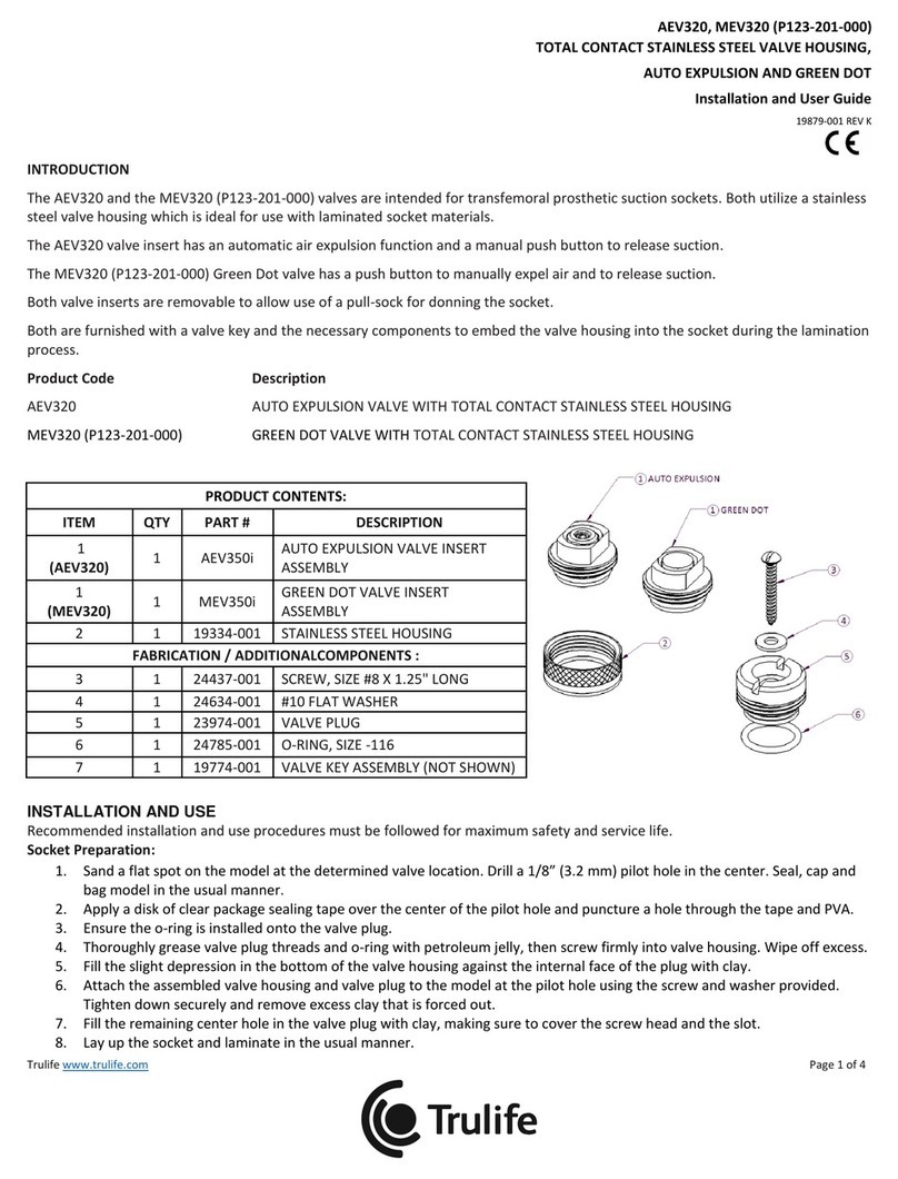
The AEV350 and the MEV350 valves are intended for transfemoral prosthetic suction sockets. Both utilize the same two-part valve
housing, which is ideal for use with flexible thermoplastic socket materials.
The AEV350 valve insert has automatic air expulsion function and manual push button to release suction.
The MEV350 valve has a push button used to manually expel air and to release suction.
Both type valve inserts are removable to allow use of a pull-sock for donning the socket.
Both are furnished with valve key and necessary components to form the socket to accept the two-part valve housing.
Product Code Description
AEV350 AUTO EXPULSION VALVE WITH TWO-PART HOUSING
MEV350 MANUAL EXPULSION VALVE WITH TWO PART HOUSING
PRODUCT CONTENTS:
ITEM
QTY
PART #
DESCRIPTION
1
(AEV350)
1
32201-001
AUTO EXPULSION VALVE INSERT
ASSEMBLY
1
(MEV350)
1
32213-001
MANUAL EXPULSION VALVE INSERT
ASSEMBLY
2
1
32207-002
SOCKET OUTER HOUSING
3
1
32212-001
O-RING, SIZE -125
4
1
32208-001
SOCKET INNER HOUSING
FABRICATION / ADDITIONALCOMPONENTS :
5
1
24437-001
SCREW, SIZE #8 X 1.25" LONG
6
1
32209-001
FORMING TOOL
7
1
19774-001
VALVE KEY ASSEMBLY (NOT SHOWN)
INSTALLATION AND USE
Recommended installation and use procedures must be followed for maximum safety and service life.
Socket Preparation:
1. Determine valve location on the positive model. Flatten the region so the forming tool is flush. Mark the center hole
location of the forming tool.
2. Drill a Ø3.2mm (Ø1/8”) pilot hole for the supplied screw.
3. Drill a vacuum channel hole 12mm (1/2”) adjacent to the pilot hole with a long drill. This hole must extend through the
model so that vacuum will draw at the forming tool site.
4. Secure the forming tool to the model with the supplied screw, and positioning it so that one of the small holes in the
forming tool is over the vacuum channel hole.
5. Vacuum form the thermoplastic socket. Manually apply the necessary external pressure around the forming tool to help
guide the softened thermoplastic to fully form around the tool.

AEV350, MEV350
TWO PART VALVE HOUSING,
AUTO AND MANUAL EXPULSION
Installation and User Guide
32210-001 REV A
Trulife www.trulife.com Page 2 of 4
6. After the socket has cooled, sand off excess plastic directly above the forming tool until the top surface of the forming tool
is exposed.
7. Remove the socket from model. Use a sanding cone to carefully open up the hole if necessary so that the inner housing fits
snug through the hole.
8. Clean the inside and outside of the formed pocket of anything that could prevent a good seal.
Final Assembly:
9. Make sure the large o-ring is seated in the groove of the flange of the inner housing and place components into the recess
formed inside the socket.
10. On the outside of the socket, screw on the aluminum outer housing, and firmly hand tighten.
Tip: To facilitate a tight fit and a good seal, wet the o-ring and the threads of the housing components with water or
isopropyl alcohol just prior to tightening.
11. Assemble the valve insert (auto expulsion or manual expulsion) by gently hand tightening clockwise until the o-ring on the
outside of the valve insert makes contact with the sealing surface inside the valve housing.
Note: To prevent cross-threading, it is sometimes necessary to initially turn the insert counter-clockwise until the
threads are aligned properly, and then tighten clockwise.
12. A valve key is provided to assist removal of the valve insertfor individuals with limited hand strength or dexterity.
Disassembly and cleaning valve inserts:
Foreign debris such as dust, baby powder, and residue from lotions used for donning the
socket can become lodged in the sealing surfaces of the valve overtime and may cause a
decrease in vacuum performance.
Instruct patients to periodically wipe clean the outer o-ring and threads of the valve insert
and the inner threads and sealing surface of the valve housing. Use water or isopropyl
alcohol.
To disassemble the valve insert for more thorough cleaning, steps 1-4 pertain to both the
auto expulsion and the manual expulsion valve inserts:
1. Remove the valve insert from the housing.
2. Firmly press down on the valve button until the valve cover
snaps off.
3. Maintain downward force of the button, while carefully
removing the inner o-ring.
This is made easier by using a small nut or other object on a
flat, sturdy work surface.
Press the assembly down onto the small object so that the
valve button lifts up from the inner seal surface.
While the valve button is lifted, use a pick to CAREFULLY
remove the o-ring from the button. DO NOT CUT OR
DAMAGE THE O-RING!
4. Remove the button and spring from the valve body. Clean
components with water and mild detergent, or isopropyl
alcohol. Ensure all sealing surfaces are free of debris or
residue.

AEV350, MEV350
TWO PART VALVE HOUSING,
AUTO AND MANUAL EXPULSION
Installation and User Guide
32210-001 REV A
Trulife www.trulife.com Page 3 of 4
Steps 5-7 pertain only to the auto expulsion valve insert:
5. Use a 3mm hex key to remove the set screw.
6. Carefully remove the small inner spring and rubber ball.
7. Clean components with water and mild detergent, or isopropyl alcohol. Ensure
that the rubber ball and inner sealing surface of the button is free of any debris or
residue.
Re-assemble valve inserts, steps 1-3 pertain to the auto expulsion version:
1. Lightly coat the rubber ball with petroleum jelly or synthetic lubricant.
2. Place the ball, followed by the small spring into the valve button.
3. Apply 1 drop of Loctite 242 or 243 (blue) to the threads of the set screw and screw
it in until it stops.
Remaining steps apply to both the Auto-expulsion and the manual expulsion valves:
4. Place the large spring over the valve button, then press and hold it through the valve body while placing the small o-ring
over the lip on the opposite side of the button to retain it in place.
5. Press the button a few times to ensure the o-ring is seated properly.
6. Position the valve cover over the lower opening of the valve and press firmly until it snaps into place.
Warning: Failure to follow the installation and use procedures set forth above may lead to failure of the components subjecting
the user to a risk of serious personal injury.

AEV350, MEV350
TWO PART VALVE HOUSING,
AUTO AND MANUAL EXPULSION
Installation and User Guide
32210-001 REV A
Trulife www.trulife.com Page 4 of 4
QUESTIONS
Contact Customer Service at;
USA
Tel: +1 800 492 1088
Fax: +1 800 245 3765
Email: info-usa@trulife.com
Canada
Tel: +1 800 267 2812
Fax: +1 613 392 4139
Email: infocanada@trulife.com
Visit Trulife online at www.trulife.com.
Trulife has appointed Medical Device Safety Service (MDSS) of Hannover, Germany to act as our EU authorized representative. They
may be contacted at:
MDSS GmbH
Schiffgraben 41
30175 Hannover
Germany
Phone (+49)-511-6262 8630
FAX (+49) -511-6262 8633
LIMITED WARRANTY
Trulife warrants that the PRODUCT will be free from defects in material and workmanship from the date of installation for the
warranty period stated on the PRODUCT warranty card.
This warranty will not apply if the PRODUCT has been damaged by misuse, abuse, neglect, improper care, failure to follow
instructions, abnormal wear and tear, or in the event that the PRODUCT has been modified/repaired by persons unauthorized by
Trulife.
If a defect in material or workmanship is found during the warranty period, Trulife will, at Trulife’s option, either repair or replace
the product. If it is not possible to repair or replace the product, Trulife will be limited to refunding the purchase price.
Trulife will not be liable under any legal theory for any direct, indirect, special, incidental or consequential damages arising from the
use of or inability to use this product.
The application guidelines for this Trulife product are for the use of and by a certified, qualified practitioner only. Patients are not to
attempt to apply or adjust the item unless expressly instructed to do so by the practitioner responsible for the prescription and/or
initial fitting of the device. All patient questions should be referred to the practitioner and not to the manufacturer. The
manufacturer warrants only that the enclosed product has been inspected for quality and can be effective for certain indications,
but final decisions and ongoing monitoring must be made by the medical professional(s) prescribing and/or fitting the device to
determine its effectiveness for an individual patient. Patient compliance is an integral part of the entire protocol and must be
adhered to in order to avoid potential problems and to maximize the effectiveness of the prescribed product.
As a condition of the sale of any Trulife product, this product is restricted to a “Single Patient Use Only” by the originally fitted
patient in order to protect the care provider and the patient against potentially adverse consequences of infectious disease
transmission, material instability in adapting to the configuration of the original user and/or decrease in effectivity. Any express or
implied warranties are voided if the product is reused or fitted to another patient. Additionally, a license of right to use under any
relevant patents pertaining to the product is terminated with the cessation of use by the original patient. As with all Trulife
products, this product must be prescribed and applied by a qualified practitioner to determine it meets the needs of the particular
patient and accomplishes the desired results.
This manual suits for next models
1
Table of contents
Other Trulife Mobility Aid manuals
