Zippie ZM-310 User manual

Owner’s Manual
Zippie®ZM-310
BC, SC
Supplier: This manual must be given to the rider of
this wheelchair.
User: Before using this wheelchair read this entire manual and save
for future reference.
SECTION ENGLISH
ZM-310
Manual de Instrucciones
Zippie®ZM-310
BC, SC
Mode d’emploi
Zippie®ZM-310
BC, SC

II. TABLE OF CONTENTS
ZI PP IE ZM-310
3127899 Rev. A
I. INTRO UCTION..........................................................................2
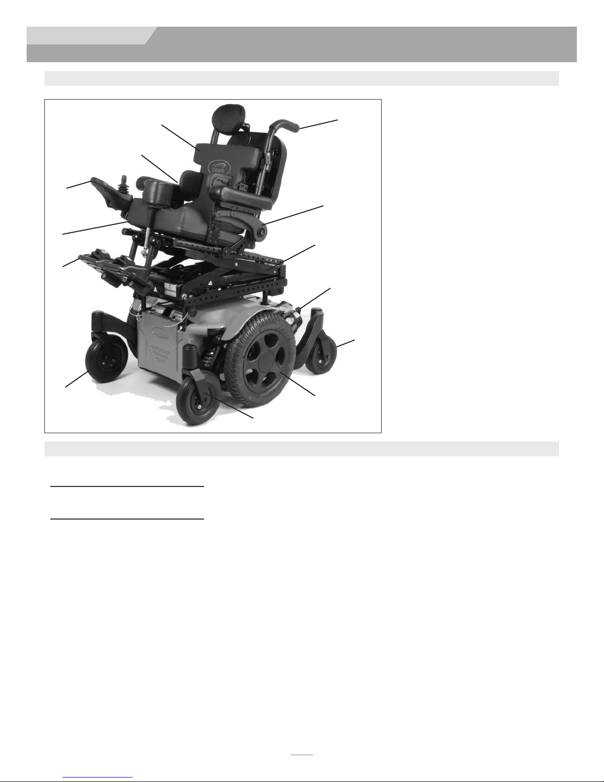
III. YOUR CHAIR AN ITS PARTS ................................................4
IV. NOTICE– REA BEFORE USE...................................................5
V. EMI (ELECTROMAGNETIC INTERFERENCE).......................5
A.What is EMI?................................................................................5
B. What effect can EMI have?.......................................................5
C.Sources of EMI.........................................................................5-6
. istance from the source.........................................................6
E. Immunity level .............................................................................6
F. Report all suspected EMI Incidents........................................6
G.EMI from chair.............................................................................6
H.Head array safety and RFI.........................................................6
VI. GENERAL WARNINGS................................................................7
A.Notice to User and Attendants ..............................................7
B. Weight Limit ................................................................................7
C.Controller settings .....................................................................7
. Safety Checklist...........................................................................7
E. Changes and adjustments .........................................................7
F. Accessories ..................................................................................7
G.When seated in a parked wheelchair ....................................8
H.Environmental Conditions........................................................8
I. Terrain ...........................................................................................8
J. Street use .....................................................................................8
K. Motor Vehicle Safety ..................................................................8
L. Center of balance .......................................................................8
M. Transfers.......................................................................................9
N.Reaching or leaning ....................................................................9
O. ressing or changing clothes...................................................9
P. Obstacles ......................................................................................9
Q. riving in reverse.......................................................................9
R. Ramps, slopes, and sidehills ......................................................9
S. To Reduce The Risk Of A Fall, Tip-Over
Or Loss Of Control ...............................................................10
T. Ramps At Home & Work .......................................................10
U.Wheel chair lifts .......................................................................10
V. Curbs and single steps ............................................................10
W. Stairs ..........................................................................................10
X.Escalators ...................................................................................10
VII. WARNINGS: COMPONENTS AN OPTIONS.................11
A.Armrests.....................................................................................11
B. Batteries......................................................................................11
C.Cushions.....................................................................................11
. Fasteners ....................................................................................11
E. Footplate, & Footrests.............................................................11
F. Motor locks ...............................................................................11
G.ON/OFF Switch........................................................................11
H.Positioning belts........................................................................11
I. Seating systems ...................................................................11-12
J. Upholstery Fabric.....................................................................12
K. Suspension..................................................................................12
L. Wiring .........................................................................................12
M.Power seating (SC & MPC)....................................................12
N.S.P.O.T. power accessory ........................................................12
O.Transit option and use ......................................................13-15
VIII. USE AN MAINTENANCE......................................................16
A.Introduction...............................................................................16
B. Cleaning ......................................................................................16
C.Storage tips ................................................................................16
. Tire pressure.............................................................................16
E. Motor brushes ..........................................................................16
F. isposing of Batteries .............................................................16
G Ordering parts ..........................................................................16
H.Maintenance chart....................................................................16
I. Folding Backrest........................................................................17
J. Swing-in/out Footrests............................................................17
K. Elevating Legrest.......................................................................17
L. Angle adjustable centermount footrest..............................17
M. ual-post fixed height standard, and ual-post height
adjustable armrests .................................................................18
N. Single post height adjustable armrests...............................18
O. Manual Recline operation .....................................................19
P. Joystick........................................................................................19
Q Omni input display ...................................................................19
R. Recline, Tilt & Lift operation..................................................20
S. Joystick Retractable Mount....................................................20
U.Joystick controller position....................................................21
V. C heck out ..................................................................................21
IX. JOYSTICK OPERATING GUI E .............................................22
A.Performance controller settings ...........................................22
B. Thermal rollback ......................................................................22
C.Joystick Stationary....................................................................22
. VR2 Joystick Assembly ............................................................22
E. RNET led joystick ....................................................................23
F. Color LC Screen....................................................................24
G.Brake lever ................................................................................25
X. BATTERIES.....................................................................................26
A.Introduction ..............................................................................26
B. Battery Charger ......................................................................26
C.Connecting Batteries ..............................................................26
. Charging Batteries....................................................................27
XI. EALER SERVICE AN A JUSTMENT................................28
A. ealer service introduction .................................................28
B. Critical maintenance tips .......................................................28
C. Cleaning ....................................................................................28
. Adjustment Notes...................................................................28
E. Shroud removal.........................................................................29
F. Battery removal........................................................................29
G.Single-post height-adjustable armrests................................30
H.Cantilever Armrests.................................................................30
I. Swing-in/out footrest adjustment .........................................31
J. Angle adjustable center mount footrest height adjust-
ment ............................................................................................31
K. Elevating legrest adjustment ..................................................31
L. Center mount hanger adjustment........................................32
M.Seat depth adjustment ...........................................................33
N.ASAP II Seating adjustments..................................................33
O.Seat removal..............................................................................33
P. Seat height adjustments ..........................................................34
Q.Seat to floor height/pre-tilt positioning ..............................34
R. Seat pan and back size adjustments.....................................34
S. Battery wiring diagram............................................................34
XII. SUNRISE LIMITE WARRANTY.............................................35

1
2
11
7
13
12
6
9
8
3
127899 Rev. A 4
ZI PP IE ZM-310
III. YOUR CHAIR AND ITS PARTS
1. Push Handles
2. Back Cushion
3. Optional Postural supports
4. VR2 controller joystick (RNET option)
5. Seat Cushion
6. Footplate (shown) (optional)
Swing-away 65° hangers
Swing-away ELR hangers
Swing-away 70° hangers
Swing-away 75° hangers (tapered)
Swing-in/out 80° hangers
Swing-in/out 90° hangers
Fixed Center mount legrest
Angle Adjustable Center Mount LR
7. Front Caster wheel 7”
8. Caster fork
9. rive Wheel
10. Rear stabilizing caster 6”
11. Brake release
12. Tilt/Lift (optional)
13. Height adjustable Cantilever armrest
Models
Zippie ZM-310 SC, BC
III. YOUR CHAIR AND ITS PARTS
ZIPPIE ZM-310
Weight (lbs)
Chair with Batteries
SC -260, BC -235
Chair without Batteries
SC -182, BC -157
rive Wheels
13" Mag: Std. airless insert
Joystick
Standard – VR2 (right-hand or
left-hand mount)
Option - VR2 w/actuator control
(SC only)
Option - RNET, LE , or Color
Batteries
(2 deep cycle batteries required to
operate chair)
Standard - Group 22
Battery Charger
Off board 8 AMP
Shroud Colors
Red, Black, Blue, Silver, Copper, Green
Apple, Yellow, Pearl Pink, Candy
Purple, Matte Black, Midnight Blue,
Pearl white, Pink, Camo, Grunge
skulls, American Flag.
Seats, Upholstery and Style
Standard- BC & SC: A.S.A.P. II Seat Frame
Sizes: 10" - 16" wide, 10” -19” deep
Footrest:
SC & BC: Standard- SA Swing away
footrests w/heel loops
Option-Foot platform
Backrest
SC & BC: Standard Canes Angle Adjust
Option- 8° Bend, Semi Recline,
Folding
Casters front
Standard- 7” solid
Casters rear
Standard- 6” solid
Armrest
SC & BC: Standard- Cantilever, height
adjustable 14" arm pad
Option- Locking, two-point arm, ual
post Arm, Single Post arm
Suspension
Standard- all wheel
All features may not be available with some
chair setups or in conjunction with another
chair feature. Please consult your supplier for
more information. Your authorized supplier
can also provide you with more information
on accessories.
5
ZIPPIE ZM-310
4
10

127899 Rev. A
5
ZI PP IE ZM-310
IV. NOTICE– READ BEFORE USE
A. CHOOSE THE RIGHT CHAIR & SAFETY
OPTIONS
Sunrise provides a choice of many power wheelchair styles, sizes and
adjustments to meet the needs of the user. However, final selection
of a wheelchair rests solely with you and your health care profes-
sional. Choosing the best chair for you depends on such things as:
1. Your size, disability, strength, balance and coordination.
2. Your intended use, and your level of activity.
3. The types of hazards you must overcome in daily use (in
areas where you are likely to use your chair).
4. The need for options for your safety and comfort (such as
positioning belts or special seat systems).
INTEN E USE: The ZM-310 is a battery operated device with
wheels that is intended for medical purposes to provide mobility
to persons restricted to a sitting position.
B. A JUST CHAIR TO YOUR ABILITY
You need to work with your doctor, nurse or therapist, and your
supplier, to fit this chair and adjust the controller settings for your
level of function and ability.
C. REVIEW THIS MANUAL OFTEN
Before using this chair you, and each person who may assist you,
should read this entire Manual and make sure to follow all instruc-
tions. Review the warnings often, until they are second nature to you.
. WARNINGS
The word “WARNING” refers to a hazard or unsafe practice that
may cause severe injury or death to you or to other persons. The
“Warnings” are in four main sections, as follows:
1. V — EMI
Here you will learn about electromagnetic interference and
how it can affect your chair.
2. VI — GENERAL WARNINGS
Here you will find a safety checklist and a summary of risks
you need to be aware of before you ride this chair.
3. VII — WARNINGS — COMPONENTS & OPTIONS
Here you will learn about your chair. Consult your supplier
and your health care professional to help you choose the
best set-up and options for your safety.
4. X — BATTERIES
Here you will learn about battery and charger safety, and
how to avoid injury.
Throughout this owner’s manual and on the wheelchair you will
see the icons listed below to identify warnings and potential haz-
ards.
WARNING! These warnings must be followed, failure to
do so may cause personal injury or may dam-
age the wheelchair.
ES : Electrostatic ischarge can damage printed
circuit boards.
V. EMI (ELECTROMAGNETIC INTERFERENCE)
WARNING
Heed all warnings to reduce the risk of unintended brake release
or chair movement:
1. Beware of the danger from hand-held transceivers. Never
turn on or use a hand-held transceiver while power to your
chair is on. Use extra care if you believe that such a device
may be in use near your chair.
2. Be aware of nearby radio or TV stations, and avoid coming
close to them.
3. If unintended movement occurs, turn your chair off as soon
as it is safe to do so.
A. WHAT IS EMI?
WARNING
1. EMI means: electromagnetic (EM) interference (I). EMI comes
from radio wave sources such as radio transmitters and
transceivers. (A “transceiver” is a device that both sends and
receives radio wave signals).
2. There are a number of sources of intense EMI in your daily
environment. Some of these are obvious and easy to avoid.
Others are not, and you may not be able to avoid them.
3. Powered wheelchairs may be susceptible to electromagnetic
interference (EMI) emitted from sources such as radio sta-
tions, TV stations, amateur radio (HAM) transmitters, two
way radios, and cellular phones.
4. EMI can also be produced by conducted sources or electro-
static discharge (ES ).
B. WHAT EFFECT CAN EMI HAVE?
WARNING
1. EMI can cause your chair, without warning, to:
• Release its brakes
• Move by itself
• Move in unintended directions
If any of these occur, it could result in severe injury to you
or others.
2. EMI can damage the control system of your chair. This could
create a safety hazard, and lead to costly repairs.
C. SOURCES OF EMI
WARNING
The sources of EMI fall into three broad types:
1. Hand-Held Transceivers:
The antenna is usually mounted directly on the unit. These include:
• Citizens band (CB) radios
• “Walkie-talkies”
• Security, fire and police radios
• Mobile phones
• Lap-top computers with phone or fax
• Other personal communication devices
• Electronic Article Surveillance Systems
NOTE– These devices can transmit signals while they are on, even if not in
use.

2. Medium-Range Mobile Transceivers:
These include two-way radios used in police cars, fire trucks,
ambulances and taxi cabs. The antenna is usually mounted on the
outside of the vehicle.
3. Long-Range Transceivers:
These include commercial radio and TV broadcast antenna towers
and amateur (HAM) radios.
NOTE– The following are not likely to cause EMI problems: Lap-
top computers (without phone or fax), Cordless phones, TV sets
or AM/FM radios, C or tape players.
. ISTANCE FROM THE SOURCE
WARNING
Electro-magnetic energy rapidly becomes more intense as you get
closer to the source. For this reason, EMI from hand-held devices
is of special concern. (See C.1 above) A person using one of these
devices can bring high levels of EM energy very close to your chair
without you knowing it.
E. IMMUNITY LEVEL
WARNING
1. The level of EM is measured in volts per meter (V/m). Every
power wheelchair can resist EMI up to a certain level. This is
called its “immunity level”.
2. The higher the immunity level, the less the risk of EMI. It is
believed that a 20 V/m immunity level will protect the power
wheelchair user from the more common sources of radio
waves.
3. The configuration tested and found to be immune to at least
20 V/m is: Zippie ZM-310 power wheelchair with a right-
hand mounted RNET remote joystick system, 18" seat width,
18" seat depth, dual post height adjustable armrests, fixed
tapered legrests with one piece solid footplate, and Gp 22
gel cell batteries.
4. All After Market input device options, classified as breath con-
trols, Proportional controls, and/or Switched controls that can
be used with this powerchair, have an unknown effect on their
immunity level to different types of EMI. They have not been
specifically tested with the ZM-310 and RNET control system:
WARNING
Individuals with physical limitations requiring the use of a specialty
control input device known not to be immune to 20V/m, or not
known, should exercise extra care around known sources of EMI.
WARNING
There is no way to know the effect on EMI if you add accessories
or modify this chair. Any change to your chair may increase the risk
of EMI. Parts not specifically tested or parts from other suppliers
have unknown EMI properties
F. REPORT ALL SUSPECTE EMI
INCI ENTS
G. EMI FROM CHAIR
WARNING
The chair itself can disturb the performance of electromagnetic
fields such as emitted by alarm systems of shops.
H. HEA ARRAY SAFETY AN RFI
WARNING
If you have a Head-array, the sensors used in the product have the
potential to operate unintentionally if moisture or any substance
that is electrically conductive is present in sufficient quantities.
Electro magnetic interference from electrical power lines and cer-
tain types of phones can cause the sensors to activate.
These sensors are capacitive in nature, and can generate an elec-
tronic field, which can be affected by liquids and/or a source of
radio frequency Interferance (RFI). Any material that is conductive
has the potential to activate the Head-array unintentionally.
Avoid use under high power lines and around cell phones.
Avoid the use of a Head Array in rain or snow and protect against
the potential of spilled liquids on the sensors.
Avoid Mobile phones and electronic devices in proximity to the
array.
Avoid any source that has the potential of (RFI).
Warn the user of this chair that the chair controls have the poten-
tial of acting erractically or making sudden stops, if (RFI) is not
avoided.
If any (RFI) causes erratic behavior, immediately cut off the power
to the wheelchair, and wait until the interference passes.
V. EMI (ELECTROMAGNETIC INTERFERENCE)
ZI PP IE ZM-310
6
127899 Rev. A

4. Propel this chair by the push handles only. They provide
secure points for you to hold the rear of the chair to pre-
vent a fall or tip-over.
5. Check to make sure push handle grips will not rotate or slip off.
B. WEIGHT LIMIT
WARNING
1. The user plus items carried should never exceed the total
weight capacity identified on your chair.
2. Never use this chair for weight training.
3. Exceeding the weight limit is likely to damage the seat, frame,
or fasteners, and may cause severe injury to you or others
from chair failure.
4. Exceeding the weight limit will void the warranty.
C. CONTROLLER SETTINGS
WARNING
Be aware that you may need to adjust the controller settings of
your chair.
1. Check and adjust the settings every six to twelve months.
2. Consult your supplier to adjust the control settings immedi-
ately if you notice any change in your ability to:
• Control the joystick
• Hold your torso erect
• Avoid running into objects.
. SAFETY CHECK-LIST
WARNING
Before each use of this chair:
1. Make sure the chair operates smoothly. Check for noise,
vibration, or a change in ease of use. (They may indicate low
tire pressure, loose fasteners, or damage to your chair).
• If you detect a problem, make sure to repair or adjust the
chair. Your supplier can help you find and correct the prob-
lem.
2. Make sure batteries are charged. Green lights on charge indi-
cator will light up when charge is full. Yellow lights indicate
battery charge level is getting low. Red lights indicate batter-
ies are in immediate need of charging.
E. CHANGES & A JUSTMENTS
WARNING
Never use non-Zippie parts to replace Zippie provided parts or
make changes to your chair unless authorized by Sunrise. ( oing so
will void the warranty and may create a safety hazard.)
F. ACCESSORIES
WARNING
Accessories designed by manufacturers other than Sunrise, not avail-
able through Sunrise order process have not been tested or
approved for use by Sunrise.
1. If you modify or adjust this chair it may increase the risk of a
fall or tip-over.
2. Modifications unauthorized by Sunrise constitutes remanufac-
turing of the wheelchair. This voids the warranty. The user
then assumes all future liability for the wheelchair.
WARNING
Heed all warnings in this section. If you fail to do so, a fall, tip-over
or loss of control may occur and cause severe injury to you or
others.
A. NOTICE TO USER AN ATTEN ANTS
WARNING
User:
1. Before using this chair, you should be trained in its safe use
by your health care professional.
2. Every wheelchair is different. Take the time to learn the feel
of this chair before you begin riding.
3. Be aware that you must develop your own methods for the
safe use of this chair that are best suited to your level of
function and ability.
4. Have someone help you practice bending, reaching and trans-
fers until you learn how to do them safely.
5. Never try a new maneuver on your own unless you are sure
it is safe.
6. Get to know the areas where you plan to use your chair.
Look for hazards and learn how to avoid them.
7. Always wear a positioning strap.
8. o not use a wheelchair if the joystick does not spring back
to the neutral position.
9. o not use your wheelchair if the joystick boot is ripped or
damaged.
10. o not try to tip this wheelchair without an attendant present.
User and Attendants:
1. When transferring the user in or out of the wheelchair
never use the footplate as a platform.
2. o not lift this wheelchair by any parts that are removable,
doing so may result in damage to the wheelchair or injury to
the user.
3. Never try to stop or slow this wheelchair with the wheel
locks (if applicable). Wheel locks are designed to prevent the
chair from moving when stopped. They are not brakes.
4. Always keep your hands and body parts clear of moving
parts to help prevent injuries.
Attendants:
WARNING
Make sure you heed all warnings and follow all instructions in each
section of this manual. Warnings that apply to the user also apply
to you.
1. o not stand or sit on any portion of this wheelchair.
2. You need to work with the user, and the user’s doctor, nurse
or therapist, to develop safe methods best suited to your
abilities and those of the user.
3. To manually push the chair you must release the motor brakes.
• o not engage or disengage motor brakes unless power to
the chair is off.
• Make sure you have full control over the chair when you
release the motor brakes. When you do so the chair will
not have brakes.
• Make sure the chair is on level ground before you release
the motor brakes.
VI. GENERAL ARNINGS
ZI PP IE ZM-310
7127899 Rev. A

G. WHEN SEATE IN A PARKE
WHEELCHAIR
WARNING
1. Always turn off all power to your chair when you are
parked, even for a moment. This will prevent:
• Accidental movement from contact with the joystick by you
or others.
• Unintended brake release or movement from EMI sources.
(See Section V)
2. Make sure that persons who help you (for example, store
clerks) are aware of the joystick and do not touch it. If they
do, your chair may move suddenly when you do not expect
it.
H. ENVIRONMENTAL CON ITIONS
WARNING
Your chair is not designed for use in a heavy rain storm, or in
snowy or icy conditions.
1. Contact with water or excessive moisture can cause an elec-
trical malfunction. The frame, motors and other chair parts
are not water-tight and may rust or corrode from the inside.
To avoid a chair failure:
• Minimize exposure of your chair to rain or very
wet conditions.
• Never take your chair into a shower, tub, pool or sauna.
• o not use your chair in fresh or salt water (such as at the
edge of a stream, lake, or ocean).
• Make sure battery cover is secure.
• Replace joystick boot if it becomes torn or cracked.
• Make sure all electrical connections are secure.
• ry the chair as soon as you can if it gets wet, or if you use
water to clean it.
2. Proceed slowly and use extra care if you must operate your
chair on a wet or slick surface.
• When in doubt, have someone help you.
• Stop if one or both main wheels lose traction. If this
occurs, you may lose control of your chair or fall.
• Never operate your chair on a slope or ramp if there is
snow, ice, water or oil film present.
3. When not in use, keep your chair in a clean, dry place.
WARNING
Extra caution should be used when employing the disc switch or
the proximity head array as control devices. These two devices are
susceptible to malfunction when wet.
I. TERRAIN
WARNING
1. This chair will perform at optimum on firm, even surfaces
such as concrete, asphalt and indoor flooring.
2. Although equipped with suspension, the performance can be
substantially reduced on uneven surfaces and rough terrain.
3. o not operate the chair on sand, loose gravel or soil. oing
so may damage wheels, bearings, axles, motors or loosen fas-
teners.
J. STREET USE
WARNING
1. This product is not intended for street use.
2. Avoid streets whenever possible.
3. Obey and follow all legal pedestrian pathways, and laws that
apply to pedestrians.
4. Be alert to the danger of motor vehicles in parking lots, or if
you must cross a road.
WARNING
K. MOTOR VEHICLE SAFETY
Identify whether your chair has been manufactured with the Transit
Option installed.
If your chair is not equipped with the Transit Option: The wheel-
chair does not meet federal standards for seating while travelling
in a motor vehicle.
1. NEVER let anyone sit in this chair while in a moving vehicle.
2. ALWAYS secure the rider with OEM motor vehicle
restraints. In an accident or sudden stop the rider may be
thrown from the chair. Wheelchair seat belts will not pre-
vent this, and further injury may result from the belts or
straps.
3. NEVER transport this chair in the front seat of a vehicle. It
may shift and interfere with the driver.
4. ALWAYS secure this chair so that it cannot roll or shift.
5. o not use any chair that has been involved in a motor vehi-
cle accident. It may have changed the structure of the chair,
and damaged, or broken components. This could lead to a
risk of injury or damage to your chair. If the wheelchair has
been involved in an accident, discontinue use and contact
your supplier for a thorough inspection.
If your chair is equipped with the Transit Option: See section VII-
O: “Transit Option and use”.
L. CENTER OF BALANCE
WARNING
The point where this chair will tip forward, back, or to the side
depends on its center of balance and stability.
The Center Of Balance Is Affected By:
1. The seat height and seat angle.
2. A change in your body position, posture or weight distribu-
tion.
3. Using this chair on a ramp or slope.
4. The use of a back pack or other options, and the amount of
added weight.
5. rive wheel positioning.
To Reduce The Risk Of A Fall Or Tip-Over:
1. Whenever a condition exists that may change the center of
balance, reduce speed, proceed cautiously.
2. When in doubt, always have someone help you.
VI. GENERAL ARNINGS
ZI PP IE ZM-310
8
127899 Rev. A

NOTE– To do this: Move your chair past the object you want to reach, then
back up alongside it. Backing up will rotate the casters forward.
3. Turn off all power to your chair. If you fail to do so, you may
touch the joystick and cause your chair to move when you
do not expect it.
O. RESSING OR CHANGING CLOTHES
WARNING
Be aware that your weight will shift if you dress or change clothes
while seated in this chair. To make the chair more stable, rotate the
front casters until they are forward.
P. OBSTACLES
WARNING
Riding over curbs or obstacles can cause tipping and serious bodily
harm. If you have any doubt that you can safely cross any curb or
obstacle, ALWAYS ASK FOR HELP. Be aware of your riding skills
and personal limitations. evelop new skills only with the help of
a companion.
1. Be aware that thresholds are very dangerous. (Even a small
change in height may stop a caster wheel and cause your
chair to tip). You may need to:
• Remove or cover threshold strips between rooms.
• Install a ramp at entry or exit doors.
2. Keep your eyes moving when you ride; scan the area well
ahead of your chair.
3. Make sure the floor areas where you use this chair are level
and free of obstacles.
Q. RIVING IN REVERSE
WARNING
Use extra care when you drive your chair in reverse. You may lose
control or fall if one of the rear wheels hits an object.
1. Operate your chair slowly and at an even speed.
2. Stop often and check to make sure your path is clear of
obstacles.
R. RAMPS, SLOPES & SI EHILLS
WARNING
Your center of balance changes when you are on a slope.
NOTE– “Slope” includes a ramp or sidehill. Your chair is less stable
when it is at an angle. Never use this chair on a slope
unless your are sure it is safe. When in doubt, have some-
one help you.
Beware Of:
1. Steep slopes. o Not use this chair on a slope steeper than
10%. (A 10% slope means: One foot in elevation for every
ten feet of slope length).
2. Wet or slippery surfaces (such as when ice, snow, water or
oil film is present). A loss of traction may cause a fall or tip-
over.
3. A change in grade on a slope (or a lip, bump or depression).
These may cause a fall or tip-over.
4. A drop-off at the bottom of a slope. (A drop-off of as small
as 3/4 inch (19 mm) can stop a front caster and cause the
chair to tip forward).
M. TRANSFERS
WARNING
It is dangerous to transfer on your own. It requires good balance
and agility. Be aware that there is a point during every transfer
when the wheelchair seat is not below you. To prevent a fall:
1. Always turn off power before you transfer to or from your
chair. If you fail to do so you may touch the joystick and
cause your chair to move when you do not expect it.
2. Make sure motor brakes are engaged. This keeps the chair
from moving when you transfer.
3. Work with your health care professional to learn safe meth-
ods for transfers.
• Learn how to position your body and how to support
yourself during a transfer.
• Have someone help you until you are sure you can do a
safe transfer on your own.
4. Move your chair as close as you can to the seat you are
transferring to. If possible, use a transfer board.
5. Rotate the front casters until they are as far forward as possi-
ble.
6. Be careful of the footrests. If you can, remove or swing them
out of the way.
• Never stand on footrests when you transfer. oing so may
damage them or cause your chair to tip.
• Make sure your feet do not “hang up” or get caught in the
space between the footrests.
7. Make sure armrests do not interfere.
8. Transfer as far back onto the seat surface as you can. This
will reduce the risk that you will miss the seat or fall.
N. REACHING OR LEANING
WARNING
Reaching or leaning affects the center of balance of your chair. If
done improperly, a fall or tip-over is likely. When in doubt, ask for
help or use a device to extend your reach.
To Reduce the Risk of injury and/or amage to the Chair:
1. Never reach or lean if you must shift your weight sideways or
rise up off the seat.
2. Never reach or lean if you must move forward in your seat
to do so. Always keep your buttocks in contact with the
backrest.
3. Never reach with both hands (you may not be able to catch
yourself to prevent a fall if you lose your balance).
4. Never try to pick up an object from the floor by reaching down
between your knees.
5. Never put pressure on the footrests while reaching.
6. Never reach or lean over the top of the seat back. This may
damage the backrest and cause you to fall.
WARNING
IF YOU MUST REACH OR LEAN, O SO AT YOUR OWN RISK.
Remember to:
1. Move your chair as close as you can to the object you wish
to reach.
2. Rotate the front casters until they are as far forward as pos-
sible. This makes the chair more stable.
VI. GENERAL ARNINGS
ZI PP IE ZM-310
9127899 Rev. A

S. TO RE UCE THE RISK OF A FALL, TIP-OVER
OR LOSS OF CONTROL
WARNING
1. Never use your chair on a slope unless you are sure you can
do so without losing traction.
2. Always go as straight up and as straight down as you can.
• o not “cut the corner” on a slope or ramp.
• o not turn or change direction on a slope.
3. Always stay in the center of the ramp. Make sure ramp is
wide enough that you are not at risk that a wheel may roll
off the side.
4. Keep your chair moving at a slow, steady speed. Keep con-
trol over the chair at all times.
• On a descent, do not let your chair accelerate beyond its
normal speed.
• If the chair picks up speed, center the joystick to slow
down or stop.
• If you stop, re-start slowly.
T. RAMPS AT HOME & WORK
WARNING
Before driving on a ramp, survey the condition of the ramp. On
slippery ramps traction may be reduced causing your wheelchair to
slide.
WARNING
NOTE– Make sure ramps meet all Building Codes for your area.
1. For your safety, have a licensed contractor build or remodel
ramp to meet all standards.
2. The proper design will vary, depending on such things as: the
length and height of the ramp; the need for an intermediate
platform; landing size; doors, and the direction of swing, and;
whether the ramp includes a turn or angle.
At A Minimum:
1. Open sides of ramp must have side rails to prevent your
chair from going over the edge.
2. Slope must not be steeper than one inch in height for every
one foot of slope length (approximately 10º).
3. Ramp surface must be even, and have a non-skid surface.
4. You may need to add a section at the top or bottom to
avoid a lip or drop-off.
5. Ramp must be sturdy. Add bracing if needed, so ramp does
not “bow” when you ride on it.
U. WHEELCHAIR LIFTS
WARNING
Wheelchair lifts are used in vans, buses, and buildings to help you
move from one level to another.
1. Always turn off all power to your chair when you are on a
lift. If you fail to do so, you may touch the joystick by acci-
dent and cause your chair to drive off the platform. (Be
aware that a “roll-stop” at the end of the platform may not
prevent this).
2. Make sure there is not a lip or drop-off at the top or bot-
tom of the platform. These may cause a fall or tip-over. When
in doubt, have someone help you.
3. Always position the user securely in the chair to help prevent
falls while on a lift.
4. Avoid moving forward if a wheel is “hung up” on the lip of
the ramp. Backup, reposition the caster for a more direct
approach. And slowly try again.
V. CURBS & SINGLE STEPS
WARNING
1. It is recommended to climb and/or descend a curb, single step,
or other obstacle that a ramp or curb cutout is always used.
2. If you must climb or descend a curb, single step, or other
obstacle that is greater than 2.5", it is recommended to have
a person assist you in doing so.
3. In no case should you try to climb a curb, single step, or
other obstacle greater than 4" high.
4. If you must climb or descend a curb or step alone do so at your
own risk using extreme care and follow the following procedure:
• Proceed slowly, at a steady speed
• Go as straight up or down as you can over the obstacle.
Never turn when trying to climb or descend and obstacle,
doing so may result in a fall or tip-over.
5. Failure to follow the above procedures may cause:
• A Fall or Tip Over
• amage to the frame, wheels, axles or other parts, or
loose fasteners.
W. STAIRS
WARNING
Never use this chair to go up or down stairs, even with an atten-
dant. oing so is likely to cause a fall or tip-over.
X. ESCALATORS
WARNING
Never take this chair on an escalator, even with an attendant.
oing so is likely to cause a fall or tip-over.
VI. GENERAL ARNINGS
ZI PP IE ZM-310
10
127899 Rev. A

F. MOTOR LOCKS
WARNING
1. o not engage or disengage motor brakes unless power to
the chair is off.
2. Be aware that the chair will not have brakes when motor
brakes are in the free-wheel position.
3. Make sure that the person pushing the chair has full control
when motor brakes are disengaged.
4. Make sure that the chair is on level ground when motor
brakes are disengaged.
G. ON/OFF SWITCH
WARNING
1. Never use the ON/OFF switch to stop the chair except in
an emergency. This will result in an abrupt stop, and may
cause you to fall.
2. To slow your chair to a stop, return the joystick to neutral.
H. POSITIONING BELTS (OPTIONAL)
WARNING
Use a positioning belt only to help support your posture. Improper
use of such belts may cause severe injury or death.
1. Make sure you are not at risk to slide down in the wheelchair
seat. If this occurs, you may suffer chest compression or suf-
focate due to pressure from the belt.
2. A pelvic wedge or a similar device can help keep you from
sliding down in the seat. Consult your health care profession-
al to find out if you need such a device.
3. The belt must be snug, but must not be so tight that it inter-
feres with breathing. You should be able to slide your open
hand, flat, between the belt and your stomach.
4. Make sure you can easily remove the belt in an emergency.
WARNING
Never use a positioning belt:
• In place of a motor vehicle seat belt. In an accident or sud-
den stop you may be thrown from the chair. A positioning
belt will not prevent this, and further injury may result from
the belt.
• As a restraint. A restraint requires a doctor’s order.
• On a user who is comatose or agitated.
I. SEATING SYSTEMS
WARNING
1. Use of a seating system not approved by Sunrise may alter
the center of balance of this chair. This may cause a fall or
tip-over.
2. Never change the seating system of your chair unless you
consult your supplier first.
3. Never raise your seating system to a height of more than
22” (measuring from the front of the seat pan to the floor)
with all actuators in their home position.
WARNING
Note: If you use parts or make changes not authorized by Sunrise
it may create a safety hazard and will void the Warranty.
A. ARMRESTS
WARNING
1. Armrests will not bear the weight of this chair.
2. Never lift this chair by its armrests. They may come loose or
break.
B. BATTERIES
WARNING
1. Only deep cycle sealed case construction batteries should be
used in this device.
2. Read all of section X. Batteries before attempting to change,
or charge batteries.
C. CUSHIONS
WARNING
1. Standard foam cushions and other body supports are not
designed for the relief of pressure.
2. If you suffer from pressure sores, or if you are at risk that
they will occur, you may need a special seat system or a
device to control your posture.
• Consult your doctor, nurse or therapist to find out if you
need such a device for your well-being.
. FASTENERS
WARNING
Many of the screws, bolts and nuts on this chair are special high-
strength fasteners. Use of improper fasteners may cause your chair
to fail.
1. Only use fasteners provided by Sunrise.
2. If fasteners become loose, tighten them immediately.
3. Over- or under-tightened fasteners may fail or cause damage
to chair parts.
E. FOOTPLATE & FOOTRESTS
WARNING
1. At the lowest point, footrests should be at least 2 1/2 inches
(65 mm) off the ground. If set too LOW, they may “hang up”
on obstacles you can expect to find in normal use. This may
cause the chair to stop suddenly and tip forward.
2. To avoid a trip or fall when you transfer:
• Make sure your feet do not “hang up” or get caught in the
space between the footrests.
• Avoid putting weight on the footrests, as the chair may tip
forward.
• Remove or swing the footrests out of the way, if possible.
3. The footrest should always be in the down position when
operating the chair.
4. Never lift this chair by the footrests. Footrests detach and
will not bear the weight of this chair. Lift this chair only by
non-detachable parts of the main frame.
VII. ARNINGS: COMPONENTS AND OPTIONS
ZI PP IE ZM-310
11 127899 Rev. A

3. Never raise your seating system to a height of more than
22" (measuring from the front of the seat pan to the floor)
with all actuators in their home position.
J. UPHOLSTERY FABRIC
WARNING
1. Replace worn or torn fabric of seat sling and seat back as
soon as you can. If you fail to do so, the seat may fail and
cause you to fall. Worn fabrics may increase the potential for
a fire hazard.
2. Sling fabric will deteriorate with age and use. Look for fray-
ing, thin spots, or stretching of fabric at rivet holes. Replace
fabric as required.
3. Be aware that washing may reduce flame retardation of the
fabric.
K. SUSPENSION
No component of the chair, was made with natural rubber latex,
Including the Suspension system.
L. WIRING
WARNING
It is possible to assign a function to an input control (buttons,
jacks) of your wheelchair . If controls have been assigned to per-
form a dual or alternate function ensure you know what each con-
trol operates. Please contact your dealer or the Zippie Technical
Service epartment if you do not receive this information. Failure
to do so may result in damage and/or injury.
M. POWER SEATING (SC &MPC)
WARNING
1. Operation
• While driving this wheelchair in the reclined, elevated, or
tilted position use caution.
• o Not attempt to operate any power seating option
while positioned on an incline.
• o Not attempt to operate any power seating option
while this wheelchair is in motion.
• o not attempt to operate the lift or tilt power seating
options around children.
• Through programming it is possible to reverse the direction
of all powered seating functions, ensure you know which
direction your seat is going to move before operating.
2. Reduced Speed riving (Creep)
This power chair is designed to automatically reduce the
maximum driving speed to a creep mode when certain
power seating limits are reached.
3. Pinch points
Pinch points may occur when operating the powered seating
options on this chair. Ensure all hands and body parts are
clear of all power seating components that may result in
pinch points before operating them.
4. Tilting Power Base with Push Handles
o not attempt to tilt power wheelchairs by pulling down on
the push handles. Power wheelchairs have heavy bases. As such,
attempting to tilt a power wheelchair to traverse obstacles can
damage components in the seating system and/or modular
actuators.
5. Remain Clear uring Power Accessory Operation
Please stay clear of any powered actuator while the compo-
nent is in motion. Sunrise power mechanisms move over
large ranges of travel. Users should be aware of their sur-
roundings while components are in motion.
6. Maximum User Weight
o not exceed the weight capacity for your specific
chair/seating system configuration. oing so could result in
premature failure or injury.
7. Latch Mode
While operating any power seating function in latched mode
use caution. In latch mode, powered seating will not stop until
a reverse command is performed or the end of travel is met.
N. S.P.O.T. (Single Power Option Tilt)
POWER ACCESSORY (SC only)
WARNING
The powered S.P.O.T. accessory for this chair has a maximum user
weight capacity of up to 165 lbs. Never exceed this capacity while
operating the powered actuator.
WARNING
The powered S.P.O.T. should not be operated for more than three
minutes of continuous use. oing so may shorten the life of the
powered S.P.O.T.
VII. ARNINGS: COMPONENTS & OPTIONS
ZI PP IE ZM-310
12
127899 Rev. A

127899 Rev. A 14
ZI PP IE ZM-310
SECUREMENT POINTS
Rear securement points(A), front securement points(B), Pelvic Belt
Securement point(C)
SECURING THE WHEELCHAIR
This wheelchair is to be used only with Wheelchair Tie-down and Occupant
Restraint Systems (WTORS) that have been installed in accordance with the
manufacturer’s instructions and SAE J2249.
NOTE–A copy of SAE J2249 Wheelchair Tie-down and Occupant Restraint
Systems (WTORS) for use in Motor Vehicles can be obtained from:
SAE International
400 Commonwealth rive.
Warrendale, PA. 15096-0001
(877) 606-7232 or (724) 776-4970
Attach WTORS to the tie-down brackets in accordance with the manufactur-
er’s instructions and SAE j2249.
SECURING THE OCCUPANT:
WHEELCHAIR-ANCHORE BELTS
WARNING
Only use a pelvic belt system that meets the requirements of ANSI-Resna WC
Vol 1 Section 19 and SAE J2249, and has been specified to work in conjunc-
tion with the Zippie ZM-310 transit system.
1. Installation
a. Install the pelvic belt ( ) onto the pelvic belt securement point
anchored to the seating frame of the Zippie ZM-310. Using a 10mm
Hex key, torque the screw to 144in-lbs securing the pelvic belt to the
mounting anchor (E).
b. Repeat step 1 for the opposite side.
VEHICLE-ANCHORE BELTS
WARNING
This wheelchair has an overall rating of “A” with regard to accommodating
the use and fit of vehicle-anchored belts. This rating is scored as follows: A =
Excellent, B = Good, C = Fair, = poor.
The test for Lateral Stability isplacement for Point (P) is shown in the figure
at right. The average test result for point (P) is:
• Zippie ZM-310 - 0.547inches (13.9mm)
NOTE–Figure 5 shows the rear view of the wheelchair and human surrogate
secured on test platform and tilted to 45°.
SEATING SYSTEM
WARNING
This wheelchair has been tested for seating in a motor vehicle with the facto-
ry installed seating system only. Ensure that the factory installed seating sys-
tem is secured to the wheelchair frame before operation. Refer to the seat-
ing system owner’s manual for further information.
4
3
5
4
5
3
VII. ARNINGS: COMPONENTS & OPTIONS
3
4
5
E
B
A
C

127899 Rev. A
15
ZI PP IE ZM-310
POSITIONING BELTS
WARNING
The angle of the pelvic belt should be within the preferred zone of 45 to 75
degrees to the horizontal or within the optional zone of 30 to 45 degrees to
the horizontal. Steeper side-view pelvic belt angles are especially important if
the pelvic belt is intended to be used for postural support in addition to
occupant restraint in a frontal crash. Steeper angles will reduce the tendency
for a vertical gap to develop between the user and the belt due to compliance
of seat cushions and belt movement, thereby reducing the tendency for the
user to slip under the belt and for the belt to ride up on the soft abdomen
during normal use. Steeper belt angles also reduce the tendency for upper-
torso belts to pull the pelvic belt onto the abdomen during a frontal impact
loading.
1. Proper Installation
a. The pelvic belt should be worn low across the front of the pelvis.
b. Position the upper torso belts over the shoulders.
c. The belt(s) should not be held away from the body by the wheelchair
components or parts, including
but not limited to the armrests or wheels.
d. Ensure the belt(s) are not twisted.
e. Adjust belts as firmly as possible being mindful of user comfort
f. Place the upper-torso belt across the middle of the shoulder and the
center of the chest, and connect to the pelvic belt near the hip of the
power chair occupant.
GENERAL USE WARNINGS
WARNING
If the total weight of the power chair exceeds 275lbs(125Kg), it is recom-
mended that two additional ANSI/RESNA WC/Vol.4, Section 18/ISO 10542
compliant rear securement straps be used to anchor the power chair during
motor vehicle transport. For power chairs that exceed the weight threshold
mentioned above, It is further recommended that the vehicle used for trans-
port have a gross vehicle weight greater than 8800lbs(4000Kg) if the option
exists.
WARNING
The buckle of the belt restraint system should not be located near any item
that may come in contact with the buckle release button in the event of a
vehicle accident or collision.
WARNING
If a recline angle is required during transport, the Power chair seat/back
should be positioned at an angle of no more than 30° to the vertical or the
occupant is at risk of injury from sliding under the restraint in the event of an
accident or collision while in the motor vehicle.
WARNING
Visually inspect all WTORS equipment at least once per month, and have
worn or broken components replaced immediately.
WARNING
Interior components that can’t be removed from the clear zones should be
padded with material that complies with FMVSS201.
678
VII. ARNINGS: COMPONENTS & OPTIONS
6
7
WARNING
Although postural supports and belts may be used in a
moving vehicle in addition to the occupant belt restraint
system, they should not be relied upon to replace occu-
pant restraints that have been designed and tested for
the purpose of securing an occupant during a motor
vehicle collision or accident. Any postural supports that
can be used during transit, must be positioned so that
they do not interfere with the clear path for proper
transit securement belt restraint.
If an Upper torso belt is in use, the anchor point(A)
should be above and behind the occupant to ensure
the occupant is properly restrained during transport.
A
8

127899 Rev. A 16
ZI PP IE ZM-310
VIII. USE AND MAINTENANCE
E. MOTOR BRUSHES
Check the motor brushes every four (4) months for wear. The
brushes should be clean and shiny. Replace worn or blackened
brushes
F. ISPOSING OF BATTERIES
WARNING
1. All batteries once they have reached the end of their useful
life are deemed to be hazardous waste.
2. For further information on handling and recycling contact
your local recycling authority.
3. Always dispose of product through a recognized agent.
G. OR ERING PARTS
When you order parts, provide the following:
1. Model of chair
2. Serial number of chair
3. Left hand or right hand control
4. Part number, description and quantity of parts you need.
5. State reason for replacement.
H. MAINTENANCE CHART
You should check the items on this chart at the indicated intervals.
If any of the items are loose, worn, bent or distorted, immediately
have them checked and/or repaired by your authorized Sunrise sup-
plier. Frequent maintenance and servicing will improve performance,
extend wheelchair life, and help prevent injuries.
WARNING
The owner and/or Caregiver for the use of this product, is responsible for
making sure that it has been setup and adjusted by a trained service profes-
sional under the advice of a healthcare advisor. The chair may require
periodic maintenance or certain in-use adjustments that may be performed
by the owner or caregiver.
A. INTRO UCTION
WARNING
1. Your chair needs regular maintenance for peak performance
and to avoid injury from chair failure, damage or premature
wear.
2. Inspect and maintain this chair per the “Maintenance Chart”.
3. If you detect a problem, make sure to service or repair the
chair before use.
4. At least once a year, have a complete safety check and service
of your chair performed by a supplier.
B. CLEANING
1. Paint Finish:
• Clean the paint finish with mild soapy water monthly.
• Protect the paint with a coat of non-abrasive auto wax every
three months.
2. Motors:
• Clean around motor area weekly with a slightly damp (not
wet) cloth.
• Wipe off or blow away any fluff, dust, or dirt on or around
the motors.
NOTE– You do not need to grease or oil the chair.
3. Upholstery:
• Hand-wash only as needed. Machine washing may damage
fabric.
• rip-dry only. Heat from a dryer may damage fabric.
NOTE– Washing the fabric may decrease fire retardant properties.
C. STORAGE TIPS
1. Store your chair in a clean, dry area. If you fail to do so, parts
may rust or corrode.
2. Before using your chair, make sure it is in proper working
order. Inspect and service all items on the “Maintenance
Chart”.
3. If you store this chair for more than three months, have it
inspected by a supplier before use.
c. Use petroleum jelly to re-grease the terminals after connect-
ing cable to battery. (Completely cover the terminal nut and
bolt, cable clip and any exposed cable with jelly).
. TIRE PRESSURE
WARNING
Residual air pressure in tires can cause severe injury. Make sure
you release all air in tire before attempting to service or have your
tires repaired.
1. rive Wheels:
a. It is important to keep the correct air pressure in your tires
at all times. You can find the correct pressure in Psi, or
Kilopascals on the sidewall of your tire.
b. Remove the air stem cap.
c. Inflate the tire to the proper pressure level (listed on the tire
sidewall)
aily
Weekly
Monthly
Quarterly
Annually
Charge Batteries R
Check tires for proper inflation level R
Check plugs and connectors for
proper connections R
Check all moving parts for wear R
Inspect all nuts, bolts and fasteners
for looseness or wear R
Inspect upholstery for wear R
Service by authorized supplier R
CHECK...

127899 Rev. A
17
ZI PP IE ZM-310
HEADER
VIII. USE & MAINTENANCE
9
10
11
E
CB
A
I. FOL ING BACKREST
Zippie ZM-310 wheelchairs are shipped with backrest in folded position. (optional)
1. Upright Positioning
a. Lift backrest to upright position so that latch handles (A) lock into place.
b. Backrest is ready for use.
2. Folding Backrest
a. Lift and turn backrest latch handles (A) inward or outward.
b. Fold backrest forward.
WARNING
Backrest latches must be locked into place before operating wheelchair.
J. SWING-IN/OUT FOOTRESTS
Swing-in-Swing-out Hangers and Footrests are available in (80° & 90º)
1. Installation
a. From the side, place the pivot ( ) into the top of the frame tube which guides the hanger into
the correct alignment with the locking plate (C) on front frame tube.
b. Rotate the hanger to the front until it locks into place on locking plate.
2. Removal
a. To remove footrest, release latch (B) by pulling lever upward or pushing lever downward.
b. Rotate footrest inward or outward and lift it out of the front frame tube.
K. ELEVATING LEGREST (Optional)
1. Installation
To install or remove Elevating Legrest (ELR) see instructions for Swing-away Footrest instal-
lation.
2. Adjustment
a. To raise legrest, lift to desired position. Legrest will automatically lock in place.
b. To lower legrest, while seated in chair, first lift slightly then press release lever (E)
down and lower legrest to desired position.
L. ANGLE A JUSTABLE CENTER MOUNT FOOTREST
1. Quick Independent angle adjustment
a. epress the button(F) and angle adjust the footplates as an assembly or indepen-
dantly of each other.
2. Adjustment
a. To raise legrest, lift to desired position. Legrest will automatically lock in place.
b. To lower legrest, while seated in chair, first lift slightly then press the button (F) and
lower legrest to desired position.
10
11
9
12
12
F

127899 Rev. A 18
ZI PP IE ZM-310
HEADER
M. UAL-POST FIXE HEIGHT STAN AR
UAL-POST HEIGHT-A JUSTABLE ARMRESTS (Optional),
The dual-post flip-back armrest can be used as either a flip-back armrest or a removable
armrest.
1. Installing Armrest
a. Insert front and rear posts into armrest receivers.
b. Engage levers (A and B) to secure armrest.
2. Set-up for Flip-back Operation
a. isengage lever (A) so front post is able to come free.
b. Armrest now has the ability to be flipped back without removal.
3. Set-up for Removal
a. isengage levers (A and B) so front and rear posts are able to come free.
b. Armrest can now be easily removed for transferring.
4. Height-Adjustment (option)
a. Release the upper securing lever (C).
b. Set at desired height
c. Return securing lever to locked position.
d. Move armrest up or down to allow armrest to snap into place
N. SINGLE POST HEIGHT-A JUSTABLE ARMRESTS (Optional)
1. Installation
a. Slide the outer armpost into the receiver mounted to the wheel chair frame.
b. The armrest will automatically lock into place.
2. Height Adjustment
a. Rotate release lever to stop.
b. Slide armrest pad up or down to desired height.
c. Return lever to locked position.
d. Push arm pad until upper armpost locks firmly into place.
3. Removing Armrest
a. Rotate release lever and remove the armrest.
4. Replacing Armrest
a. Slide armrest back into receiver.
b. Return release lever to locked position against armpost.
13
14
VIII. USE & MAINTENANCE
9
2
6
7
1
4
3
5
8
Height-Adjustable Armrest Key
1. Inner Arm Post
2. Receiver
3. Release Lever, Locked Position
4. Armrest Pad
5. Transfer Bar
6. Side Panel
7. Tension Adjustment Set Screw
8. Outer Arm Post
9. Receiver Adjustment Bolts
14
13
B
C
A

127899 Rev. A
19
ZI PP IE ZM-310
HEADER
VIII. USE & MAINTENANCE
LC
screen
Profile +/-
Navigation
Mode
On/Off
Omni isplay 18
15
Power
module
Joystick
communication
cable
17
LE Color
Joysticks 16
A
B
O. MANUAL RECLINE OPERATION
The ASAP II seating system has two manual recline options. The first is using a 16mm
socket wrench at point (A) and the second can be done by using the manual recline knob
(B) on the side of the chair. To recline the chair, rotate this knob clockwise and turn the
knob counter-clockwise to return the back to a more upright position.
P. JOYSTICK
Controls:
Two types of joysticks are available: LE and Color isplay.
The joystick assembly has 3 components: The Joystick, The Power Module, and the
communications cable.
Q. OMNI INPUT ISPLAY
The Omni is a universal specialty controls interface that accepts signals from many differ-
ent types of SI s and translates them into commands compatible with the PG rives
Technology RNET control system. Examples of these might include: Breath Control,
Proportional Head Control, Mini-Joystick, and many others.
15
1716
18

127899 Rev. A 20
ZI PP IE ZM-310
R. RECLINE, TILT & LIFT OPERATION
The recline, tilt and lift features on your chair can all be operated using the joystick on
your chair. Follow the instructions below to operate:
1. Make sure your controller is on.
2. From the rive Mode, press the Mode button (A) to enter Power Seating Mode.
3. Move the joystick left or right selecting the power option (recline, tilt, lift, legrests)
you wish to control.
4. Move the joystick forward or backward to adjust the selected power option to the
desired position.
5. Press the Mode button to return to normal operation or continue moving the joy-
stick left or right to adjust the next power option. Multiple Mode button presses
will be necessary if other modules, or Output, are active.
Mating Connectors
To connect the communication cables: Holding the connector housing, firmly push the
connector into its mate until you can no longer see the yellow plastic. The connectors are
secured using a friction system.
To disconnect the communication cables: Holding the connector housing firmly, pull the
connectors apart.
NOTE– o not hold or pull on the cable. Always grip the connector when connecting and discon-
necting.
When the control system is first switched on after a connection, or system component
change, the timer will be displayed while the system checks itself. Then the re-start icon
will be displayed. Switch the control system off and on again to operate,
S. JOYSTICK RETRACTABLE MOUNT (Optional)
The joystick or Enhanced isplay is mounted with a mechanism which allows the control
to be locked in a forward or retracted position using magnets.
Adjustment
a. To retract the joystick, push outward on the inside of joystick.
b. Push the joystick away from front of armrest until it locks into retracted position.
c. To return to forward position, push the joystick forward until it locks into place.
19
20
21
VIII. USE AND MAINTENANCE
21
20
19
A

127899 Rev. A
21
ZI PP IE ZM-310
T. JOYSTICK CONTROLLER POSITION
You can move the controller in or out in relation to the armrest. You can also move the
controller to either side of your chair to accomodate left or right-hand use.
WARNING
Be careful of pinching your controller cords. When the controller is moved, the harness
and cord can be at risk of pinching from the Seat frame, and/or the Power base frame. Be
sure to route and secure the cord with a zip tie to avoid cord pinching,. Cord pinching
could eventually disable your power chair if left unchecked.
Before Moving the controller from one side to the other read these important tips.
a. Turn off the power to the controller.
b. Unplug the controller connectors from the power base.
c. Remove any wire ties securing the controller harness to the armrest.
d. Flip up the armrest so that it is perpendicular to the floor.
e. Loosen the hardware on the controller bracket and slide the controller out.
f. Re-tighten the hardware, so it won’t be lost accidentally.
g. Loosen the hardware on the other armrest.
h Slide the controller arm into the other armrest, and tighten the hardware.
i. Route and secure the controller harness to the back of the power base and plug in
the controller cord. Make sure to avoid any areas where the cord may be pinched.
Adjustment and/or switch sides.
a. To adjust the joystick, forward or back, loosen the clamp(A), move the joystick, and
then hand-tighten the clamp handle.
b. To move the joystick to the opposite side of the chair, remove the hardware(B) and
move the clamp and joystick receiver to the other armrest.
c. Tighten all hardware to avoid any movement of the joystick while travelling.
U. CHECK-OUT
Once the wheelchair is assembled and adjusted, it should roll smoothly and easily. All acces-
sories should the checked to make sure they are also performing smoothly. After the wheel-
chair has been set-up, be sure that the chair performs to ytour specified operational settings.
If the chair does not perform the way you expect it to, (according to specifications), turn
your wheelchair OFF immediately and contact your authorized supplier to re-program oper-
ational settings using the RNET operating guide.
If you have any problems, follow this Procedure:
a. Review the Set-up, Adjustment, and use section and the Operating Guide to make sure
the chair was properly prepared.
b. If your problem persists, contact your authorized supplier. If you still have a problem
after contacting your authorized supplier, contact Sunrise Medical Customer service.
See the introduction page for details of how to contact the people who can help you.
22 22
A
B
VIII. USE AND MAINTENANCE

127899 Rev. A 22
ZI PP IE ZM-310
127899 Rev. A
VR2 Joystick
23
A
C
B
E
F
A. PERFORMANCE CONTROL SETTINGS
NOTE– BEFORE attempting to check and/or adjust settings on your joy-
stick, be sure to see your dealer or clinician and have them
make adjustments if needed.
1. It is vital to match control settings to your level of function
and ability.
2. Consult your health care professional and your supplier to
select the best control settings for you.
3. Check and adjust the settings every six to twelve months.
WARNING
Adjust the control settings immediately if you notice any change in
your ability to:
• Control the joystick.
• Avoid running into objects.
• Control settings can be adjusted by your dealer
B. THERMAL ROLLBACK
Your chair has a Thermal Roll Back Circuit. This protects the con-
troller from damage due to overheating. In extreme conditions
(such as repetitive hill climbing), the circuit will decrease the power
to your motors. This allows the chair to operate at a reduced
speed, without overheating the components. When the controller
cools, the chair will return to a normal speed.
C. JOYSTICK STATIONARY
Your chair has an available programming feature called “Joystick
Stationary” which can be set by your dealer. This feature senses
when the joystick is displaced from neutral, yet left in a steady posi-
tion for a predetermined period of time. The controller will auto-
matically turn off if the set time has been reached. This feature is
designed to protect the user, batteries and electronics if the joystick
is inadvertently displaced. There are two parameters that can be
adjusted:
1. Joystick Stationary Time:
This is the time the joystick has to remain within the station-
ary range before the unit will come to a stop. It can be pro-
grammed from 0 to 60 minutes in steps of one minute.
Select 0 to disable the function. efault setting is 0
( isabled).
2. Joystick Stationary Range:
This determines the size of a region around the present joy-
stick position. If the joystick remains within this region for
the stationary time the controller will stop. The range can be
programmed from 1 to 50, in steps of 1. efault setting is 1.
WARNING
Before turning on or adjusting these parameters, carefully read and
understand the implications for use of these features, Joystick
Stationary Time and Joystick Stationary Range. When the “Joystick
Stationary Time” is reached within the “Joystick Stationary Range”,
the drive motors on the chair will shut off. As an example, this will
happen while driving in a straight line for extended periods of time
with no joystick movement. Once the drive motors turn off, the
user will need to turn the chair off and back on to drive.
. VR2 JOYSTICK ASSEMBLY
The standard VR2 joystick controls the chair’s performance. It con-
sists of the following parts:
1. Speed Control or rive Mode Selection Buttons (A, B and C)
a. To decrease the speed level depress button(A). Or, when 1-
5 rive modes are programmed, depress button A to acti-
vate lower drive mode(s).
b. To increase speed level, depress button (B). Or, when 1- 5
rive modes are programmed, depress button B to activate
higher drive mode(s).
c. Speed level active is indicated on display (C) by a series of
five lights. One light indicates slowest level currently active,
while five lights indicates highest level currently active.
d. rive Mode is indicated by a single light. The first light indi-
cates rive Mode 1; the second light indicates Mode 2, and
so on.
2. Battery Charge Indicator ( )
isplays the charge available in the battery and alerts the user
when the charge level is low.
• Steady: Indicates that all is well.
• Flashing Slowly: The control system is functioning correctly, but
you should charge the battery as soon as possible.
• Stepping Up: The wheelchair batteries are being charged. You will
not be able to drive the wheelchair until the charger is discon-
nected and you have switched the control system off and on
again.
• If the battery gauge shows red, yellow and green, the batteries
are charged (bars 1-10).
• If the battery gauge shows just red and yellow, then you should
charge the batteries as soon as you can (bars 1-7).
• If the battery gauge shows just red, then you should charge the
batteries immediately (bars 1-3).
3. On/Off Button (E)
Turning the chair on or off is accomplished by depressing button E.
4. Horn (F)
23
IX. JOYSTICK OPERATING GUIDE
Other manuals for ZM-310
1
Table of contents
Popular Mobility Aid manuals by other brands

panthera
panthera Bambino 3 Assembly instructions

Russka
Russka 11447 000 manual

Rebotec
Rebotec QUADRO User instructions

identités
identités NEO STRONG instruction manual

Mart Cart
Mart Cart 280-3563 Owner's manual and technical documentation

Harbor Freight Tools
Harbor Freight Tools 68055 Owner's manual & safety instructions