Truma TEB-3 User manual

Gebrauchsanweisung Seite 2
Im Fahrzeug mitzuführen!
Operating instructions Page 7
To be kept in the vehicle!
Mode d’emploi Page 12
À garder dans le véhicule !
Istruzioni per l’uso Pagina 17
Da tenere nel veicolo!
Gebruiksaanwijzing Pagina 22
In het voertuig meenemen!
Brugsanvisning Side 27
Skal medbringes i køretøjet!
Bruksanvisning Sida 32
Skall medföras i fordonet!
Page39
TEB-3 / TN-3

2
Sicherheitshinweise
Wartungs- und Reparaturarbeiten dürfen nur
von einem Fachmann ausgeführt werden!
Vor Wartungs- bzw. Reparaturarbeiten das
Gebläse allpolig vom Netz bzw. der Batterie
trennen!
Dieses Gerät kann von Kindern ab 8 Jahren und
darüber sowie von Personen mit verringerten
physischen, sensorischen oder mentalen Fähig-
keiten oder Mangel an Erfahrung und Wissen
benutzt werden, wenn sie beaufsichtigt oder
bezüglich des sicheren Gebrauchs des Gerätes
unterwiesen wurden und die daraus resultie-
renden Gefahren verstehen.
Kinder dürfen nicht mit dem Gerät spielen.
Verwendungszweck
Gebläse zur Montage an einer Heizung Truma S 3004 oder
S 5004.
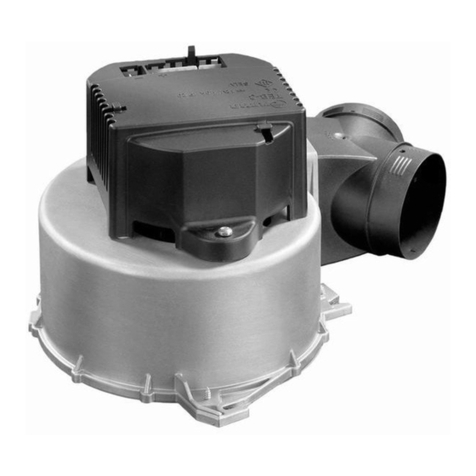
Gebläse TEB-3 / TN-3
Verwendete Symbole
Symbol weist auf mögliche Gefahren hin.
ESD-Vorschriften beachten! Elektrostatische Aufladung
kann zum Zerstören der Elektronik führen. Vor Berüh-
rung der Elektronik Potentialausgleich herstellen.
Hinweis mit Informationen und Tipps.
Inhaltsverzeichnis
Verwendete Symbole ............................................................ 2
Sicherheitshinweise .......................................................... 2
Verwendungszweck .......................................................... 2
Gebrauchsanweisung
Inbetriebnahme .................................................................. 3
Sicherungswechsel (nur TEB-3 – 12 V) ................................. 4
TN-3 – 230 V ....................................................................... 4
Entsorgung .......................................................................... 4
Technische Daten ............................................................... 5
Truma Hersteller-Garantieerklärung ............................... 6

3
Inbetriebnahme
Vor Inbetriebnahme unbedingt Gebrauchsanweisung
beachten! Der Fahrzeughalter ist dafür verantwortlich, dass
die Bedienung des Gerätes ordnungsgemäß erfolgen kann.
TEB-3 – 12 V
Externes Bedienteil Trumavent
man
auto
12 V
1
2
3
4
5
e
d
c
a
b
Integriertes Bedienteil
5
4
3
2
1
A
O
M
c
e
f
d
a
b
a = Drehknopf für die Gebläseleistung (1 – 5)
b = Drehschalter für die Betriebsarten
c = Automatikbetrieb (Heizen)
Die Elektronik regelt die erforderliche Gebläseleistung und
begrenzt die Drehzahl auf den eingestellten Wert.
d = Aus
Gebrauchsanweisung e = Manuelle Einstellung der Gebläseleistung
Gewünschte Drehzahl am Drehknopf (a) einstellen.
f = Booster-Stufe (nur bei integriertem Bedienteil)
Gebläseleistung auf höchstem Wert – maximaler
Luftvolumenstrom.
Bei Verwendung von Netz- bzw. Stromversorgungsgerä-
ten beachten, dass diese eine geregelte Ausgangsspan-
nung zwischen 11 V und 15 V liefern und die Wechselspan-
nungswelligkeit < 1,2 Vss beträgt.

4
Sicherungswechsel (nur TEB-3 – 12 V)
ESD-Vorschriften beachten!
Die Gerätesicherung (F1) befindet sich auf der elektronischen
Steuereinheit im Gerät.
– Gebläse spannungsfrei schalten (Batterie abklemmen,
gegebenenfalls Netzstecker ziehen).
– Stecker der Spannungsversorgung und des Bedienteils
abziehen.
– 2 Schrauben (1) am Gehäuse lösen – Gehäuse abnehmen.
– Platine am Rand anfassen und aus dem Gehäuse ziehen.
– Defekte Sicherung nur durch eine baugleiche Sicherung
ersetzen (siehe „Technische Daten“).
– Platine in das Gehäuse einsetzen.
– Gehäuse nach dem Sicherungswechsel mit 2 Schrauben (1)
am Gebläse befestigen.
– Stecker des Bedienteils und der Spannungsversorgung auf-
stecken (auf richtige Polung achten – sonst ist das Bedien-
teil ohne Funktion und das Gebläse läuft in umgekehrter
Richtung).
– Batterie wieder anklemmen, gegebenenfalls Netzverbindung
wieder herstellen.
F1
1
TN-3 – 230 V
Externes Bedienteil
1
2
3
4
5
230 V ~
Trumavent
d
c
a
b
a = Drehknopf für die Gebläseleistung (1 – 5)
b = Drehschalter für die Betriebsarten
c = Aus
d = Ein, manuelle Einstellung der Gebläseleistung
Gewünschte Drehzahl am Drehknopf (a) einstellen.
Entsorgung
Das Gerät ist gemäß den administrativen Bestimmungen
des jeweiligen Verwendungslandes zu entsorgen. Nationale
Vorschriften und Gesetze (in Deutschland ist dies z. B. die
Altfahrzeug-Verordnung) müssen beachtet werden.

5
Technische Daten
TEB-3 – 12 V
Spannungsversorgung SELV (Safety Extra Low Voltage)
12 V
Sicherung (im Gerät)
M – mittelträge – 2,5 A; 5 x 20 mm; nach EN 60127-2-3
z. B. ESKA 521021 oder Littelfuse 233 02.5P
Stromaufnahme
0,2 bis 1,2 A
Luftfördermenge
bis 149 m3/h (frei ausblasend)
Maße
211 x 279 x 145 mm
Gewicht
1,1 kg
Technische Änderungen vorbehalten!
TN-3 – 230 V
Spannungsversorgung
230 V ~, 50 Hz
Stromaufnahme
0,5 A
Luftfördermenge
bis 170 m3/h (frei ausblasend)
Maße
211 x 279 x 158 mm
Gewicht
1,7 kg
Technische Änderungen vorbehalten!

6
Truma Hersteller-Garantieerklärung
1. Garantiefall
Der Hersteller gewährt Garantie für Mängel des Gerätes, die
auf Material- oder Fertigungsfehler zurückzuführen sind. Da-
neben bestehen die gesetzlichen Gewährleistungsansprüche
gegen den Verkäufer fort.
Der Garantieanspruch besteht nicht
– für Verschleißteile und bei natürlicher Abnutzung,
– infolge Verwendung von anderen als Truma Originalteilen in
den Geräten,
– bei Gasdruck-Regelanlagen infolge Schäden durch Fremd-
stoffe (z. B. Öle, Weichmacher) im Gas,
– infolge Nichteinhaltung der Truma Einbau- und
Gebrauchsanweisungen,
– infolge unsachgemäßer Behandlung,
– infolge unsachgemäßer Transportverpackung.
2. Umfang der Garantie
Die Garantie gilt für Mängel im Sinne von Ziffer 1, die in-
nerhalb von 24 Monaten seit Abschluss des Kaufvertrages
zwischen dem Verkäufer und dem Endverbraucher eintreten.
Der Hersteller wird solche Mängel durch Nacherfüllung be-
seitigen, das heißt nach seiner Wahl durch Nachbesserung
oder Ersatzlieferung. Leistet der Hersteller Garantie, beginnt
die Garantiefrist hinsichtlich der reparierten oder ausgetausch-
ten Teile nicht von neuem, sondern die alte Frist läuft weiter.
Weitergehende Ansprüche, insbesondere Schadensersatz-
ansprüche des Käufers oder Dritter sind ausgeschlossen. Die
Vorschriften des Produkthaftungsgesetzes bleiben unberührt.
Die Kosten der Inanspruchnahme des Truma Werkskunden-
dienstes zur Beseitigung eines unter die Garantie fallenden
Mangels – insbesondere Transport-, Wege-, Arbeits- und
Materialkosten – trägt der Hersteller, soweit der Kundendienst
innerhalb von Deutschland eingesetzt wird. Kundendienstein-
sätze in anderen Ländern sind nicht von der Garantie gedeckt.
Zusätzliche Kosten aufgrund erschwerter Aus- und Einbau-
bedingungen des Gerätes (z. B. Demontage von Möbel- oder
Karosserieteilen) können nicht als Garantieleistung anerkannt
werden.
3. Geltendmachung des Garantiefalles
Die Anschrift des Herstellers lautet:
Truma Gerätetechnik GmbH & Co. KG
Wernher-von-Braun-Straße 12
85640 Putzbrunn, Deutschland
Bei Störungen wenden Sie sich bitte an das Truma Service-
zentrum oder an einen unserer autorisierten Servicepartner
(siehe www.truma.com). Bezeichnen Sie bitte Ihre Beanstan-
dungen im Detail und geben Sie die Seriennummer des Gerä-
tes sowie das Kaufdatum an.
Damit der Hersteller prüfen kann, ob ein Garantiefall vorliegt,
ist durch den Endverbraucher das Gerät auf seine Gefahr zum
Hersteller / Servicepartner zu bringen oder ihm zu übersen-
den. Bei Schäden am Wärmetauscher ist der verwendete Gas-
druckregler mit einzusenden.
Bei Klimasystemen:
Zur Vermeidung von Transportschäden darf das Gerät nur
nach Rücksprache mit dem Truma Servicezentrum Deutsch-
land oder dem jeweiligen autorisierten Servicepartner ver-
sandt werden. Andernfalls trägt das Risiko für eventuell ent-
stehende Transportschäden der Versender.
Bei Einsendung ins Werk bitte per Frachtgut versenden. Im
Garantiefall übernimmt das Werk die Transportkosten bzw.
Kosten der Einsendung und Rücksendung. Liegt kein Garan-
tiefall vor, gibt der Hersteller dem Kunden Bescheid und nennt
die vom Hersteller nicht zu übernehmenden Reparaturkosten;
in diesem Fall gehen auch die Versandkosten zu Lasten des
Kunden.

7
Safety instructions
Maintenance and repair work may only be car-
ried out by an expert.
Disconnect the fan from the power supply
or the battery (all poles) before carrying out
maintenance or repair work.
This appliance may be used by children from
8 years old and by persons with disabilities or
with a lack of experience only if they are super-
vised or have been instructed in the safe use
of the appliance and understand the resulting
risks.
Children must not be allowed to play with the
appliance.
Intended use
Fan for installation on a Truma S3004 or S5004 heater.
Fan TEB-3 / TN-3
Symbols used
Symbol indicates possible hazards.
Observe the ESD regulations! Electrostatic charging can
cause destruction of the electronics. Ensure that poten-
tial compensation is present before touching the electronics.
Note containing information and tips.
Table of contents
Symbols used ........................................................................ 7
Safety instructions ............................................................ 7
Intended use ....................................................................... 7
Operating instructions
Start-up ................................................................................ 8
Fuse change (TEB-3 – 12 V only) .......................................... 9
TN-3 – 230 V ....................................................................... 9
Disposal ............................................................................... 9
Technical data ................................................................... 10
Truma Manufacturer’s Warranty ................................... 11

8
Start-up
Always observe the operating instructions prior to
starting. The vehicle owner is responsible for correct
operation of the appliance.
TEB-3 – 12 V
External control panel Trumavent
man
auto
12 V
1
2
3
4
5
e
d
c
a
b
Integrated control panel
5
4
3
2
1
A
O
M
c
e
f
d
a
b
a = Control knob for fan power (1 – 5)
b = Rotary switch for operating modes
c = Automatic mode (Heating)
The electronics control the fan power required and limit
the speed to the set value.
d = Off
Operating instructions e = Manual fan power setting
Set desired speed with control knob (a).
f = Booster level (only with integrated control panel)
Fan power to highest value – maximum air flow volume.
When power packs or power supply units are being
used, note that the output voltage is between 11 V and
15 V and the alternating current ripple is < 1.2 Vpp.

9
Fuse change (TEB-3 – 12 V only)
Observe the ESD regulations.
The appliance fuse (F1) is on the electronic control unit in the
appliance.
– Switch fan so that it is voltage-free (disconnect battery, dis-
connect mains plug if necessary).
– Remove connectors from power supply and control panel.
– Remove 2 screws (1) from the housing – take off housing.
– Hold the edges of the PCB and pull it out of the housing.
– Always replace defective fuses with identical fuses (see
“Technical data”).
– Insert PCB into the housing.
– Secure housing to fan with 2 screws (1) after changing the
fuse.
– Attach connectors of control panel and power supply (ob-
serve correct polarity, otherwise the control panel will not
function and the fan will run in the wrong direction).
– Reconnect battery, re-establish mains connection if necessary.
F1
1
TN-3 – 230 V
External control panel
1
2
3
4
5
230 V ~
Trumavent
d
c
a
b
a = Control knob for fan power (1 – 5)
b = Rotary switch for operating modes
c = Off
d = On, manual fan power setting
Set required speed with control knob (a).
Disposal
The appliance must be disposed of in accordance with the ad-
ministrative regulations of the respective country in which it is
used. National regulations and laws (in Germany, for example,
the End-of-life Vehicle Regulation) must be observed.

10
Technical data
TEB-3 – 12 V
SELV power supply (Safety Extra Low Voltage)
12 V
Fuse (in the appliance)
M – medium time-lag – 2.5 A; 5 x 20 mm;
complies with EN60127-2-3
e.g. ESKA 521021 or Littelfuse 233 02.5P
Power consumption
0.2 to 1.2 A
Air delivery volume
up to 149 m3/h (free blowing)
Dimensions
211 x 279 x 145 mm
Weight
1.1 kg
Subject to technical changes.
TN-3 – 230 V
Power supply
230 V ~, 50 Hz
Power consumption
0.5 A
Air delivery volume
up to 170 m3/h (free blowing)
Dimensions
211 x 279 x 158 mm
Weight
1.7 kg
Subject to technical changes.

11
Truma Manufacturer’s Warranty
1. Warranty claims
The Manufacturer hereby warrants for all defects of the unit
caused by material or production faults. In addition, the seller
continues to be subject to any statutory warranty claims.
No warranty claim shall be applicable under the following
circumstances:
– Consumable parts which are subject to wear and tear
– Use of parts other than original Truma components in any
of the units
– In gas pressure regulation systems: damage caused by
foreign substances in the gas (e.g. oils, plasticisers)
– Failure to observe Truma’s installation or operating instructions
– Improper handling
– Improper transport packing
2. Scope of warranty
The warranty covers all defects under clause 1 that occur
within 24 months upon concluding the purchase agreement
between the seller and the end customer. The Manufacturer
undertakes to remedy such defects through subsequent fulfil-
ment, i.e. at its discretion either by repairing or replacing the
defective item. If the Manufacturer remedies a defect under
its warranty commitment, the term of the Warranty shall not
recommence anew with regard to the repaired or replaced
parts; rather, the original warranty period shall continue to be
applicable. No further-reaching claims shall be permitted, es-
pecially damage claims presented by purchasers or third par-
ties. This provision shall not affect the validity of the German
Product Liability Act (Produkthaftungsgesetz).
The Manufacturer shall bear the cost of employing the Truma
Customer Service for the removal of warranty defects – in
particular, transportation, travelling, job and material costs –
provided that the Customer Service conducts its work within
Germany. This Warranty does not cover Customer Service
work outside Germany.
Additional costs arising from complicated removal or installa-
tion jobs on the unit (e.g. dismantling of furnishings or parts
of the vehicle body) are not covered by the Warranty.
3. Making a claim under the warranty
The Manufacturer‘s address is:
Truma Gerätetechnik GmbH & Co. KG
Wernher-von-Braun-Straße 12
85640 Putzbrunn, Germany
Should problems occur, please contact the Truma Service Centre
or one of our authorised service partners (see www.truma.com).
Please describe your claim in detail and state the serial number
of the unit and the date of purchase.
To help the Manufacturer determine whether your claim is
covered by the Warranty, the end user must take or send the
unit to the Manufacturer or service partner at their own risk.
In the event of damage to the heat exchanger, the gas pres-
sure regulator, too, must be returned along with the unit.
Air conditioning systems:
To avoid transport damage, the unit must be sent either to
the Truma Service Centre in Germany or to the relevant au-
thorised service partner; this must only be done upon prior
arrangement. Otherwise the sender shall bear the risk for any
transport damage that may occur.
If a unit is sent to the manufacturing facility, make sure it
is shipped as a freight item. If the claim is covered by the
Warranty, transport / shipping and the cost of return shall
beborne by the manufacturing facility. If the claim is not
covered by the Warranty, the Manufacturer shall notify the
customer to this effect, specifying the cost of repairs not
borne by the Manufacturer; shipping costs, too, shall be
borne by the customer in such a case.

12
Informations concernant la sécurité
Seul un spécialiste est autorisé à effectuer les
travaux de maintenance et de réparation.
Déconnectez le ventilateur sur tous les pôles du
secteur ou de la batterie avant de procéder à
des travaux de maintenance ou de réparation.
Cet appareil peut être utilisé par des enfants
à partir de 8 ans ainsi que des personnes aux
capacités physiques, sensorielles ou mentales
restreintes ou bien manquant d’expérience et
de connaissances à condition d’être sous sur‑
veillance ou d’avoir été instruits sur l’utilisation
sûre de l’appareil et de comprendre les risques
en résultant.
Les enfants ne doivent pas jouer avec l’appareil.
Utilisation
Ventilateur pour montage sur un chauffage Truma S 3004 ou
S 5004.
Ventilateur TEB-3 / TN-3
Symboles utilisés
Ce symbole indique des risques possibles.
Respecter les prescriptions ESD. Une charge électro‑
statique peut provoquer la destruction de l’électronique.
Avant de toucher l’électronique, établir la compensation de
potentiel.
Remarque avec informations et conseils.
Table des matières
Symboles utilisés ................................................................ 12
Informations concernant la sécurité ............................ 12
Utilisation .......................................................................... 12
Mode d’emploi
Mise en service ................................................................ 13
Remplacement de fusible
(seulement TEB‑3 – 12 V) .................................................... 14
TN-3 – 230 V ..................................................................... 14
Mise au rebut .................................................................... 15
Caractéristiques techniques .......................................... 15
Déclaration de garantie du fabricant Truma ............... 16

13
Mise en service
Avant la mise en service, observer impérativement
le mode d’emploi ! Il incombe au détenteur du véhicule
de veiller à ce que l’appareil puisse être utilisé de façon
conforme.
TEB-3 – 12 V
Pièce de commande externe Trumavent
man
auto
12 V
1
2
3
4
5
e
d
c
a
b
Pièce de commande intégrée
5
4
3
2
1
A
O
M
c
e
f
d
a
b
a = bouton de réglage de la puissance du ventilateur (1 – 5)
b = commutateur rotatif de sélection du mode de
fonctionnement
c = mode automatique (chauffage)
L’électronique règle la puissance de ventilation requise et
limite la vitesse à la valeur réglée.
d = arrêt
Mode d’emploi e = réglage manuel de la puissance du ventilateur
Réglage de la vitesse souhaitée sur le bouton de réglage (a).
f = niveau d’amplification seulement pour pièce de com‑
mande intégrée)
Puissance du ventilateur sur la valeur maximale – flux
volumétrique d’air maximal.
En cas d’utilisation d’adaptateurs secteurs ou d’appareils
d’alimentation en courant, veiller à ce qu’ils fournissent
une tension de sortie régulée entre 11 V et 15 V et que l’ondu‑
lation de tension alternative soit < 1,2 Vcc.

14
Remplacement de fusible
(seulement TEB‑3 – 12 V)
Respecter les prescriptions ESD.
Le fusible (F1) se trouve sur l’unité de commande électronique
de l’appareil.
– Mettre le ventilateur hors circuit (déconnecter la batterie, le
cas échéant retirer la fiche de la prise de courant).
– Retirer la fiche de l’alimentation en tension et de la pièce de
commande.
– Desserrer 2 vis (1) du boîtier et retirer le boîtier.
– Saisir la platine sur le bord et la retirer du boîtier.
– Remplacer le fusible défectueux uniquement par un fusible
similaire (voir «Caractéristiques techniques»).
– Placer la platine dans le boîtier.
– Fixer le boîtier au ventilateur avec 2 vis (1) après le rempla‑
cement du fusible.
– Emboîter la fiche de la pièce de commande et de l’alimen‑
tation en tension. (Veiller à la bonne polarité, sinon la pièce
de commande ne fonctionnera pas et le ventilateur tournera
dans le sens inverse).
– Reconnecter la batterie et, le cas échéant, rétablir la liaison
au secteur.
F1
1
TN-3 – 230 V
Pièce de commande externe
1
2
3
4
5
230 V ~
Trumavent
d
c
a
b
a = bouton de réglage de la puissance du ventilateur (1 – 5)
b = Commutateur rotatif de sélection du mode de
fonctionnement
c = arrêt
d = marche, réglage manuel de la puissance du ventilateur
Réglage de la vitesse souhaitée sur le bouton de réglage (a).

15
Mise au rebut
L’appareil doit être éliminé conformément aux règles admi‑
nistratives du pays d’utilisation. Les prescriptions et lois
nationales doivent être respectées (en Allemagne, il s’agit
par exemple du décret sur les véhicules hors d’usage).
Caractéristiques techniques
TEB‑3 – 12 V
Alimentation en tension SELV (Safety Extra Low Voltage)
12 V
Fusible (dans l’appareil)
M – à action semi‑retardée – 2,5 A; 5 x 20 mm;
selon EN60127‑2‑3 par exemple ESKA 521021 ou
Littelfuse 233 02.5P
Consommation de courant
de 0,2 à 1,2 A
Débit d’air
jusqu’à 149 m3/h (soufflage libre)
Dimensions
211 x 279 x 145 mm
Poids
1,1 kg
Sous réserve de modifications techniques!
TN‑3 – 230 V
Alimentation en tension
230 V ~, 50 Hz
Consommation de courant
0,5 A
Débit d’air
jusqu’à 170 m3/h (soufflage libre)
Dimensions
211 x 279 x 158 mm
Poids
1,7 kg
Sous réserve de modifications techniques!

16
Déclaration de garantie du fabricant Truma
1. Cas de garantie
Le fabricant concède une garantie pour les vices de l’appareil im‑
putables à des défauts de matériaux ou de fabrication. En outre,
le recours légal en garantie à l’encontre du vendeur reste valable.
La garantie ne s’applique pas
– pour les pièces d’usure et en cas d’usure naturelle,
– suite à l’utilisation de pièces autres que des pièces origi‑
nales Truma dans les appareils,
– en cas de dommages causés par des corps étrangers
(p.ex. huiles et plastifiants) dans le gaz des installations de
détente de gaz,
– en cas de non‑respect des instructions de montage et du
mode d’emploi de Truma,
– en cas d’utilisation non conforme,
– en cas d’emballage de transport inapproprié.
2. Étendue de la garantie
La garantie couvre les vices au sens du point 1, survenant dans
les 24 mois suivant la conclusion du contrat d’achat entre le
vendeur et le consommateur final. Le fabricant remédiera à ces
défauts par une exécution ultérieure, c’est‑à‑dire au choix par
une réparation ou par la livraison d’un appareil de rechange.
Si le fabricant fournit une garantie, le délai de garantie concer‑
nant les pièces réparées ou remplacées ne recommence pas
du début, l’ancien délai continue à courir. Toutes autres préten‑
tions, en particulier toutes prétentions à dommages‑intérêts
de l’acheteur ou de tiers, sont exclues. Les dispositions de la
législation allemande sur la responsabilité du fait des produits
défectueux (Produkthaftungsgesetz) restent inchangées.
Les coûts de mise à contribution du service après‑vente usine
Truma pour remédier à un défaut couvert par la garantie,
en particulier coûts de transport, de déplacement, de main
d’œuvre et de matériaux, sont à la charge du fabricant, dès
lors que le SAV intervient sur le territoire de la République
fédérale d’Allemagne. La garantie ne couvre pas les interven‑
tions de service après‑vente dans les autres pays.
Les coûts supplémentaires dus à des difficultés de démontage et
de remontage de l’appareil (par ex. désassemblage d’éléments de
meubles ou de carrosserie) ne sont pas reconnus comme garantie.
3. Invocation du cas de garantie
Adresse du fabricant :
Truma Gerätetechnik GmbH & Co. KG
Wernher‑von‑Braun‑Straße 12
85640 Putzbrunn, Allemagne
Veuillez vous adresser au centre de SAV Truma ou à un de
nos partenaires de SAV agréés en cas de dysfonctionnements
(voirwww.truma.com). Veuillez spécifier vos réclamations
avec autant de précision que possible et indiquer le numéro
de série de l’appareil et la date d’achat.
Pour que le fabricant puisse vérifier le bien‑fondé du recours
en garantie, le consommateur final doit apporter ou expé‑
dier l’appareil à ses risques au fabricant / partenaire de SAV.
Envoyer également le détendeur utilisé en cas de dommages
de l‘échangeur thermique.
Pour les systèmes de climatisation :
Afin de prévenir tous dommages dus au transport, l‘appareil
ne doit être expédié qu’après concertation avec le centre de
SAV Truma Allemagne ou le partenaire de SAV agréé res‑
pectif. Dans le cas contraire, l’expéditeur devra supporter le
risque de dommages éventuels dus au transport.
Veuillez prévoir une expédition en régime ordinaire pour le
renvoi à l’usine. En cas d’application de la garantie, l’usine
prend en charge les coûts de transport ou les coûts d’envoi et
de retour. Si le dommage n’est pas couvert par la garantie, le
fabricant en avise le client et lui communique le montant du
coût de la réparation qu’il devra supporter ; dans ce cas, les
coûts d’expédition sont également à la charge du client.

17
Avvertenze di sicurezza
Far eseguire riparazioni e interventi di ma-
nutenzione esclusivamente ad un tecnico
qualificato!
Prima di eseguire riparazioni o interventi di
manutenzione, scollegare il ventilatore dalla
rete e dalla batteria su tutti i poli!
Questo apparecchio può essere utilizzato da
bambini a partire da 8 anni d’età e persone
con capacità fisiche, sensoriali o psichiche
limitate o senza esperienza né conoscenze
dietro sorveglianza oppure se sono state istru-
ite su come utilizzare l’apparecchio in sicurez-
za e se comprendono i pericoli che possono
derivarne.
I bambini non devono giocare con l’apparecchio.
Scopo d’impiego
Ventilatore da montare su una stufa Truma S3004 o S5004.
Ventilatore TEB-3 / TN-3
Simboli utilizzati
Il simbolo indica possibili pericoli.
Rispettare le norme ESD! Una carica elettrostatica
può causare la distruzione della centralina elettronica.
Prima di toccare la centralina elettronica, creare il collega-
mento equipotenziale.
Nota con informazioni e raccomandazioni.
Indice
Simboli utilizzati .................................................................. 17
Avvertenze di sicurezza .................................................. 17
Scopo d’impiego .............................................................. 17
Istruzioni per l’uso
Messa in funzione ............................................................ 18
Sostituzione del fusibile (solo TEB-3 – 12 V) ....................... 19
TN-3 – 230 V ..................................................................... 19
Smaltimento ..................................................................... 20
Specifiche tecniche ......................................................... 20
Dichiarazione di garanzia del costruttore Truma ....... 21

18
Messa in funzione
Osservare assolutamente le istruzioni d’uso prima della
messa in funzione! Il proprietario del veicolo è responsabile
del corretto utilizzo dell’apparecchio.
TEB-3 – 12 V
Unità di comando esterna Trumavent
man
auto
12 V
1
2
3
4
5
e
d
c
a
b
Unità di comando integrata
5
4
3
2
1
A
O
M
c
e
f
d
a
b
a = manopola per la velocità del ventilatore (1 – 5)
b = interruttore rotativo per le modalità di
funzionamento
c = modalità automatica (riscaldamento)
La centralina elettronica regola la velocità del ventilatore
necessaria limitando il numero di giri al valore impostato.
d = off
Istruzioni per l’uso e = impostazione manuale della velocità del ventilatore
Impostare il numero di giri desiderato sulla manopola (a).
f = velocità Booster (solo con unità di comando integrata)
Velocità massima del ventilatore – massima portata
d’aria.
Se si utilizzano alimentatori o apparecchi di rete, assicu-
rarsi che forniscano una tensione in uscita regolata com-
presa tra 11 V e 15 V e che l’oscillazione della tensione alter-
nata sia < 1,2 Vpp.

19
Sostituzione del fusibile (solo TEB-3 – 12 V)
Rispettare le norme ESD!
Il fusibile dell’apparecchio (F1) si trova sulla scheda di coman-
do elettronica dell’apparecchio.
– Scollegare il ventilatore dalla tensione (scollegare la batte-
ria, ev. staccare la spina di rete).
– Staccare la spina dell’alimentazione di tensione e dell’unità
di comando.
– Allentare le 2 viti (1) dell’alloggiamento – rimuovere
l’alloggiamento.
– Prendere il circuito stampato dal bordo ed estrarlo
dall’alloggiamento.
– Sostituire il fusibile guasto con uno nuovo dello stesso tipo
(v. «Specifiche tecniche»).
– Inserire il circuito stampato nell’alloggiamento.
– Dopo aver sostituito il fusibile, fissare l’alloggiamento al
ventilatore con 2 viti (1).
– Collegare la spina dell’unità di comando e dell’alimenta-
zione di tensione (fare attenzione alla polarità altrimenti
l’unità di comando non funziona e il ventilatore gira in senso
contrario).
– Ricollegare la batteria e, se necessario, ripristinare il colle-
gamento alla rete.
F1
1
TN-3 – 230 V
Unità di comando esterna
1
2
3
4
5
230 V ~
Trumavent
d
c
a
b
a = manopola per la velocità del ventilatore (1 – 5)
b = interruttore rotativo per le modalità di
funzionamento
c = off
d = on, impostazione manuale della velocità del ventilatore
Impostare il numero di giri desiderato sulla manopola (a).

20
Smaltimento
L’apparecchio deve essere smaltito in conformità alle dispo-
sizioni amministrative in vigore nel rispettivo paese d’utilizzo.
Rispettare le leggi e le normative nazionali (in Germania, ad
esempio, la legge sulla rottamazione di veicoli usati).
Specifiche tecniche
TEB-3 – 12 V
Alimentazione di tensione SELV (Safety Extra Low Voltage)
12 V
Fusibile (nell’apparecchio)
M – semiritardato – 2,5 A; 5 x 20 mm; secondo EN 60127-2-3
ad es. ESKA 521021 oppure Littelfuse 233 02.5P
Corrente assorbita
da 0,2 a 1,2 A
Portata d’aria
fino a 149 m3/h (scarico libero)
Dimensioni
211 x 279 x 145 mm
Peso
1,1 kg
Salvo modifiche tecniche!
TN-3 – 230 V
Alimentazione di tensione
230 V ~, 50 Hz
Corrente assorbita
0,5 A
Portata d’aria
fino a 170 m3/h (scarico libero)
Dimensioni
211 x 279 x 158 mm
Peso
1,7 kg
Salvo modifiche tecniche!
Other manuals for TEB-3
1
This manual suits for next models
1
Table of contents
Languages:
Other Truma Fan manuals
Popular Fan manuals by other brands

ZIEHL-ABEGG
ZIEHL-ABEGG ZAtop SM132 Assembly instructions

Ebmpapst
Ebmpapst A3G990-AW22-01 operating instructions

REVENTON
REVENTON CODE Series user manual

QuietCool
QuietCool GX ES-1100 installation manual

Vortice
Vortice Lineo V0-T V0 Instruction booklet

for Living
for Living 043-5649-6 Installation and user manual