Truma TG 1000 sinus User manual

Wechselrichter TG 1000 sinus
Komfort für unterwegs
Gebrauchsanweisung Seite 2
Einbauanweisung Seite 5
Im Fahrzeug mitzuführen!
Operation instructions Page 6
Installation instructions Page 9
To be kept in the vehicle!
Mode d‘emploi Page 10
Instructions de montage Page 13
À garder dans le véhicule !
Istruzioni per l‘uso Pagina 14
Istruzioni di montaggio Pagina 17
Da tenere nel veicolo!
Gebruiksaanwijzing Pagina 18
Inbouwhandleiding Pagina 21
Im vertuig meenemen!
Brugsanvisning Side 22
Monteringsanvisning Side 25
Skal medbringes i køretøjet!
Instrucciones de uso Página 26
Instrucciones de montaje Página 29
¡Llévalas en el vehículo!
Page 31

2
Sicherheitshinweise
Reparaturen dürfen nur vom Fachmann durchgeführt
werden!
Für eine ausreichende Stromversorgung eines Truma Klimage-
rätes Saphir vario oder Saphir compact sollte die Leistung der
Lichtmaschine mindestens 110 A betragen.
Die Benutzung darf nur erfolgen:
– An Batterien der angegebenen Nennspannung in fest
installierten Systemen. (Mindest-Batteriekapazität 90 Ah).
– Zur Versorgung eines Netzspannungsgerätes bis zur ange-
gebenen elektrischen Maximalleistung von 1000 W.
– Wenn sichergestellt ist, dass nur ein Verbraucher (max.
1000 W), angeschlossen ist. Kein Parallelbetrieb von
mehreren Verbrauchern. Keine Verwendung von Mehr-
fachsteckdosen. Bei der Verwendung von Netzumschaltern
muss 2-polig (L und N) getrennt werden.
– In Räumen, geschützt gegen Wasser, Feuchtigkeit, Staub
und aggressiven Batteriegasen sowie in nicht-kondensie-
render Umgebung.
Das Gerät darf niemals an Orten benutzt werden, an de-
nen die Gefahr einer Gas- oder Staub-Explosion besteht.
– Wenn die Umgebungstemperatur innerhalb des zulässigen
Einsatzbereiches liegt.
– Wenn die Lüftungsöffnungen am Deckel und die Frontsei-
te (Steckerleiste) frei sind und nicht durch Gepäckstücke,
Handtücher oder Kleidungsstücke etc. verdeckt werden.
Spannungsführende Kabel regelmäßig auf Bruchstellen, locke-
re Anschlüsse usw. überprüfen!
Bei elektrischen Schweißarbeiten sowie Arbeiten an der
elektrischen Anlage, muss das Gerät von allen Anschlüssen
getrennt werden!
Das Gerät darf nicht geöffnet werden (auch nach der Tren-
nung von der Batterie können noch gefährlich hohe Span-
nungen auftreten)!
Kinder vom Wechselrichter fern halten!
Gebrauchsanweisung
Verwendungszweck
Der Wechselrichter TG 1000 sinus wurde für den Betrieb eines
Truma Klimagerätes (z. B. Saphir vario oder Saphir compact)
oder eines anderen Verbrauchers bis 1000 W elektrische
Leistungsaufnahme entwickelt.
Der Wechselrichter erzeugt aus 12 V Gleichspannung 230 V ~
Wechselspannung (Sinus).
Anschlüsse
Bat
+
230 VAC
Fuse (T 6,3 A)
D+
Out
Sons+
Sons-
On
Bat
ComRemote
TG 1000 sinus
In Out
a
b
c
d
e
f
e
g
h
i
j
k
l
a= Anschluss Eingangsspannung 230 V ~ Landnetz über
3-polige Buchse (Wago)
b= Sicherung T 6,3 A (Austausch nur gegen baugleiche)
c= Anschluss Ausgangsspannung 230 V ~ über 3-poligen
Stecker (Wago)
d= Remote (Anschluss Bedienteil-Zubehör)
e= Com-Anschluss (Kommunikation – Stecker RJ 10) zum
Klimagerät
f= LED (Betriebsbereitschaft)
g= Abdeckung (Klappe der Anschlussleiste an der
Steuerung zum Öffnen drücken und entriegeln)
h= Anschlussbolzen (M8) Zusatzbatterie Plus-Pol
i= LED (Landstrombetrieb)
j= 5-poliger Stecker (5 x Flachstecker 6,3 mm)
Steckerbelegung von links nach rechts:
D+ = 12 V Signal von Lichtmaschine, wenn der
Fahrzeugmotor läuft
Out = 12 V Ausgang max. 1 A, z. B. für externes Relais,
folgt Pin 5 „On“
Sens+ = Anschluss für Plus-Pol der Starterbatterie
(Überwachung der Batteriespannung)
Sens- = Anschluss für Minus-Pol der Starterbatterie
(Überwachung der unteren Batteriespannung)
On = 12 V Eingang zum Einschalten des
Wechselrichters, wenn weder das KlimaSet
noch das AutarkSet verwendet wird
(schaltet 12 V Ausgang „Out“)
k= LED (Störung)
l= Anschlussbolzen (M8) Zusatzbatterie Minus-Pol

3
Betrieb mit einer Saphir vario oder
Saphir compact
Zum Anschluss des Wechselrichters an das Bordnetz und das
Klimagerät sind das ElektrikSet und das KlimaSet erforderlich.
Der Wechselrichter erkennt automatisch, welche Spannung
anliegt und schaltet selbstständig zwischen Landstrom (230 V)
und Batterie (12 V) um.
Der Wechselrichter wird nach Einschalten des Klimage-
rätes von der Klimaelektronik gesteuert. Das Klimagerät
prüft in kurzen Zeitabständen die Zustände des Wechsel-
richters und der angeschlossenen elektrischen Versorgung
(D+ der Lichtmaschine, Starter-, Zusatzbatterie und Landnetz).
Automatische Schutzfunktion vor Entladen der Starter-
batterie (Abschaltung bei < 11,7 V) und Tiefentladung
der Zusatzbatterie (Abschaltung bei < 10,8 V)!
Mögliche Betriebszustände
Ausführliche Beschreibung der Betriebszustände siehe
Gebrauchsanweisung Klimagerät.
Betriebszustand 1 (BZ 1)
über die Zusatzbatterie mit 12 V
(Fahrzeugmotor aus, D+ der Lichtmaschine ist 0 V).
Betriebszustand 2 (BZ 2)
über die Lichtmaschine mit 12 V
(Fahrzeugmotor läuft, Lichtmaschine liefert D+ = 12 V).
Betriebszustand 3 (BZ 3)
über Landnetz mit 230 V ~
Mögliche Kühlstufen bei den einzelnen Betriebszuständen
BZ 1 BZ 2 BZ 3
Saphir
compact Lüfterbetrieb
möglich Betrieb in
vollem Umfang
möglich
Betrieb in
vollem Umfang
möglich
Saphir
vario Kühlbetrieb
in niedriger
Stufe und
Lüfterbetrieb
möglich
Kühlbetrieb in
niedriger / mitt-
lerer Stufe und
Lüfterbetrieb
möglich
Betrieb in
vollem Umfang
möglich
Betrieb eines Verbrauchers über die
Steckdose
Zum Anschluss des Wechselrichters an das Bordnetz und die
Steckdose sind das ElektrikSet und das AutarkSet erforderlich.
Zum Betrieb eines externen 230 V Gerätes (bis 1000 W) wird
dieses über die Steckdose am Wechselrichter angeschlos-
sen. Der Wechselrichter wird mit dem Bedienteil aus dem
AutarkSet ein- bzw. ausgeschaltet.
TG 1000 sinus
230 V
a
b
Stellung =
Aus/Klimagerät*
Stellung = Ein
a = rote LED, „Störung“
b = grüne LED, „Betrieb“
(* bei Betrieb einer Saphir vario oder Saphir compact schaltet
sich in dieser Stellung der Wechselrichter automatisch ein)
Es darf immer nur ein Verbraucher am Wechsel-
richter angeschlossen sein! Die Verwendung von
Mehrfachsteckdosen ist unzulässig!
Die Zusatzbatterie wird in der Stellung „Ein“ entladen
(ca. 1,8 A), auch wenn kein Verbraucher angeschlossen ist.
Betriebszustand 1
über die Zusatzbatterie mit 12 V
(Fahrzeugmotor aus, D+ der Lichtmaschine ist 0 V).
Ein Abschalten des Wechselrichters (rote LED leuchtet)
erfolgt bei:
– Thermischer Überbelastung
– Batterie Über- oder Unterspannung
(Zusatzbatterie < 10,5 V)
– Netzbetrieb 230 V ~ (Netz-Vorrangschaltung).
Betriebszustand 2
über die Lichtmaschine mit 12 V
(Fahrzeugmotor läuft, Lichtmaschine liefert D+ = 12 V).
Ein Abschalten des Wechselrichters (rote LED leuchtet)
erfolgt bei:
– Thermischer Überbelastung
– Batterie Über- oder Unterspannung
(Zusatzbatterie < 10,5 V)
– Netzbetrieb 230 V ~ (Netz-Vorrangschaltung).
Keine Überwachung der Starterbatterie!
Das bedeutet bei längerem Betrieb eines Gerätes
mit höherer Stromaufnahme kann die Starterbatterie
entladen werden!
Betriebszustand 3
über Landnetz mit 230 V ~
Bei Ausfall des 230 V ~ Landnetzes wird der Wechselrichter
automatisch in den Betriebszustand 1 geschaltet.
Betrieb mit Saphir vario bzw.
Saphir compact oder eines
Verbrauchers über die Steckdose
Zum Anschluss des Wechselrichters an Bordnetz, Klimage-
rät und Steckdose sind das ElektrikSet, das KlimaSet, das
AutarkSet sowie das SwitchboxSet erforderlich.
Es kann direkt das Klimagerät (Saphir vario bzw. Saphir compact)
oder – über die Steckdose – ein externes Gerät betrieben
werden.
Die Umschaltung erfolgt mit dem Bedienteil aus dem
AutarkSet:
– Stellung schaltet aus.
Das Klimagerät wird in dieser Stellung (zusammen mit
dem Wechselrichter) mittels der Fernbedienung ein- oder
ausgeschaltet.
Betriebszustände wie unter „Betrieb mit einer Saphir vario
oder Saphir compact“ beschrieben.
– Stellung schaltet um in den Betrieb eines Verbrauchers
über die Steckdose.
Betriebszustände wie unter „Betrieb eines Verbrauchers
über die Steckdose“ beschrieben.

4
Technische Daten
Abmessungen (L x B x H)
300 x 160 x 72 mm
Gewicht
ca. 2,0 kg
Schutzart
IP20
Eingangsspannung
10,5 V…14,8 V Gleichspannung (Zusatzbatterie)
Ausgangsleistung
1000 W bei 45 °C Umgebungstemperatur (Dauerbetrieb) mit
Überlastschutz
Ausgangsspannung
230 V ± 5 % Wechselspannung (Sinus)
Ausgangsfrequenz
50 Hz
Stromaufnahme bei eingeschaltetem AC/DC-Wandler
ohne Last
ca. 1,8 A
mit Last
bis zu 100 A
Wirkungsgrad bei Nennleistung 1000 W
ca. 90 %
Schutzfunktionen
Übertemperatur, Über- Unterspannung am Eingang,
Überlastabschaltung am Ausgang
Einsatzbereich
-20 °C…+55 °C
Sicherung
T 6,3 A
Zulassung
Der Truma Wechselrichter TG 1000 sinus ist auf elektrische
Sicherheit nach EN 60335 Teil 1 und EN 60335-2-29 geprüft
und entspricht der EMV-Richtlinie 89/336/EWG und der
Richtlinie 72/245/EWG, mit den Ergänzungen 2004/104/EG
und 2005/83/EG und trägt die Typgenehmigungsnummer:
e1 03 4700
Technische Änderungen vorbehalten!
Truma Hersteller Garantieerklärung
1. Garantiefall
Der Hersteller gewährt Garantie für Mängel des Gerätes, die
auf Material- oder Fertigungsfehler zurückzuführen sind. Da-
neben bestehen die gesetzlichen Gewährleistungsansprüche
gegen den Verkäufer fort.
Der Garantieanspruch besteht nicht:
– für Verschleißteile und bei natürlicher Abnutzung,
– infolge Verwendung von anderen als Truma Originalteilen in
den Geräten,
– infolge Nichteinhaltung der Truma Einbau- und
Gebrauchsanweisungen,
– infolge unsachgemäßer Behandlung,
– infolge unsachgemäßer, nicht von Truma veranlasster
Transportverpackung.
2. Umfang der Garantie
Die Garantie gilt für Mängel im Sinne von Ziffer 1, die inner-
halb von 24 Monaten seit Abschluss des Kaufvertrages zwi-
schen dem Verkäufer und dem Endverbraucher eintreten. Der
Hersteller wird solche Mängel durch Nacherfüllung beseitigen,
das heißt nach seiner Wahl durch Nachbesserung oder Ersatz-
lieferung. Leistet der Hersteller Garantie, beginnt die Garan-
tiefrist hinsichtlich der reparierten oder ausgetauschten Teile
nicht von neuem, sondern die alte Frist läuft weiter. Weiterge-
hende Ansprüche, insbesondere Schadensersatzansprüche
des Käufers oder Dritter sind ausgeschlossen. Die Vorschriften
des Produkthaftungsgesetzes bleiben unberührt.
Die Kosten der Inanspruchnahme des Truma Werkskunden-
dienstes zur Beseitigung eines unter die Garantie fallenden
Mangels – insbesondere Transport-, Wege-, Arbeits- und
Materialkosten – trägt der Hersteller, soweit der Kundendienst
innerhalb von Deutschland eingesetzt wird. Kundendienstein-
sätze in anderen Ländern sind nicht von der Garantie gedeckt.
Zusätzliche Kosten aufgrund erschwerter Aus- und Einbau-
bedingungen des Gerätes (z. B. Demontage von Möbel- oder
Karosserieteilen) können nicht als Garantieleistung anerkannt
werden.
3. Geltendmachung des Garantiefalles
Die Anschrift des Herstellers lautet:
Truma Gerätetechnik GmbH & Co. KG,
Wernher-von-Braun-Straße 12,
85640 Putzbrunn.
In Deutschland ist bei Störungen grundsätzlich das Truma
Servicezentrum zu benachrichtigen; in anderen Ländern
stehen die jeweiligen Servicepartner zur Verfügung (siehe
Truma Serviceheft oder www.truma.com). Beanstandungen
sind näher zu bezeichnen. Ferner ist die ordnungsgemäß aus-
gefüllte Garantie-Urkunde vorzulegen oder die Fabriknummer
des Gerätes sowie das Kaufdatum anzugeben.
Zur Vermeidung von Transportschäden darf das Gerät nur
nach Rücksprache mit dem Truma Servicezentrum Deutsch-
land oder dem jeweiligen Servicepartner im Ausland versandt
werden. Andernfalls trägt das Risiko für evtl. entstehende
Transportschäden der Versender.
Im Garantiefall übernimmt das Werk die Kosten der Einsen-
dung und Rücksendung. Liegt kein Garantiefall vor, gibt der
Hersteller dem Kunden Bescheid und nennt die vom Hersteller
nicht zu übernehmenden Reparaturkosten; in diesem Fall
gehen auch die Versandkosten zu Lasten des Kunden.

5
Einbauanweisung
Platzwahl
Der Wechselrichter ist vorzugsweise in der Nähe der Zusatz-
batterie zu montieren, um die 12 V Anschlussleitung kurz zu
halten.
Der Wechselrichter muss liegend (horizontal) eingebaut wer-
den, er darf nicht an der Wand des Fahrzeuges (hängend)
verschraubt sein!
Der Einbauraum muss so gewählt werden, dass sich eine
ausreichende Luftzirkulation zu einem größeren Raum
(Innenraum des Fahrzeuges, Garage, etc.) ergibt. Zur Kühlung
des Wechselrichters erfolgt der Lufteintritt über die Lüftungs-
schlitze am Deckel, der Luftauslass über die Front (Steckerleis-
te). Der Freiraum über Lufteintritt und Luftauslass muss min-
destens 20 cm betragen.
Der Einbauraum darf sich durch die Abwärme des Wechsel-
richters und sonstiger Wärmequellen nicht über 55 °C aufhei-
zen (Gefahr der Überhitzung, Betriebsstörung).
Der Einbau in einen engen und/oder geschlossenen Raum
kann wegen mangelnder Kühlung zur Überhitzung des
Wechselrichters führen.
Einbau
Der Einbau des Wechselrichters ist nach VDE 0100, Teil 721
oder prIEC 60364-7-721 auszuführen.
Sicherstellen, dass beim Anschließen des Wechselrich-
ters keine Spannung anliegt!
Die Befestigung erfolgt seitlich mit den beiden beiliegenden
Schrauben (abhängig vom Untergrund gegebenenfalls andere,
geeignetere Schrauben zur sicheren Befestigung verwenden).
Zum elektrischen Anschluss des Wechselrichters TG 1000 sinus
ist immer das ElektrikSet erforderlich. Je nach Verwendungs-
zweck werden zusätzlich ein oder mehrere Kabelsets benötigt
(siehe Tabelle).
Kombinationsmöglichkeiten
Wechselrichter TG 1000 sinus und
der verschiedenen Kabelsets
TG 1000 sinus
ElektrikSet
KlimaSet
AutarkSet
SwitchboxSet
Keine Anschlusskabel im Lieferumfang x
Anbindung an das elektrische
Bordsystem des Fahrzeuges xx*
Intelligenter Betrieb der Klimaanlage
Saphir vario bzw. Saphir compact xx*x
230 V Entnahme über eine Steckdaose x x* x
Betrieb der Saphir vario bzw.
Saphir compact oder eines
Verbrauchers über eine Steckdose
xx*x x x
* Für Fahrzeuge mit negativem, nicht belastbarem D+ Signal
ist gegebenenfalls zusätzlich das D+ InverterSet erforderlich.
Ein Anschlussschema und eine Beschreibung des
Anschlusses liegen dem jeweiligen Set bei.
Elektrischer Anschluss
Bei unsachgemäßer Installation (z. B. 12 V Kabel
mit zu kleinem Querschnitt, unzureichende An-
schlüsse, usw.) kann es zu einer Überhitzung der Kabel
oder Kontakte kommen. Es besteht Brandgefahr!
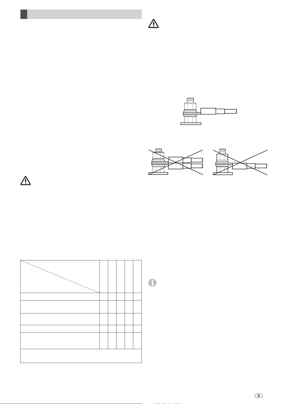
An die Anschlussbolzen +12 V (h) und -12 V (l) des Wechsel-
richters darf nur je ein Kabel mit der gecrimpten Seite nach
oben angeschlossen werden.
Der Anschluss an die Anschlussbolzen des Wechselrichters
muss in der Reihenfolge – Mutter, Scheibe, Ringöse Batterie-
anschluss, Scheibe, Sicherungsscheibe, Mutter – erfolgen.
Das Anzugsdrehmoment der Mutter beträgt 11…15 Nm.
Verpolungsgefahr: Beim Anschluss der Batteriekabel auf die
richtige Polung achten!
Der Anschluss zweier Kabel sowie der Anschluss mit der
gecrimpten Seite nach unten ist aus sicherheitstechnischen
Gründen nicht zulässig.
Der elektrische Anschluss 230 V darf nur vom Fachmann (in
Deutschland z. B. nach VDE 0100, Teil 721 oder prIEC 60364-
7-721) durchgeführt werden. Die hier abgedruckten Hinweise
sind keine Aufforderung an Laien, den elektrischen Anschluss
herzustellen, sondern dienen dem beauftragten Fachmann als
zusätzliche Information!
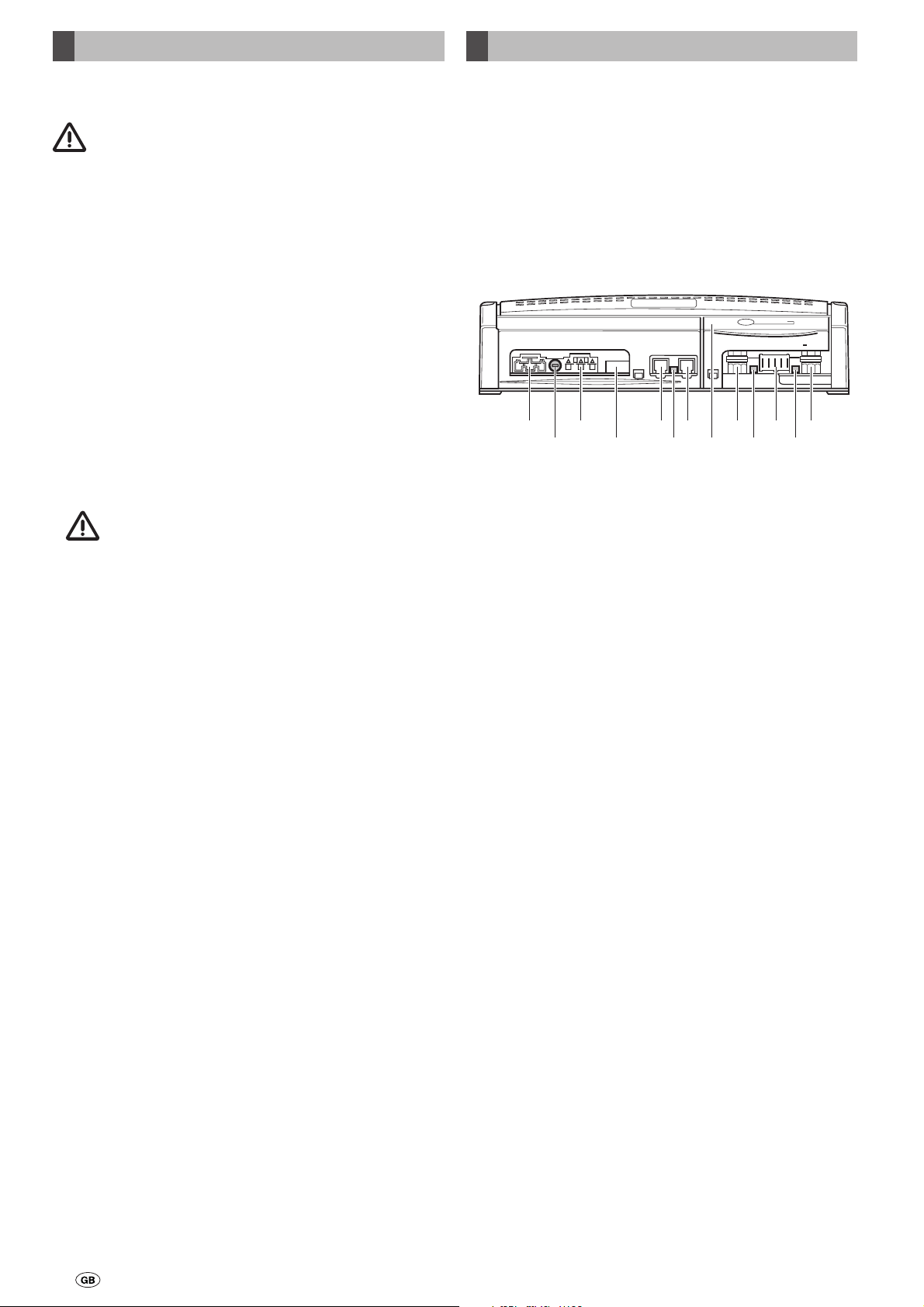
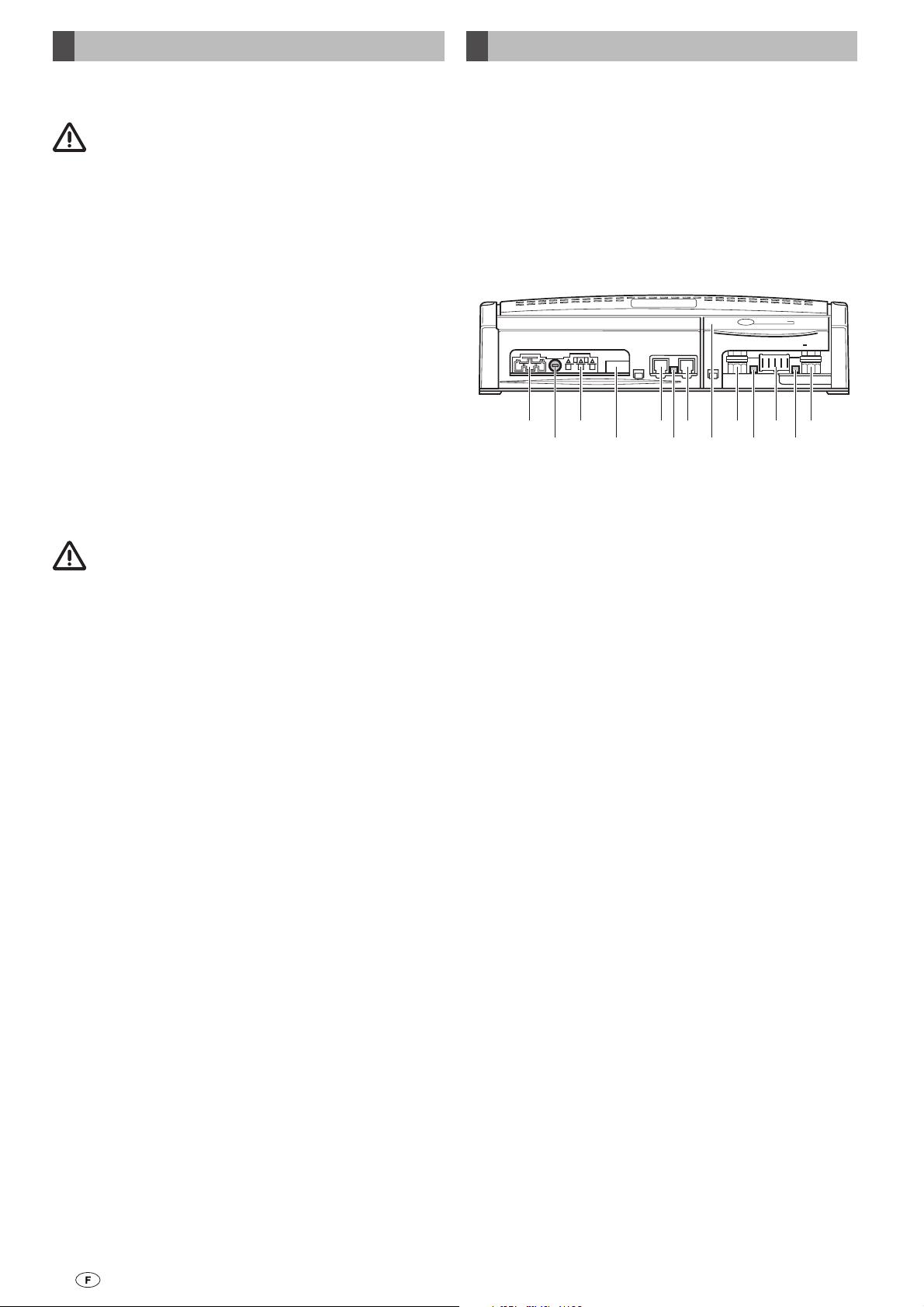
Die Anbindung des 230 V Ausgangs (c) an die vorhande-
ne 230 V Verteilung im Fahrzeug ist nicht zulässig! Der
Anschluss muss gesondert erfolgen.
Die Anschlussleitungen und Stecker dürfen keinen Kräften
ausgesetzt sein (Zugentlastung). Alle Leitungen müssen sicher
befestigt sein und dürfen sich durch Erschütterungen nicht
lockern oder lösen – sonst droht Brandgefahr!
Alle Leitungen müssen im Abstand von ca. 5 – 20 cm vom
Anschluss an den Wechselrichter am Fahrzeug befestigt wer-
den (z. B. mit Kabelschellen), um Schwingungen und Zugbe-
lastungen auszuschließen.
Die 12 V Kabel getrennt von den 230 V Leitungen
verlegen (Leerrohr). Bei der Kabelverlegung auf Scheuer-
schutz achten.

6
Truma TG 1000 sinus power inverter
Safety instruction
All repairs must be carried out by an expert!
The alternator output must be at least 110 A to provide a
Truma Saphir vario or Saphir compact air conditioning unit
with an adequate power supply.
The equipment may only be used:
– In conjunction with batteries with the specified nominal
voltage in fixed installations. (minimum battery capacity
90 Ah)
– For powering mains voltage equipment up to the specified
maximum electrical output of 1000 W.
– If it is ensured that only one consumer (max. 1000 W) is
connected. No parallel operation of multiple consum-
ers. Multiple sockets must not be used. 2-pole disconnec-
tion (L and N) must take place if transfer switches are being
used.
– In rooms that are protected from water, moisture, dust
and aggressive battery gasses, and in non-condensing
environments.
The device must never be used in locations where
there is a risk of dust or gas explosion.
– If the ambient temperature is within the permitted usage
limits.
– If the ventilation openings on the cover and the front (termi-
nal strip) are exposed and not covered by luggage, towels or
clothing etc.
Check voltage-carrying cable at regular intervals for breaks,
loose connections etc.
The device must be fully disconnected during electrical
welding work and when working on the electrical system.
The device must not be opened (dangerous high voltage may
be present, even after the battery has been disconnected).
Keep children away from the power inverter!
Operating instructions
Intended use
The TG 1000 sinus power inverter has been developed for
operating a Truma air conditioning unit (e.g. the Saphir vario
or the Saphir compact) or another consumer with electrical
power consumption of up to 1000 W.
The power inverter generates an alternating voltage (sine
wave) of 230 V ~ from a direct voltage of 12 V.
Connections
Bat
+
230 VAC
Fuse (T 6,3 A)
D+
Out
Sons+
Sons-
On
Bat
ComRemote
TG 1000 sinus
In Out
a
b
c
d
e
f
e
g
h
i
j
k
l
a= 230 V ~ mains input voltage connection via 3-pin socket
(Wago)
b= T 6.3 A fuse (always replace with identical fuse)
c= 230 V ~ output voltage connection via 3-pin plug (Wago)
d= Remote (control panel accessory connection)
e= Com connection (communication – RJ 10 plug) to air
conditioning unit
f= LED (ready)
g= Cover (to open, press and release flap of terminal strip at
controller)
h= Connecting bolt (M8), auxiliary battery positive terminal
i= LED (mains current operation)
j= 5-pin plug (5 x flat plugs 6.3 mm), pin assignment from
left to right:
D+ = 12 V signal from alternator when vehicle engine
is running
Out = 12 V output, max. 1 A, for external relay for
example, present when pin 5 is “On”
Sens+ = Starter battery positive terminal connection
(battery voltage monitoring)
Sens- = Starter battery negative terminal connection
(lower battery voltage monitoring)
On = 12 V input for switching on the power inverter
if neither the air conditioning kit nor the autarky
kit is being used (switches 12 V output “Out”)
k= LED (fault)
l= Connecting bolt (M8), auxiliary battery negative terminal

7
Operation with a Saphir vario or
Saphir compact
The ElektrikSet (electrical kit) and the KlimaSet (air condition-
ing kit) are required to connect the power inverter to the on-
board power supply and the air conditioning unit.
The power inverter automatically detects the voltage that is
present and automatically switches between the national net-
work current (230 V) and the battery (12 V).
The power inverter is controlled by the air conditioning
electronics after the air conditioning unit has been switched
on. The air conditioning unit checks the status of the power in-
verter and the connected electrical supply at short intervals (D+
of alternator, starter battery, auxiliary battery and mains).
Automatic protection function prevents starter battery
discharge (shut-off at < 11.7 V) and total discharge of
auxiliary battery (shut-off at 10.8 V)!
Possible operating modes
See air conditioning unit operating instructions for detailed
operating mode description.
Operating mode 1 (OM 1)
via auxiliary battery with 12 V
(vehicle engine off, alternator D+ is 0 V).
Operating mode 2 (OM 2)
via alternator with 12 V
(vehicle engine running, alternator provides D+ = 12 V)
Operating mode 3 (OM 3)
via national network with 230 V ~
Possible cooling levels in the individual operating modes
OM 1 OM 2 OM 3
Saphir
compact Fan operation
possible Full scope
of operation
possible
Full scope
of operation
possible
Saphir
vario Cooling mode
possible at
low setting
and fan
operation
possible
Cooling mode
possible at
low / medium
setting and
fan operation
possible
Full scope
of operation
possible
Operating a consumer via the socket
The ElektrikSet (electrical kit) and the AutarkSet (autonomy
kit) are required to connect the power inverter to the on-board
power supply and the air conditioning unit.
To operate an external 230 V unit (up to 1000 W), connect
the unit to the power inverter via the socket. The power in-
verter is switched on and off with the control panel from the
AutarkSet.
Position
=
Off / Air conditioning unit*
Position
On
a = red LED “Failure“
b = green LED = “On”
TG 1000 sinus
230 V
a
b
(*When operating with a Saphir vario or Saphir compact, the
power inverter automatically switches itself on in this position)
Only one consumer may be connected to the pow-
er inverter at any given time! The use of multiple
sockets is not permitted!
The auxiliary battery is discharged in the “On” position
(approx. 1.8 A), even if no consumer is connected.
Operating mode 1
via auxiliary battery with 12 V
(vehicle engine off, alternator D+ is 0 V).
The power inverter is shut off (red LED) in the following cases:
– Thermal overload
– Battery overvoltage and undervoltage
(Auxiliary battery < 10.5 V)
– Mains operation 230 V ~ (mains priority circuit)
Operating mode 2
via alternator with 12 V
(vehicle engine running, alternator provides D+ = 12 V)
The power inverter is shut off (red LED) in the following cases:
– Thermal overload
– Battery overvoltage and undervoltage
(Auxiliary battery < 10.5 V)
– Mains operation 230 V ~ (mains priority circuit)
No starter battery monitoring! This means that the
starter battery can be discharged if a device
with high power consumption is used for a long period!
Operating mode 3
via national network with 230 V ~
If the 230 V ~ national network fails, the power inverter is
automatically switched to operating mode 1.
Operation with Saphir vario, Saphir
compact or consumer via the socket
The ElektrikSet (electrical kit), the KlimaSet (air conditioning
kit), the AutarkSet (autonomy kit) and the SwitchboxSet
(switchbox kit) are required to connect the power inverter to
the on-board power supply, the air conditioning unit and the
socket.
The air conditioning unit (Saphir vario or Saphir compact) can
be directly operated, or an external device can be operated via
the socket.
Switching over takes place using the control panel in the
AutarkSet.
– Position switches off.
The air conditioning unit and the power inverter are
switched on and off in this position using the remote
handset.
See section “Operating with a Saphir vario or
Saphir compact” for operating mode description.
– Position switches to operation of a consumer via the
socket.
See section “Operating a consumer via the socket” for
operating mode description.

8
Technical Data
Dimensions
(L x W x H)
300 x 160 x 72 mm
Weight
Approx. 2.0 kg
Protection class
IP20
Input voltage
10.5 V to 14.8 V DC voltage (auxiliary battery)
Output power
1000 W at an ambient temperature of 45 °C
(continuous operation) with overload protection
Output voltage
230 V ± 5 % AC voltage (sine wave)
Output frequency
50 Hz
Power consumption with AC/DC converter switched on
without load
approx. 1.8 A
with load
up to 100 A
Efficiency with nominal output of 1000 W
approx. 90 %
Protection functions
Overtemperature, overvoltage/undervoltage at input,
overload shut-off at output
Deployment range
-20 °C to +55 °C
Fuse
T 6.3 A
Certification
The Truma TG 1000 sinus power inverter has been checked
for electrical safety in accordance with EN 60335 part 1 and
60335-2-29 and complies with EMC directive 89/336/EEC and
directive 72/245/EEC, with annexes 2004/104/EC and 2005/83/
EC
and bears the type approval number:
e1 03 4700
Right to effect technical modifications reserved!
Manufacturer’s terms of warranty
1. Case of warranty
The manufacturer grants a warranty for malfunctions in the
appliance which are based on material or production faults.
In addition to this, the statutory warranty claims against the
seller remain valid.
A claim under warranty shall not pertain:
– for parts subject to wear and in cases of natural wear and
tear,
– as a result of using parts that are not original Truma parts in
the units,
– as a consequence of failure to respect Truma instructions
for installation and use,
– as a consequence of improper handling,
– as a consequence of improper transport packing, not
arranged by Truma.
2. Scope of warranty
The warranty is valid for malfunctions as stated under
item 1, which occur within 24 months after conclusion of
the purchase agreement between the seller and the final
consumer. The manufacturers will make good such defects
by subsequent fulfilment, i.e. at their discretion either by
repair or replacement. In the event of manufacturers provid-
ing service under warranty, the term of the warranty shall not
recommence anew with regard to the repaired or replaced
parts; rather, the old warranty period shall continue to run.
More extensive claims, in particular claims for compensatory
damages by purchasers or third parties, shall be excluded.
This does not affect the rules of the product liability law.
The manufacturer shall bear the cost of employing the Truma
customer service for the removal of a malfunction under war-
ranty – in particular transportation costs, travelling expenses,
job and material costs, as long as the service is carried out in
Germany. The warranty does not cover customer service work
in other countries.
Additional costs based on complicated removal and installa-
tion conditions of the appliance (e.g. removal of furniture or
parts of the vehicle body) do not come under warranty.
3. Raising the case of warranty
The manufacturer's address is:
Truma Gerätetechnik GmbH & Co. KG,
Wernher-von-Braun Strasse 12,
85640 Putzbrunn.
In Germany, always notify the Truma Service Centre if prob-
lems are encountered; in other countries the relevant service
partners should be contacted (see Truma Service Booklet
or www.truma.com). Any complaints are to be described in
detail. In addition, the properly completed guarantee certifi-
cate is to be presented, or the factory number of the unit and
the date of purchase given.
To avoid transport damage, the device may only be dispatched
after agreement with the Truma Service Centre in Germany or
with the particular service partner concerned abroad. The risk
for possible transport damage will otherwise be borne by the
consignor.
If it is a case of warranty, the factory shall bear the cost for
the delivery to the factory and the cost for returning the ap-
pliance to the customer. If the damage is deemed not to be
a warranty case, the manufacturer shall notify the customer
and shall specify repair costs which shall not be borne by the
manufacturer; in this case, the customer shall also bear the
shipping costs.

9
Installation instructions
Selecting a location
The power inverter should preferably be installed in the vicin-
ity of the auxiliary battery in order keep the 12 V connecting
cable as short as possible.
The power inverter must be installed in a horizontal position, and
must not be screwed to the wall of the vehicle (suspended).
The installation site must provide adequate air circulation
within a larger area (interior of vehicle, garage etc.). Air for
cooling the power converter enters via the ventilation slots
in the cover, and air leaves the inverter via the front (terminal
strip). There must be clearance of at least 20 cm around the
air inlet and outlet.
The installation site must not heat up to more than 55º C due
to the heat generated by the power converter and other heat
sources (risk of overheating, malfunction).
Installation in confined and/or closed spaces can cause the
power inverter to overheat due to inadequate cooling.
Installation
The power inverter must be installed in compliance with
VDE 0100, part 721 or prIEC 60364-7-721.
Ensure that no voltage is present when the power
inverter is connected.
The equipment is attached at the side using the two provided
screws (depending on the surface, use different suitable
screws to secure the equipment properly if necessary).
The electrical kit is needed to make the electrical connection
of the TG 1000 sinus power inverter in all cases. One or more
additional cable sets are required depending on the purpose
of use (see table).
Possible combinations of the TG 1000 sinus
and the different cable sets
TG 1000 sinus
ElektrikSet
KlimaSet
AutarkSet
SwitchboxSet
No connecting cable included x
Connection to electrical
on-board system of vehicle
xx*
Intelligent operation of Saphir vario
or Saphir compact air conditioning
system
xx*x
230 V supply via a socket x x* x
Operation of Saphir vario,
Saphir compact or consumer via a
socket
xx*x x x
* The D+ InverterSet may also be required for vehicles with a
negative, non-loadable D+ signal.
A connecting diagram and a description of the connection are
provided with the respective kit.
Electrical connection
Failure to install the equipment properly (e.g.
12 V cable with a cross-section that is too small,
inadequate connections etc.) may cause the cables or
contacts to overheat. Risk of fire!
Only one cable must be connected to each of the +12 V (h)
and -12 V (l) connecting bolts of the power inverter, with the
crimped side on top.
The connection to the power inverter connecting bolts must
be made in the order nut, washer, battery connection ring eye,
washer, securing washer, nut. The nut tightening torque is
11 to 15 Nm.
Risk of polarity inversion: Please ensure that the polarity is
correct when the battery cables are connected!
Connecting two cables or making the connection with the
crimped side underneath is not permitted for technical safety
reasons.
The 230 V electrical connection must always be made
by an expert (in accordance with VDE 0100, part 721 or
prIEC 60364-7-721, for example, in Germany). The instructions
shown here do not constitute a request for non-experts to
make the electrical connection, but serve as additional infor-
mation for an expert who is employed to do the work!
Connecting the 230 V output (c) to the existing 230 V
distributor in the vehicle is not permitted! The connec-
tion must be made separately.
The connecting cables and plugs must not be subjected to
force (strain relief). All cables must be securely attached and
must not become loose or disconnected due to vibration –
otherwise risk of fire!
All cables must be secured at a distance of approx. 5 – 20 cm
from the connection to the power inverter in the vehicle (e. g.
with cable clamps) in order to prevent vibration and strain.
The 12 V cables must be routed separately from the
230 V cables (empty tube). Please pay attention to chaf-
ing protection when routing the cables.

10
Convertisseur Truma TG 1000 sinus
Informations concernant la sécurité
Seul un spécialiste est autorisé à procéder à des
réparations.
La puissance de l‘alternateur doit être d‘au moins 110 A pour
une alimentation en courant suffisante d‘un climatiseur Truma
Saphir vario ou Saphir compact.
L’utilisation est réservée uniquement aux conditions
suivantes :
– Sur des batteries à la tension nominale indiquée dans des
systèmes installés à poste fixe. (respecter la capacité
minimale de batterie de 90 Ah).
– Pour l’alimentation d’un appareil fonctionnant sur la tension
du secteur jusqu’à la puissance électrique maximale
indiquée de 1000 W.
– Être sûr qu‘un seul consommateur (1000 W maximum) est
raccordé. Ne pas faire fonctionner plusieurs consom-
mateurs parallèlement. Ne pas utiliser de multiprise. Cou-
per le courant sur les 2 pôles (L et N) en cas d‘utilisation de
commutateurs de secteur.
– À l‘intérieur de locaux protégés contre l‘eau, l‘humidité, la
poussière et les gaz de batteries agressifs, ainsi que dans un
environnement ne produisant pas de condensation.
Ne jamais utiliser l‘appareil dans des endroits présen-
tant un risque d‘explosion de gaz ou de poussière.
– La température ambiante doit se trouver dans la plage
d‘utilisation autorisée.
– Les ouvertures de ventilation sur le couvercle et la façade
(barre de connexion) doivent être libres et non obturées par
des bagages, serviettes, vêtements etc.
Vérifier régulièrement les câbles conducteurs de tension à la
recherche de cassures, connexions desserrés etc.
L‘appareil doit être séparé de toutes les connexions lors de
travaux de soudage électrique et de travaux sur l‘installation
électrique.
Il est interdit d‘ouvrir l‘appareil (même séparé de la batterie,
des tensions dangereusement élevées peuvent encore se
produire).
Maintenir les enfants à distance du convertisseur !
Mode d‘emploi
Utilisation prévue
Le convertisseur TG 1000 sinus a été développé pour le fonc-
tionnement d’un climatiseur Truma (par exemple Saphir vario
ou Saphir compact) ou d’un autre consommateur jusqu’à
1000 W de puissance absorbée.
À partir d’une tension continue de 12 V, le convertisseur
génère une tension alternative de 230 V ~ (sinusoïdale).
Connexions
Bat
+
230 VAC
Fuse (T 6,3 A)
D+
Out
Sons+
Sons-
On
Bat
ComRemote
TG 1000 sinus
In Out
a
b
c
d
e
f
e
g
h
i
j
k
l
a= connexion tension d‘entrée 230 V ~ secteur via douille
3 pôles (Wago)
b= fusible T 6,3 A (remplacement uniquement contre un
fusible de construction identique)
c= connexion tension de sortie 230 V ~ via fiche 3 pôles
(Wago)
d= Remote (connexion accessoire de pièce de commande)
e= prise Com (fiche de communication RJ 10) pour le
climatiseur
f= DEL (ordre de marche)
g= recouvrement (pour ouvrir le couvercle de la barre
de connexions sur la commande, le presser et le
déverrouiller)
h= boulon de connexion (M8) du pôle « plus » de la batte-
rie complémentaire
i= DEL (mode de fonctionnement sur secteur)
j= fiche 5 pôles (5 x fiches plates 6,3 mm) affectation des
broches de la gauche vers la droite :
D+ = signal 12 V de l‘alternateur lorsque le
moteur du véhicule tourne
Out = sortie 12 V max. 1 A, par exemple pour un
relais externe, dépend de la broche 5 « on »
Sens+ = connexion pour le pôle « plus » de la
batterie de démarrage
(surveillance de la tension de batterie )
Sens- = connexion pour le pôle « moins » de la
batterie de démarrage
(surveillance de la tension de batterie
inférieure)
On = entrée 12 V pour la mise en marche du
convertisseur lorsque ni le kit climatisation
ni le kit autarcie n‘est utilisé
(met la sortie 12 V sur « out »)
k= DEL (défaillance)
l= boulon de connexion (M8) du pôle « moins » de la
batterie complémentaire
Fonctionnement avec un Saphir vario ou
un Saphir compact
Le ElektrikSet (kit électricité) et le KlimaSet (kit climatisation)
sont nécessaires pour la connexion du convertisseur au ré-
seau électrique de bord.
Le convertisseur détecte automatiquement la tension pré-
sente et commute automatiquement entre le courant secteur
(230 V) et la batterie (12 V).

11
Le convertisseur est piloté par le système électronique
du climatiseur après la mise en marche du climatiseur.
Le climatiseur vérifie les états du convertisseur et de l‘alimen-
tation électrique raccordée selon des intervalles de temps
brefs (borne D+ de l‘alternateur, batterie de démarrage, batte-
rie complémentaire et secteur).
Fonction automatique de protection contre la décharge
de la batterie de démarrage (déconnexion si < 11,7 V) et
la décharge profonde de la batterie complémentaire
(déconnexion si < 10,8 V).
États de fonctionnement possibles
Pour la description détaillée des états de fonctionnement, voir
le mode d’emploi du climatiseur.
État de fonctionnement 1 (EF 1)
via la batterie complémentaire en 12 V
(moteur du véhicule arrêté, D+ de l’alternateur = 0 V).
État de fonctionnement 2 (EF 2)
via l’alternateur en 12 V
(moteur du véhicule en marche, l’alternateur fournit du 12 V à D+)
État de fonctionnement 3 (EF 3)
via secteur en 230 V ~
Paliers de refroidissement possibles dans les différents
états de fonctionnement
EF 1 EF 2 EF 3
Saphir
compact Fonctionne-
ment ventila-
teur possible
Fonctionne-
ment intégral
possible
Fonctionne-
ment intégral
possible
Saphir
vario Le mode de ra-
fraîchissement
est possible
selon le palier
bas. Le mode
de ventilation
est également
possible.
Le mode de ra-
fraîchissement
est possible
selon le palier
bas / moyen.
Le mode de
ventilation est
également
possible.
Fonctionne-
ment intégral
possible
Fonctionnement d’un consommateur via
la prise de courant
Le ElektrikSet (kit électricité) et le AutarkSet (kit autarcie) sont
nécessaires pour la connexion du convertisseur au réseau
électrique de bord et à la prise de courant.
Pour le fonctionnement d’un appareil 230 V externe (jusqu’à
1000 W), le connecter au convertisseur via la prise de courant.
Le convertisseur est mis en marche et arrêté à l’aide de la
pièce de commande du AutarkSet.
Position
=
arrêt / climatiseur*
Position
= marche
a = DEL rouge, « panne »
b = DEL verte « fonctionnement »
TG 1000 sinus
230 V
a
b
(* en cas de fonctionnement d‘un Saphir vario ou d‘un
Saphir compact, le convertisseur se met automatiquement
en marche dans cette position)
Ne jamais connecter plus d’un consommateur au
convertisseur. L’utilisation de multiprises est
interdite.
En position « marche », la batterie complémentaire se
décharge (environ 1,8 A), même si aucun consommateur
n’est connecté.
État de fonctionnement 1
via la batterie complémentaire en 12 V
(moteur du véhicule arrêté, D+ de l’alternateur = 0 V).
Le convertisseur s’arrête (la DEL rouge s’allume) dans les cas
suivants :
– surcharge thermique ;
– surtension ou sous-tension de la batterie
(batterie complémentaire < 10,5 V)
– fonctionnement secteur 230 V ~
(commutation prioritaire du secteur)
État de fonctionnement 2
via l’alternateur en 12 V
(moteur du véhicule en marche, l’alternateur fournit D+ en 12 V)
Le convertisseur s’arrête (la DEL rouge s’allume) dans les cas
suivants :
– surcharge thermique ;
–-surtension ou sous-tension de la batterie
(batterie complémentaire < 10,5 V)
– fonctionnement secteur 230 V ~
(commutation prioritaire du secteur)
Pas de surveillance de la batterie de démarrage.
Cela signifie que la batterie peut se décharger en
cas de fonctionnement prolongé d’un appareil à forte
consommation de courant.
État de fonctionnement 3
via secteur en 230 V ~
En cas de panne du secteur 230 V ~, le convertisseur est
automatiquement mis dans l’état de fonctionnement 1.
Fonctionnement avec Saphir vario ou
Saphir compact ou d’un consommateur
via la prise de courant
Le ElektrikSet (kit électricité), le KlimaSet (kit climatisation), le
AutarkSet (kit autarcie) et le SwitchboxSet (kit switchbox) sont
nécessaires pour la connexion du convertisseur au réseau
électrique de bord, au climatiseur et à la prise de courant.
Il est possible de faire fonctionner directement le climatiseur
(Saphir vario ou Saphir compact) ou un appareil externe (via la
prise de courant).
La commutation a lieu avec la pièce de commande du
AutarkSet :
– Position arrêt.
Dans cette position, le climatiseur est mis en marche ou
éteint en même temps que le convertisseur au moyen de la
télécommande.
États de fonctionnement : conformément à la description
sous « Fonctionnement avec un Saphir vario ou un
Saphir compact ».
– Position commutation dans le mode d’un consommateur
via la prise de courant.
États de fonctionnement : conformément à la description
sous « Fonctionnement d’un consommateur via la prise de
courant ».

12
Caractéristiques techniques
Dimensions
(L x l x H)
300 x 160 x 72 mm
Poids
Env. 2,0 kg
Type de protection
IP20
Tension d‘entrée
10,5 V…14,8 V de tension continue (batterie complémentaire)
Puissance de sortie
1000 W à 45 °C de température ambiante (fonctionnement
continu) avec protection contre les surcharges.
Tension de sortie
230 V ± 5 % de tension alternative (sinus)
Fréquence de sortie
50 Hz
Consommation de courant lorsque le transducteur
AC/DC est en marche sans charge
env. 1,8 A
avec charge
jusqu’à 100 A
Degré de rendement à puissance nominale de 1000 W
env. 90 %
Fonctions de protection
surtempérature, surtension et sous-tension sur l‘entrée,
déconnexion de surcharge sur la sortie
Plage d‘utilisation
-20 °C…+55 °C
Fusible
T 6,3 A
Homologation
La sécurité électrique du convertisseur Truma TG 1000 sinus a
été contrôlée selon EN 60335 partie 1 et EN 60335-2-29
et répond à la directive CEM 89/336/CEE et à la directive
72/245/CEE, avec les compléments 2004/104/CE et
2005/83/CE et porte le numéro d‘autorisation de type
e1 03 4700
Sous réserve de modifications techniques !
Déclaration de garantie du fabricant
1. Cas de garantie
Le fabricant concède une garantie pour des carences de
l’appareil imputables à des défauts du matériau ou de la
fabrication. En outre, le recours légal en garantie auprès du
vendeur reste valable.
La garantie ne s’applique plus :
– pour les pièces d’usure et en cas d’usure naturelle,
– suite à l'utilisation de pièces autres que des pièces
originales Truma dans les appareils,
– en cas de non-respect des instructions de montage et du
mode d’emploi Truma,
– en cas d’utilisation non conforme,
– en cas d’emballage de transport inapproprié et non ordonné
par Truma.
2. Prestations de garantie
La garantie couvre les carences dans le sens de l’article 1, se
manifestant dans les 24 mois suivant la conclusion du contrat
d’achat entre le vendeur et l’utilisateur. Le fabricant procédera
à la remise en ordre de tels défauts, c’est-à-dire au choix par
la livraison d’un appareil de rechange ou par une réparation.
Si le fabricant réalise une prestation de garantie, le délai de
garantie concernant les pièces réparées ou remplacées ne
recommence pas du début, l’ancien délai continue à courir.
Des prétentions plus poussées, en particulier des prétentions
à dommages-intérêts de l’acheteur ou d’un tiers, sont exclues.
Les dispositions de la législation sur la responsabilité sur le
produit ne sont pas mises en cause.
Les frais de mise à contribution du service après-vente usine
Truma pour remédier à une carence couverte par la garantie,
en particulier les frais de transport, de manutention, de main-
d’oeuvre et de matériel, sont à la charge du fabricant, pour
autant que le SAV intervient sur le territoire de la République
Fédérale d’Allemagne. La garantie ne couvre pas les
interventions de service après-vente dans les autres pays.
Des frais supplémentaires dus à des difficultés de dépose et
de repose de l’appareil (par ex. démontage et remontage de
meubles ou de parties de la carrosserie) ne sont pas reconnus
en tant que prestation de garantie.
3. Invocation du cas de garantie
Les coordonnées du fabricant sont les suivantes :
Truma Gerätetechnik GmbH & Co. KG,
Wernher-von-Braun-Straße 12,
85640 Putzbrunn.
En Allemagne, toujours appeler le centre de SAV Truma en cas
de dysfonctionnement. Dans les autres pays, les partenaires
de service après-vente correspondants se tiennent à disposi-
tion (voir livret de service Truma ou www.truma.com). Toutes
les réclamations doivent être signifiées avec de plus amples
précisions. En outre, vous devez présenter votre justificatif
de garantie rempli en bonne et due forme ou bien indiquer le
numéro de fabrication de l’appareil, ainsi que sa date d’achat.
Pour éviter les dommages dus au transport, l’appareil ne peut
être expédié qu’après concertation de la centrale de service
Truma en Allemagne ou du partenaire de service correspon-
dant à l’étranger. Faute de quoi l’expéditeur supportera le
risque d’éventuels dégâts dus au transport.
Dans le cas de garantie, l’usine prend en charge les frais d’en-
voi dans les deux sens. Sinon, l’usine en avise le client et lui
communique le montant du coût de la réparation qu’il devra
supporter; dans ce cas, les frais d’expédition sont également à
la charge du client.

13
Instructions de montage
Choix de l‘emplacement
Le convertisseur doit être monté de préférence à proximité de
la batterie complémentaire afin de garder le câble d‘alimenta-
tion 12 V court.
Le convertisseur doit être monté couché (à l‘horizontale), il est
interdit de le visser à la paroi du véhicule (suspendu).
L‘emplacement du montage doit être choisi de manière à
assurer une circulation d‘air suffisante par rapport à un local
de grande taille (intérieur du véhicule, garage, etc.). Pour le
refroidissement du convertisseur, l‘entrée d‘air est assurée via
les ouïes de ventilation sur le couvercle, la sortie d‘air en faça-
de (barre de connexion). L‘espace libre au-dessus de l‘entrée
et de la sortie d‘air doit être d‘au moins 20 cm.
Les émissions de chaleur du convertisseur et les autres sour-
ces de chaleur ne doivent pas faire monter la température de
l‘emplacement de montage à plus de 55 °C (risque de
sur-chauffe et de dysfonctionnement).
Le montage dans un local exigu et/ou fermé peut provoquer
un défaut de refroidissement et donc une surchauffe du
convertisseur.
Montage
Le montage du convertisseur doit être réalisé selon la norme
VDE 0100, partie 721 ou prIEC 60364-7-721.
S‘assurer de l‘absence de tension lors de la connexion
du convertisseur.
La fixation est latérale avec les deux vis jointes (en fonction du
support, utiliser le cas échéant d’autres vis plus appropriées
pour une fixation sûre).
Le kit électrique est toujours nécessaire pour la connexion élec-
trique du convertisseur TG 1000 sinus. Un ou plusieurs kits de
câbles sont nécessaires en plus selon l’utilisation (voir tableau).
Possibilités de combinaison convertisseur
TG 1000 sinus et des différents kits de câbles
TG 1000 sinus
ElektrikSet
KlimaSet
AutarkSet
SwitchboxSet
Aucun câble de connexion n‘est fourni x
Intégration au système électrique de
bord du véhicule
xx*
Fonctionnement intelligent de la
climatisation Saphir vario ou
Saphir compact
xx*x
Prélèvement 230 V via une prise de
courant
xx* x
Fonctionnement du Saphir vario ou
Saphir compact ou d’un consomma-
teur via une prise de courant
xx*x x x
* Le kit « inverseur D+ » est le cas échéant nécessaire pour
les véhicules avec un signal D+ négatif inapte à supporter
une charge.
Un schéma de connexion et une description de la connexion
sont joints au kit correspondant.
Connexion électrique
Risque de surchauffe des câbles ou des contacts
en cas d’installation impropre (par exemple câbles
12 V de section trop petite, connexions insuffisantes
etc.). Risque d’incendie.
Il faut connecter seulement un câble sur chacune des vis de
connexion +12 V (h) et -12 V (l) du convertisseur avec le côté
serti vers le haut.
La connexion aux vis de connexion du convertisseur doit être
effectuée dans l’ordre suivant : écrou, rondelle, cosse à œillet
de connexion de batterie, rondelle, rondelle d’arrêt, écrou. Le
couple de serrage de l’écrou est de 11...15 Nm.
Risque d’inversion de polarité : veiller à la bonne
polarité lors de la connexion des câbles de batterie !
Pour des raisons techniques de sécurité, il est interdit de
connecter deux câbles ainsi que de faire une connexion avec
le côté serti vers le bas.
Seul un spécialiste est autorisé à réaliser la connexion élec-
trique 230 V (en Allemagne par exemple selon la norme
VDE 0100, partie 721 ou prIEC 60364-7-721). Les consignes
mentionnées ici ne sont pas une invitation à des amateurs
pour qu’ils établissent eux-mêmes la connexion électrique. Il
s’agit d’une information supplémentaire destinée au spécialiste
mandaté pour cette tâche.
L’intégration de la sortie 230 V (c) à la distribution
230 V présente dans le véhicule est interdite. La
connexion doit avoir lieu à part.
Les câbles d’alimentation et les fiches ne doivent être soumis
à aucune force (décharge de traction). Tous les conducteurs
doivent être fixés avec fiabilité. Les chocs ne doivent pas les
desserrer ou les détacher. Risque d’incendie.
Afin d’éviter des vibrations et des sollicitations par traction,
tous les conducteurs doivent être fixés au véhicule (par
exemple avec des brides de câble) à environ 5 à 20 cm de la
connexion du convertisseur.
Poser les câbles 12 V séparément des conducteurs 230 V
(gaine ICT). Lors de leur pose, veiller à ce que les câbles
soient protégés des frottements.

14
Invertitore Truma TG 1000 sinus
Avvertenze di sicurezza
Eventuali riparazioni devono essere eseguite solamente
da personale qualificato!
Per alimentare adeguatamente un condizionatore Saphir vario
o Saphir compact di Truma, la potenza dell‘alternatore deve
essere pari ad almeno 110 A.
L’apparecchio può essere utilizzato esclusivamente alle
seguenti condizioni:
– Con batterie della tensione nominale indicata in sistemi a
installazione fissa (capacità minima batterie 90 Ah).
– Per l’alimentazione di apparecchi collegati alla rete fino alla
potenza elettrica massima indicata di 1000 W.
– Quando si è accertato che è collegata solamente un‘utenza
(max. 1000 W).
Non far funzionare in parallelo più
utenze.
Non utilizzare prese multiple. In caso di utilizzo di
commutatori di rete, i 2 poli (L e N) devono essere staccati.
– In locali, protetto contro acqua, umidità, polvere e gas
aggressivi di batterie nonché in ambiente privo di condensa.
Non utilizzare mai l‘apparecchio in luoghi a rischio di
esplosione dovuta a gas o polveri.
– Se la temperatura ambiente rientra nel campo d‘impiego
consentito.
– Se i fori di ventilazione sul coperchio e sul lato frontale
(basetta) sono liberi e non sono ostruiti da bagagli,
asciugamani o abiti ecc.
Verificare periodicamente l‘assenza di rotture, connessioni
lasche ecc. dei cavi sotto tensione.
In caso di saldature elettriche e lavori all‘impianto elettrico,
staccare tutti i collegamenti dell‘apparecchio .
Non aprire l‘apparecchio (alte tensioni pericolose possono
essere presenti anche dopo aver scollegato la batteria).
Tenere l‘invertitore lontano dalla portata dei bambini!
Istruzioni per l‘uso
Scopo d’impiego
L’invertitore TG 1000 sinus è stato progettato per il fun-
zionamento dei condizionatori Truma (Saphir vario o
Saphir compact) o di altre utenze fino a 1000 W di potenza
elettrica assorbita.
L’invertitore genera una tensione alternata di 230 V ~ (seno)
partendo da una tensione continua di 12 V.
Collegamenti
Bat
+
230 VAC
Fuse (T 6,3 A)
D+
Out
Sons+
Sons-
On
Bat
ComRemote
TG 1000 sinus
In Out
a
b
c
d
e
f
e
g
h
i
j
k
l
a= Connessione tensione in ingresso 230 V ~ dalla rete
locale tramite connettore a 3 poli (Wago)
b= fusibile T 6,3 A
(sostituibile solo con prodotti dello stesso tipo )
c= Connessione tensione in uscita 230 V ~ tramite spina
tripolare (Wago)
d= remote (collegamento quadro di comando-accessori)
e= collegamento Com (comunicazione - connettore RJ 10)
al condizionatore
f= LED (standby)
g= Coperchio (per sbloccare e aprire , premere lo sportello
della morsettiera sulla centralina di comando)
h= Vite di connessione (M8) per polo positivo batteria
supplementare
i= LED (funzionamento con rete locale)
j= Connettori a 5 poli (5 spine piatte da 6,3 mm) occupa-
zione connettori da sinistra a destra:
D+ = Segnale 12 V proveniente dall‘alternatore
con motore veicolo in moto
Out = Uscita 12 V max. 1 A, p.es. per relè ester-
no, si comporta come pin 5 «On»
Sens+ = collegamento per il polo positivo della
batteria di avviamento
(controllo della tensione batteria)
Sens- = collegamento per il polo negativo della
batteria di avviamento
(controllo della tensione batteria inferiore)
On = Ingresso a 12 V per l‘accensione dell‘inver-
titore, quando non vengono utilizzati né il
kit Condizionamento, né il kit Autonomia
(commuta l’uscita a 12 V «out»)
k= LED (guasto)
l= Vite di connessione (M8) per polo negativo batteria
supplementare

15
Funzionamento con un Saphir vario o
Saphir compact
Per collegare l’invertitore alla rete di bordo e al condizionatore,
sono necessari gli accessori ElektrikSet (set elettricità) e
KlimaSet (set condizionamento).
L’invertitore riconosce automaticamente la tensione presente
ed effettua la commutazione tra rete locale (230 V) e batteria
(12 V) in modo autonomo.
L‘invertitore viene attivato dopo che la centralina elettro-
nica del condizionatore ha provveduto ad accendere il
condizionatore. Il condizionatore verifica, a brevi intervalli di
tempo, gli stati dell‘invertitore e dell‘alimentazione elettrica
collegata (D+ dell‘alternatore, batteria di avviamento, batteria
supplementare e rete locale).
Funzione di protezione automatica prima che la batteria
di avviamento si scarichi (spegnimento ad una tensio-
ne < 11,7 V) e che la batteria supplementare arrivi al
completo esaurimento (spegnimento ad una tensione
< 10,8 V)!
Stati di funzionamento possibili
Per una descrizione dettagliata degli stati di funzionamento,
leggere le istruzioni per l’uso del condizionatore.
Stato di funzionamento 1 (BZ 1)
tramite la batteria supplementare con 12 V
(motore veicolo spento, D+ dell’alternatore = 0 V).
Stato di funzionamento 2 (BZ 2)
tramite l’alternatore con 12 V
(con motore veicolo acceso, l’alternatore fornisce D+ = 12 V)
Stato di funzionamento 3 (BZ 3)
tramite rete locale a 230 V ~
Modalità di raffreddamento possibili per i singoli stati di
funzionamento
BZ 1 BZ 2 BZ 3
Saphir
compact Funzionamen-
to ventilatore
possibile
Funzionamen-
to a pieno
regime
possibile
Funzionamento
a pieno regime
possibile
Saphir
vario Modalità di
raffreddamen-
to al livello
basso e fun-
zionamento
del ventilatore
possibili
Modalità di
raffreddamen-
to al livello
basso / medio
e funziona-
mento del
ventilatore
possibili
Funzionamento
a pieno regime
possibile
Funzionamento di un’utenza tramite presa
di corrente
Per collegare l’invertitore alla rete di bordo e alla presa, sono
necessari gli accessori ElektrikSet (set elettricità) e AutarkSet
(set autonomia).
Per il funzionamento di un apparecchio esterno a 230 V (fino a
1000 W), questo viene collegato all’invertitore tramite la presa.
L’invertitore si accende e si spegne con il quadro di comando
del AutarkSet.
Posizione =
Off / condizionatore*
Posizione = On
a = LED rosso, «guasto»
b = LED verde «in funzione»
TG 1000 sinus
230 V
a
b
(* durante il funzionamento di un Saphir vario o
Saphir compact, in questa posizione l‘invertitore si accende
automaticamente)
Collegare sempre una sola utenza all’invertitore!
non è consentito utilizzare prese multiple!
Nella posizione «ON”, la batteria supplementare si scari-
ca (1,8 A circa) anche se non sono collegate utenze.
Stato di funzionamento 1
tramite la batteria supplementare con 12 V
(motore veicolo spento, D+ dell’alternatore = 0 V)
L’invertitore si spegne (LED rosso acceso) quando:
– sovraccarico termico
– sovra o sottotensione della batteria
(la tensione della batteria supplementare è < 10,5 V)
– funzionamento di rete a 230 V ~
(inserzione prioritaria di rete)
Stato di funzionamento 2
tramite l’alternatore con 12 V
(con motore veicolo acceso, l’alternatore fornisce D+ = 12 V)
L’invertitore si spegne (LED rosso acceso) quando:
– sovraccarico termico
– sovra o sottotensione della batteria
(la tensione della batteria supplementare è < 10,5 V)
– funzionamento di rete a 230 V ~
(inserzione prioritaria di rete)
Nessun controllo della batteria di avviamento!
Ciò significa che, in caso di funzionamento prolun-
gato di un apparecchio con maggiore assorbimento di
corrente, la batteria di avviamento può scaricarsi!
Stato di funzionamento 3
tramite rete locale con 230 V ~
In caso di interruzione della rete locale a 230 V ~, l’invertitore
si attiva automaticamente nello stato di funzionamento 1.
Funzionamento con Saphir vario e
Saphir compact o di un’utenza tramite
presa di corrente
Per collegare l’invertitore alla rete di bordo, al condizionato-
re e alla presa sono necessari gli accessori ElektrikSet (set
elettricità), KlimaSet (set condizionamento), AutarkSet (set
autonomia) e SwitchboxSet (set switchbox).
Si può far funzionare direttamente il condizionatore (Saphir vario
e Saphir compact) o – tramite la presa – un apparecchio
esterno.
La commutazione avviene con il quadro di comando del
AutarkSet:
– Posizione spegnimento. In questa posizione, il condi-
zionatore (insieme all’invertitore) si accende o spegne con il
telecomando.
Stati di funzionamento come descritti per «Funzionamento
con un Saphir vario o Saphir compact”.
– Posizione commutazione nel funzionamento di un’utenza
tramite presa di corrente.
Stati di funzionamento come descritti in «Funzionamento di
un’utenza tramite presa di corrente”.

16
Dati tecnici
Dimensioni
L x P x A.:
300 x 160 x 72 mm
Peso
ca. 2,0 kg
Tipo di protezione
IP20
Tensione d‘ingresso
tensione continua 10,5 V…14,8 V (batteria supplementare)
Potenza di uscita
1000 W con temperatura ambiente di 45 °C (funzionamento
continuo) con protezione contro i sovraccarichi
Tensione d‘uscita
tensione alternata 230 V ± 5 % (seno)
Frequenza di uscita
50 Hz
Corrente assorbita con convertitore AC/DC
senza carico
1,8 A circa
con carico
fino a 100 A
Rendimento alla potenza nominale 1000 W
ca. 90 %
Funzioni di protezione
sovratemperatura , sovra/sottotensione all‘ingresso,
interruttore di sovraccarico sull‘uscita
Campo d‘impiego
-20 °C…+55 °C
Fusibile
T 6,3 A
Omologazione
L‘inverter Truma TG 1000 sinus è omologato per sicurezza
elettrica secondo le norme EN 60335 Parte 1 e EN 60335-2-29
e soddisfa la direttiva EMC 89/336/CEE e la direttiva 72/245/CEE
con le relative integrazioni 2004/104/CE e 2005/83/CE e reca il
numero di omologazione: e1 03 4700
Con riserva di modifiche tecniche!
Dichiarazione di garanzia della Casa Truma
1. Evento di garanzia
La Casa riconosce la garanzia per guasti dell’apparecchio,
dovuti a difetti di materiale o di produzione. Restano inalte-
rati i diritti di garanzia legali da far eventualmente valere nei
confronti del venditore.
Non si presta alcuna garanzia:
– in caso di pezzi soggetti ad usura e in caso di logoramento
naturale dovuto all’uso,
– in seguito all’utilizzo negli apparecchi di parti di ricambio
non originali Truma,
– a seguito dell’inosservanza delle istruzioni d’uso e di
montaggio Truma,
– a seguito di un utilizzo improprio,
– a seguito di un imballaggio per il trasporto improprio e non
autorizzato da Truma.
2. Campo di applicazione della garanzia
La garanzia vale per difetti di cui alla cifra 1, che si verificano
nel giro di 24 mesi dalla stipulazione del contratto di acquisto
tra il venditore e il consumatore finale. Il costruttore rimedierà
a tali guasti riparandoli, ma potrà decidere se effettuare una
riparazione o una sostituzione. Nel caso in cui il costruttore
decida di prestare garanzia, il periodo di garanzia, relativamen-
te al pezzo riparato o sostituito, non avrà inizio dal momento
della riparazione o sostituzione, bensì sarà valido il vecchio pe-
riodo di garanzia. Si escludono ulteriori rivendicazioni, in parti-
colare richieste di risarcimento danni da parte dell’acquirente
o terzi. Restano salve le norme della legge sulla responsabilità
di prodotto.
I costi del servizio di assistenza Truma, inte rvenuto per eli-
minare il difetto in garanzia, – in particolar modo i costi di
trasporto, di percorso, di lavoro e di materiale – vanno a carico
della Casa, se il servizio di assistenza interviene all’interno del
territorio federale. Gli interventi del servizio di assistenza clienti
all’estero non sono coperti dalla garanzia.
Eventuali costi aggiuntivi, dovuti a condizioni difficili di smon-
taggio e di montaggio dell’apparecchio, es. smontaggio di
parti di mobili e di carrozzeria, non possono essere riconosciuti
in garanzia.
3. Rivalsa del diritto di garanzia
L'indirizzo del produttore è il seguente:
Truma Gerätetechnik GmbH & Co. KG,
Wernher-von-Braun-Straße 12,
85640 Putzbrunn.
In Germania, in caso di guasti occorre rivolgersi, in linea di
principio, al centro di assistenza Truma; negli altri paesi, sono
disponibili i rispettivi partner per l’assistenza (v. opuscolo cen-
tri di assistenza Truma o il sito www.truma.com). I reclami de-
vono essere descritti con precisione. Inoltre, occorre presenta-
re il documento di garanzia debitamente compilato o indicare
il numero di serie e la data di acquisto della stufa.
Per evitare danni durante il trasporto, l'apparecchio può essere
spedito solo previo accordo con la sede centrale del servizio
di assistenza Truma per la Germania o con il partner addetto
all'assistenza all'estero. In caso contrario, il mittente si assume
il rischio di eventuali danni dovuti al trasporto.
In caso di garanzia lo stabilimento rileva i costi per la spedizio-
ne di andata e di ritorno. Se l’evento di garanzia non si verifica,
la Casa trasmette al cliente una segnalazione specifica, indi-
cando i costi di riparazione che la Casa non si assume; in tal
caso anche i costi di trasporto vanno a carico del cliente.

17
Istruzioni di montaggio
Scelta della posizione
Installare l‘invertitore preferibilmente in prossimità della
batteria supplementare per mantenere breve la linea di
collegamento a 12 V.
Installare l’invertitore in piano (in orizzontale), non avvitarlo alla
parete del veicolo (non appenderlo)!
Il luogo di montaggio deve essere scelto in modo da consenti-
re una sufficiente circolazione dell‘aria verso un ambiente più
grande (abitacolo del veicolo, garage ecc.). Per il raffredda-
mento dell‘invertitore, l‘aria viene introdotta attraverso feritoie
di ventilazione sul coperchio e viene espulsa dal pannello an-
teriore (basetta). Sopra l‘ingresso e l‘uscita dell‘aria va lasciato
uno spazio libero di almeno 20 cm.
La temperatura nel locale di montaggio non deve supe-
rare i 55 °C in seguito al calore prodotto dall‘invertitore e
da altre fonti di calore (pericolo di surriscaldamento e di
malfunzionamento).
Il montaggio in spazi ristretti e/o chiusi può portare al
surriscaldamento dell‘invertitore dovuto all‘insufficiente
raffreddamento.
Montaggio
Eseguire l’installazione dell’invertitore secondo la norma VDE
0100, parte 721 o prIEC 60364-7-721.
Assicurarsi che sull‘invertitore non siano presenti tensioni
al momento del collegamento.
Il fissaggio avviene di lato utilizzando le due viti in dotazione
(a seconda del fondo, servirsi eventualmente di altre viti più
idonee a garantire un fissaggio sicuro).
Per il collegamento elettrico dell’invertitore TG 1000 sinus
occorre sempre il kit Elettricità. A seconda dello scopo d’uso,
sono inoltre necessari anche uno o più set di cavi (v. tabella).
Combinazioni possibili invertitore
TG 1000 sinus con i diversi set di cavi
TG 1000 sinus
ElektrikSet
KlimaSet
AutarkSet
SwitchboxSet
Nessun cavo di collegamento in
dotazione
x
Collegamento all‘impianto elettrico di
bordo del veicolo
xx*
Funzionamento intelligente del
condizionatore Saphir vario e
Saphir compact
xx*x
Prelievo di 230 V tramite presa di
corrente
xx* x
Funzionamento di Saphir vario e
Saphir compact o di un‘utenza tramite
una presa di corrente
xx*x x x
* Per i veicoli con segnale D+ negativo non caricabile può
essere necessario anche il kit Commutatore.
Ogni set è completo di schema di collegamento e relativa
descrizione.
Collegamento elettrico
In caso di installazione impropria (p. es. cavo da
12 V con sezione troppo piccola, collegamenti in-
sufficienti, ecc.), i cavi o i contatti possono surriscaldarsi,
con conseguente pericolo d’incendio.
Collegare un solo cavo su ciascuna vite di connessione
+12 V (h) e -12 V (l) dell’invertitore, con il lato crimpato rivolto
verso l’alto.
l collegamento alle viti dell’invertitore deve essere eseguito
nell’ordine indicato qui di seguito: dado, rondella, occhiello
tondo collegamento batteria, rondella, rosetta di sicurezza,
dado. La coppia di serraggio del dado è di 11…15 Nm.
Pericolo di inversione della polarità: nel collegare i cavi
della batteria, fare attenzione alla corretta polarità!
Per motivi tecnici di sicurezza, non è consentito collegare due
cavi, né eseguire il collegamento con il lato crimpato rivolto
verso il basso.
Il collegamento elettrico a 230 V deve essere eseguito esclusi-
vamente da un tecnico qualificato (in Germania, ad es.,
secondo la direttiva VDE 0100, parte 721 o la norma
prIEC 60364-7-721). Le note per l’esecuzione del collegamen-
to elettrico qui riportate non sono rivolte a persone inesperte,
ma vogliono essere informazioni supplementari per il tecnico
incaricato!
Non è consentito collegare l’uscita 230 V (c) alla distri-
buzione 230 V presente sul veicolo! Il collegamento
deve avvenire in maniera separata.
I cavi di collegamento e i connettori non devono essere sot-
toposti a forze (scarico della trazione). Tutti i cavi devono
essere fissati saldamente e non devono allentarsi o staccarsi
in seguito a scossoni; in caso contrario, sussite un pericolo
d’incendio!
Tutti i cavi devono essere fissati sul veicolo a una distanza di
circa 5 – 20 cm dal collegamento all’invertitore (p. es. con
fascette fermacavi) per evitare vibrazioni e trazioni.
Posare il cavo da 12 V separatamente dalle linee a 230 V
(tubo cavo). In fase di posa, proteggere i cavi dallo
sfregamento.

18
Truma omvormer TG 1000 sinus
Veiligheidsaanwijzingen
Reparaties mogen alleen door een vakman worden
uitgevoerd!
Voor voldoende stroomvoorziening van een Truma airconditio-
ning Saphir vario of Saphir compact dient het vermogen van
de dynamo minstens 110 A te bedragen.
Het apparaat mag alleen gebruikt worden:
– Met batterijen met de opgegeven netspanning in vast
geïnstalleerde systemen (minimum batterijcapaciteit 90 Ah);
– Voor de stroomvoorziening van een elektrisch apparaat tot
het aangegeven maximum vermogen van 1000 W.
– Nadat gecontroleerd is dat slechts één apparaat (max.
1000 W) is aangesloten. Geen parallelbedrijf met meer-
dere apparaten. Geen gebruik van meervoudige stop-
contacten. Bij het gebruik van stroomschakelaars moet de
beide polen (L en N) van het stroomnet worden gescheiden.
– In ruimtes beschermd tegen water, vocht, stof en agressieve
batterijgassen en in een omgeving waar geen condens
optreedt.
Het apparaat mag nooit gebruikt worden op plaatsen
waar een gevaar voor gas- of stofexplosies bestaat.
– Wanneer de omgevingstemperatuur binnen de toelaatbare
waarden ligt.
– De ventilatieopeningen op het deksel en aan de voorkant
(aansluitstrook) zijn vrij gehouden en worden niet bedekt
door bagage, handdoeken of kledingstukken enz.
Elektriciteitskabels regelmatig controleren op breuk, losse
aansluitingen enz.
Bij elektrisch lassen en werkzaamheden aan de elektriciteits-
leidingen, moet het apparaat van alle aansluitingen worden
losgekoppeld.
Het apparaat mag niet worden geopend (ook na het afslui-
ten van de batterij kunnen nog gevaarlijk hoge spanningen
optreden)
.
Kinderen uit de buurt van omvormers houden!
Gebruiksaanwijzing
Toepassing
De omvormer TG 1000 sinus is ontwikkeld voor het ge-
bruik van een Truma airconditioning (bijv. Saphir vario of
Saphir compact) of voor een andere verbruiker tot 1000 W
opgenomen elektrisch vermogen.
De omvormer zet 12 V gelijkstroom om in 230 V ~ wissel-
stroom (sinus).
Aansluitingen
Bat
+
230 VAC
Fuse (T 6,3 A)
D+
Out
Sons+
Sons-
On
Bat
ComRemote
TG 1000 sinus
In Out
a
b
c
d
e
f
e
g
h
i
j
k
l
a= Aansluiting ingangsspanning 230 V ~ stroomnet via
3 polige contactdoos (Wago)
b= Zekering T 6,3 A (alleen vervangen door identieke)
c= Aansluiting uitgangsspanning 230 V ~ via 3 polige
stekker (Wago)
d= Remote (aansluiting toebehoren bedieningsdeel)
e= Com-aansluiting (communicatie - stekker RJ 10) voor
de airconditioning
f= LED (bedrijfsklaar)
g= Dekplaat (klep van de aansluitstrook van de besturing
open duwen en ontgrendelen)
h= Aansluitbout (M8) extra batterij pluspool
i= LED (netstroom)
j= 5-polige stekker (5 x platte stekker 6,3 mm) stekker-
codering van links naar rechts:
D+ = 12 V-signaal van de dynamo, wanneer de
voertuigmotor draait
Out = 12 V-uitgang max. 1 A, bijv. voor extern
relais, volgens pin 5 „On”
Sens+ = aansluiting voor pluspool van de
starterbatterij (controle van de
batterijspanning)
Sens- = aansluiting voor minpool van de
starterbatterij (controle van de
onderspanning van de batterij)
On = 12 V-ingang voor het inschakelen van
de omvormer, als de AircoSet noch de
AutarkischSet wordt gebruikt
(schakelt 12 V-uitgang „Out”).
k= LED (storing)
l= Aansluitbout (M8) extra batterij minpool

19
Gebruik van een Saphir vario of
Saphir compact
Voor de aansluiting van de omvormer op het boordnet en de
airconditioning zijn de ElektrikSet en KlimaSet vereist.
De omvormer herkent automatisch, welke spanning gebruikt
wordt en schakelt zelfstandig om tussen netstroom (230 V) en
batterij (12 V).
De omvormer wordt na inschakelen van het airconditio-
ningsysteem door de elektronica van het systeem ge-
stuurd. Het systeem controleert met korte tussenpozen de
toestand van de omvormer en de aangesloten stroombron
(D+ van de dynamo, starterbatterij, extra batterij en stroomnet).
Automatische beschermfunctie voor ontladen van de
starterbatterij (uitschakeling bij < 11,7 V) en diepontla-
ding van de extra batterij (uitschakeling bij < 10,8 V)!
Mogelijke statussen
Voor een uitvoerige beschrijving van de statussen zie ge-
bruiksaanwijzing airconditioning
– Status 1
via de extra batterij met 12 V
(voertuigmotor uit, D+ van de dynamo is 0 V).
– Status 2
via de dynamo met 12 V
(voertuigmotor loopt, dynamo levert D+ = 12 V)
– Status 3 (BZ 3)
via stroomnet met 230 V ~
Mogelijke koeltrappen bij de verschillende statussen
BZ 1 BZ 2 BZ 3
Saphir
compact ventilatiegebruik
mogelijk Gebruik in
volle omvang
mogelijk
Gebruik in
volle omvang
mogelijk
Saphir
vario Koelgebruik in
lagere trappen
en ventilatorge-
bruik mogelijk
Koelgebruik
in lagere /
middelhoge
trappen en
ventilator-
gebruik
mogelijk
Gebruik in
volle omvang
mogelijk
Gebruik van een verbruiker via het
stopcontact
Voor de aansluiting van de omvormer op het boordnet en het
stopcontact zijn de ElektrikSet en AutarkSet vereist.
Voor gebruik van een extern 230 V apparaat (tot 1000 W)
wordt deze via stopcontact en omvormer aangesloten. De
omvormer wordt met het bedieningsdeel uit de AutarkSet
in- of uitgeschakeld.
Stand =
Uit / Airconditioning*
Stand
= Aan
a = rode LED, „storing”
TG 1000 sinus
230 V
a
b
b =groene LED, „bedrijf “
(* bij gebruik van een Saphir vario of Saphir compact schakelt
in deze stand de omvormer automatisch in)
Er mag nooit meer dan één apparaat op de omvor-
mer worden aangesloten. Het gebruik van meer-
voudige stopcontacten is niet toegestaan.
De extra batterij ontlaadt (ca, 1,8 A) in stand „Aan”, ook
als geen apparaat aangesloten wordt.
Status 1
via de extra batterij met 12 V
(voertuigmotor uit, D+ van de dynamo is 0 V).
Uitschakelen van de omvormer (rode LED brandt) vindt plaats
bij:
– Thermische overbelasting
– Batterij over- of onderspanning (extra batterij < 10,5 V)
– Netstroom 230 V ~ (net-voorrangschakeling)
Status 2
via de dynamo met 12 V
(voertuigmotor loopt, dynamo levert D+ = 12 V)
Uitschakelen van de omvormer (rode LED brandt) vindt plaats
bij:
– Thermische overbelasting
– Batterij over- of onderspanning (extra batterij < 10,5 V)
– Netstroom 230 V ~ (net-voorrangschakeling)
Geen bewaking van de starterbatterij. Dit betekent
dat bij langer gebruik een apparaat met
hogere opgenomen stroom kan ontladen.
Status 3
via stroomnet met 230 V ~
Bij uitval van het 230 V ~ stroomnet wordt de omvormer
automatisch naar status 1 geschakeld.
Gebruik van Saphir vario of Saphir compact
of een verbruiker via het stopcontact
Voor de aansluiting van de omvormer op boordnet, aircondi-
tioning en stopcontact zijn ElektrikSet, KlimaSet, AutarkSet en
SwitchboxSet vereist.
De airconditioning (Saphir vario resp. Saphir compact) of – via
het stopcontact – een extern apparaat kan direct of worden
gebruikt.
De omschakeling vindt plaats met het bedieningsdeel van de
AutarkSet:
– Stand schakelt uit. De airconditioning wordt in deze
stand (samen met de omvormer) via de afstandbediening
in- of uitgeschakeld.
Statussen zoals onder „Gebruik van een Saphir vario of
Saphir compact” beschreven.
– Stand schakelt om in het gebruik van een verbruiker via
het stopcontact.
Statussen zoals onder „Gebruik van een verbruiker via het
stopcontact” beschreven.

20
Technische gegevens
Afmetingen
(L x B x H)
300 x 160 x 72 mm
Gewicht
Ca. 2,0 kg
Classificatie
IP20
Ingangsspanning
10,5 V…14,8 V gelijkspanning (extra batterij)
UItgangsvermogen
1000 W bij 45 °C omgevingstemperatuur (continu bedrijf) met
overbelastingbescherming
Uitgangsspanning
230 V ± 5 % wisselspanning (sinus)
UItgangsfrequentie
50 Hz
Stroomafname bij ingeschakelde AC/DC-omzetter
zonder belasting
ca. 1,8 A
met belasting
tot 100 A
Werkingsgraad bij nominale spanning 1000 W
ca. 90 %
Beschermfuncties
Overtemperatuur, over- onderspanning bij de ingang,
overbelastinguitschakeling bij de uitgang
Toepassingsbereik
-20 °C…+55 °C
Zekering
T 6,3 A
Goedkeuring
Dr Truma omvormer TG 1000 sinus is gecontroleerd op elek-
trische veiligheid volgens EN 60335 deel 1 en EN 60335-2-29
en voldoet aan de EMC-richtlijn 89/336/EEG en de richtlijn
72/245/EEG, met de aanvullingen 2004/104/EG en 2005/83/EG
en draagt het typegoedkeuringsnummer e1 03 4700
Technische wijzigingen voorbehouden!
Garantieverklaring van de fabrikant Truma
1. Gevallen waarin op garantie aanspraak kan worden
gemaakt
De fabrikant biedt garantie voor defecten aan het toestel die
worden veroorzaakt door materiaal- of fabricagefouten. Daar-
naast blijven ook de bij de wet bepaalde voorwaarden voor
aanspraak op garantie van kracht.
Er kan geen aanspraak op de garantie worden gemaakt:
– voor aan slijtage onderhevige onderdelen en natuurlijke
slijtage,
– door gebruik van andere dan originele Truma onderdelen in
de apparaten,
– indien de inbouw- en gebruiksaanwijzingen van Truma niet
werden aangehouden,
– als gevolg van ondeskundig gebruik,
– als gevolg van een ondeskundige, niet door Truma
geleverde transportverpakking.
2. Omvang van de garantie
De garantie geldt voor defecten in de zin van punt 1, die
binnen de 24 maanden na het sluiten van de verkoopoveren-
komst tussen de verkoper en de eindgebruiker onstaan. De
fabrikant zal dergelijke gebreken alsnog verhelpen, d.w.z.
naar eigen keuze herstellen of voor een vervangende levering
zorgdragen. Indien de fabrikant dit onder garantie verhelpt,
begint de garantietermijn voor het gerepareerde of vervangen
onderdeel niet opnieuw, maar valt het verder onder de oude
garantietermijn. Andere aanspraken, met name vervanging bij
schade voor de koper of derden is uitgesloten. De voorschrif-
ten van de wet op produkt-aansprakelijheid blijven onvermin-
derd gelden.
De kosten voor het beroep dat op de eigen service-afdeling
van Truma wordt gedaan om een defect te herstellen dat
onder de garantie valt, met name transport-, verplaatsings-,
arbeids- en materiaalkosten, worden door de fabrikant gedra-
gen, als de service-afdeling in Duitsland wordt ingezet. Werk-
zaamheden van de afdeling klantenservice in andere landen
vallen niet onder de garantie.
Bijkomende kosten voor extra in- en uitbouwwerkzaamheden
aan het toestel (bijv. demontage van meubel- of carrosserie-
onderdelen) vallen niet onder de garantie.
3. Indienen van garantieclaim
Het adres van de fabrikant luidt:
Truma Gerätetechnik GmbH & Co. KG,
Wernher-von-Braun-Straße 12,
85640 Putzbrunn.
In Duitsland moet bij storingen in principe het Truma
servicecentrum worden gewaarschuwd; in andere landen
staan de bestaande servicepartners tot uw beschikking
(zie Truma Serviceblad of www.truma.com). Verder moet de
correct ingevulde garantie-oorkonde overgelegd worden of
het fabricagenummer van het toestel alsmede de datum van
aankoop aangegeven worden.
Om beschadigingen gedurende het transport te voorkomen,
mag het toestel enkel na ruggespraak met de Truma service-
centrale Duitsland of met de desbetreffende servicepartner
in het buitenland worden verstuurd. Anders draagt het risico
voor eventuele transportbeschadigigen degene die het toestel
verzend.
Als op garantie aanspraak kan worden gemaakt, neemt de
fabrikant de kosten voor de verzending naar en van de fabriek
voor zijn rekening. Als niet op garantie aanspraak kan worden
gemaakt, informeert de fabrikant de klant hierover en geeft
aan welke kosten niet voor rekening van de fabrikant zijn. Bo-
vendien zijn in dit geval de verzendkosten voor rekening van
de klant.
Table of contents
Languages: