Trumpf TruConvert DC 1000 Series User manual

Operator's manual
TruConvert DC series 1000,
TruConvert System Control
TruConvert Modular


Operator's manual
TruConvert DC series 1000,
TruConvert System Control
TruConvert Modular
Original operator's manual
Edition 2020-07-01

Order Information Please specify when ordering this document:
Operator's manual
TruConvert DC series 1000, TruConvert System Control
Edition 2020-07-01
Document number A67-0140-00.BKen-001-05
Address for orders TRUMPF Hüttinger GmbH + Co. KG
Technische Redaktion
Bötzinger Straße 80
D-79111 Freiburg
Fon: +49 761 8971 - 0
Fax: +49 761 8971 - 1150
Internet: http://www.trumpf-huettinger.com
E-Mail: [email protected]
For "partly completed machinery" in accordance with the EC
Machinery Directive, this document corresponds to the
assembly instructions.
© TRUMPF Hüttinger GmbH + Co. KG

Good to know
Provide the serial number when you contact the Service depart-
ment. The serial number can be found on the name plate of the
device.
How to reach our Service department:
+49 761 8971-2170
+49 761 8971-1178
A67-0140-00.BKen-0
01-05
2020-07-01 Good to know I
Need help?
Telephone
Fax
E-mail

II Good to know 2020-07-01 A67-0140-00.BKen-0
01-05

Chapter 1
Safety
1 Safety 1‐3
1.1 Important notes 1‐3
1.2 Storing the operating instructions 1‐3
1.3 Warning signs 1‐3
2 Using the DC-DC module 1‐5
3 Authorized personnel 1‐6
4 Warning signs on the DC-DC module 1‐7
5 What you must know as an operator 1‐8
6 Dangers from high voltages 1‐9
6.1 Protective measures taken by the manufac-
turer
1‐9
A67-0140-00.BKen-0
01-05
2020-07-01 Safety 1‐1


1. Safety
1.1 Important notes
■This is a product for commercial and industrial use in the
"second environment". This is the environment to which all
commercial, light manufacturing and industrial enterprises
belong, with the exception of those that are connected
directly to the low-voltage network for the supply of buildings
for residential use.
To prevent disturbances, restrictions regarding the installa-
tion or additional measures may be necessary.
■The products listed in the declaration of conformity are not
independently operating products in the sense of the EMC
directive. The EMC situation cannot be evaluated until the
product has been incorporated in a complete system. The
evaluation was verified for a typical system configuration, but
not for the individual product.
■All technical safety requirements in the product-specific docu-
mentation (operating instructions, manual, etc.) must be
adhered to throughout the entire product lifecycle.
1.2 Storing the operating instructions
These operating instructions contain safety notices that must be
observed during installation and maintenance. Therefore, keep
the operating instructions in a safe place for the entire life cycle
of the device.
Include the operating instructions if you sell the device or set it
up at another location.
1.3 Warning signs
Certain activities can cause danger during operation. Corre-
sponding warning signs concerning the dangers should precede
instructions concerning the activities. Danger signs are located
on the device.
A warning sign contains signal words which are explained in the
following table:
Signal word Description
DANGER Indicates a major danger. If it is not avoided,
serious injuries or death will result.
WARNING Indicates a dangerous situation. If it is not
avoided, it may lead to serious injuries.
A67-0140-00.BKen-0
01-05
2020-07-01 Safety 1‐3

Signal word Description
CAUTION Indicates a potentially dangerous situation. If it
is not avoided, injuries may occur.
NOTICE If such a situation is ignored, material damage
may result.
Description of the signal words Tab. 1-1
1‐4Safety 2020-07-01 A67-0140-00.BKen-0
01-05

2. Using the DC-DC module
The DC-DC module is used as a link between a DC link and a
DC voltage load or DC voltage source.
The DC voltage source can consist of a battery.
The energy can flow in either direction.
■The DC link voltage must be balanced to earth.
■Used batteries: All common rechargeable battery systems.
− The DC-DC module may only be operated in combina-
tion with intrinsically safe batteries. The batteries must
be connected in accordance with the applicable local
standards. The relevant standards are DIN EN 50272-2,
IEC62485, IEC61427-1 depending on the type of battery.
− Maximum permissible voltage: 75 VDC.
Any use not listed under "Typical fields of application" contra-
venes the intended purpose. TRUMPF is not liable for any ensu-
ing damages, in particular for property damage, personal injury
and loss of production. The operator bears all risks. The war-
ranty is rendered null and void.
Impermissible uses include, for example:
■Use of incorrect components.
■Operation on voltages outside the specification.
■Operation on DC link voltages which are not balanced to
earth.
■Faulty installation (e.g., cables reversed).
■Use in unauthorized installation position.
■Misuse by untrained personnel.
■Input of wrong parameters.
■Use in unsuitable environmental conditions:
− Condensation, icing.
− Conductive soiling.
− Corrosive conditions (e.g. battery fumes, salt spray).
− Voltages outside overvoltage category III (impulse with-
stand voltage of max. 4 kV).
− Operation at more than 2000 m above sea level.
− Operation outdoors.
− Failure to observe "pollution degree 2" environmental
condition.
− Operation in an explosive environment.
■Operation with non-intrinsically safe batteries.
A67-0140-00.BKen-0
01-05
2020-07-01 Using the DC-DC module 1‐5
Typical fields of application
Liability exclusion
Impermissible uses

3. Authorized personnel
Installation, operation, configuration and maintenance work may
only be performed by authorized, trained and instructed person-
nel.
Authorized persons must be trained and be familiar with the
standards and regulations relevant to their tasks.
It is the duty and responsibility of the operator to maintain the
qualifications of the authorized personnel. The authorized per-
sonnel must therefore be trained at regular intervals.
The following activities may only be performed by authorized per-
sons:
■Setting up the DC-DC module.
■Connecting the DC-DC module.
■Commissioning the DC-DC module.
■Dismantling the DC-DC module.
■Operating the DC-DC module.
1‐6Authorized personnel 2020-07-01 A67-0140-00.BKen-0
01-05

4. Warning signs on the DC-DC module
1 Read operating instructions
2 Dangerous voltage
3 Dangerous residual voltage 4 Dangerous battery voltage
Warning signs on the DC-DC module Fig. 1-1
A67-0140-00.BKen-0
01-05
2020-07-01 Warning signs on the DC-DC module 1‐7

5. What you must know as an operator
Note
All warning signs must be present and legible.
If one or more of these warning signs is missing or not legible,
contact TRUMPF to request new warning signs.
Warning sign Meaning
This sign indicates that the operat-
ing instructions must be read.
Sign warns of hazardous voltage.
Sign warns of hazardous residual
voltage.
Sign warns of hazardous voltage
on the battery connections.
Meaning of the warning signs Tab. 1-2
1‐8What you must know as an operator 2020-07-01 A67-0140-00.BKen-0
01-05

6. Dangers from high voltages
Life threatening voltage!
The voltages present at the DC-DC module are life-
threatening.
ØOnly have work on the DC-DC module performed by author-
ized, trained and instructed personnel.
The DC-DC module produces voltages that can endanger
human life and health. These voltages occur both in the DC-DC
module as well as at the outputs of the DC-DC module.
The DC-DC module's connection cables carry voltages that are
life-threatening.
A person who comes into contact with live DC-DC module parts
may be killed or severely injured.
Simultaneous control via web-based user interface and
Modbus is possible!
Power transmission stopped using the user interface can
be started again and reversed via Modbus.
ØBefore carrying out work on the device, deenergize all sup-
ply lines and secure against reenergizing.
ØMake sure that the device is controlled via one channel
only (user interface or Modbus).
6.1 Protective measures taken by the
manufacturer
The DC-DC module is installed in an enclosed metal casing.
A67-0140-00.BKen-0
01-05
2020-07-01 Dangers from high voltages 1‐9
WARNING
WARNING

7. What you must know as an operator
7.1 Ensuring safe operation of the DC-
DC module
1. The DC-DC module must not be opened.
There are no parts within the DC-DC module that can be
serviced by the user.
2. Only operate the DC-DC module within the conditions descri-
bed in chapter "Technical specifications".
3. For the electrical connection, use only cables that are in per-
fect condition and have the correct dimensions.
7.2 Check periodically
ØPeriodically retest acc. to DGUV regulation 3 (DGUV = Deut-
sche Gesetzliche Unfallversicherung – German Statutory
Accident Insurance Association).
1‐10 What you must know as an operator 2020-07-01 A67-0140-00.BKen-0
01-05

Chapter 2
Description
1 Fields of application 2‐2
1.1 Typical fields of application 2‐2
2 Function description 2‐3
2.1 Operation 2‐4
3 Construction 2‐5
3.1 TruConvert DC series 1000 construction 2‐5
3.2 TruConvert System Control construction 2‐7
4 Display elements 2‐8
A67-0140-00.BKen-0
01-05
2020-07-01 Description 2‐1

1. Fields of application
1.1 Typical fields of application
The DC-DC module is used as a link between a DC link and a
DC voltage load or DC voltage source.
The DC voltage source can consist of a battery.
The energy can flow in either direction.
■The DC link voltage must be balanced to earth.
■Used batteries: All common rechargeable battery systems.
− The DC-DC module may only be operated in combina-
tion with intrinsically safe batteries. The batteries must
be connected in accordance with the applicable local
standards. The relevant standards are DIN EN 50272-2,
IEC62485, IEC61427-1 depending on the type of battery.
− Maximum permissible voltage: 75 VDC.
The TruConvert System Control external control must be used
to monitor and control the DC-DC module.
2‐2Fields of application 2020-07-01 A67-0140-00.BKen-0
01-05
Typical fields of application
Control
2. Function description
The DC-DC module is a bidirectional DC voltage converter for
charging a battery from a DC link and for feeding energy from a
battery back into the DC link.
Voltage limits can be set both for the battery charging and dis-
charging processes as is appropriate for the batteries used.
Note
Instead of a battery, a different DC energy source or DC load
can also be used. For the sake of simplicity, we always speak
of batteries in these operating instructions.
■The DC-DC module draws energy from a DC link and
charges a battery.
■The DC-DC module draws energy from a battery and feeds
it into a DC link.
■The DC-DC module can be operated as a stand-alone
device.
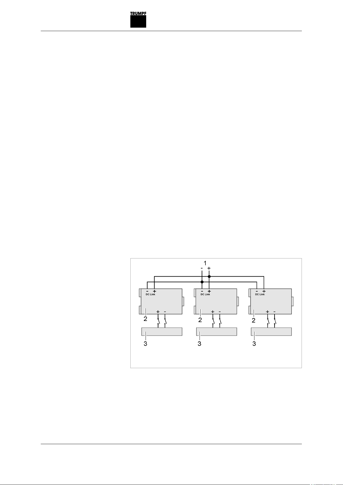
■Up to 3 DC-DC modules can be connected in parallel on the
DC link side (more devices on request) (see "Fig. 2-1",
pg. 2‐3).
■Up to 3 DC-DC modules can be connected in parallel on the
battery side (see "Fig. 2-2", pg. 2‐4).
1 DC link
2 DC-DC module
3 Battery
Parallel operation of DC link side Fig. 2-1
A67-0140-00.BKen-0
01-05
2020-07-01 Function description 2‐3
Operation modes
Configurations
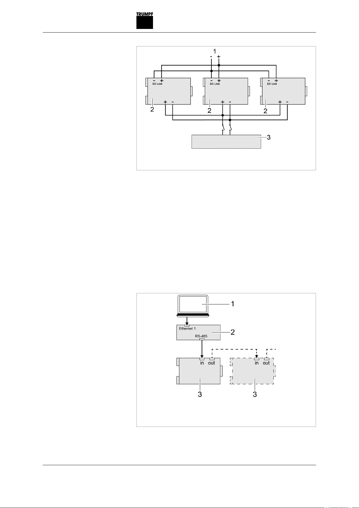
1 DC link
2 DC-DC module
3 Battery
Parallel operation of battery side Fig. 2-2
2.1 Operation
The DC-DC module can be operated via:
■PC with a web browser
■Modbus TCP/UDP
In both cases, the TruConvert System Control must be con-
nected upstream. In the "DC only" configuration, a TruCon-
vert System Control can control up to 16 DC-DC modules (see
"Fig. 2-3", pg. 2‐4).
1 PC with web browser or Mod-
bus master
2 TruConvert System Control
3 TruConvert DC series 1000
Operation with TruConvert System Control Fig. 2-3
2‐4Function description 2020-07-01 A67-0140-00.BKen-0
01-05
Table of contents
Popular Media Converter manuals by other brands

Ltech
Ltech LT-995 manual

Baumer
Baumer MHGP 200 Mounting and operating instructions

Asus
Asus Xonar Essence STU Quick start guides

ABB
ABB ACS150 series Quick installation and start-up guide

Cypress
Cypress CLUX-SDI2VS Operation manual

Cross Technologies
Cross Technologies 2017-0923 370 Series instruction manual


DEVA Broadcast
DEVA Broadcast DB9009-TX Maintenance and operation instruction manual

Linear Technology
Linear Technology DC257 Demo Manual

GRASS VALLEY
GRASS VALLEY ADVCMINI - datasheet

MicroE Systems
MicroE Systems Mercury 1000 Installation manual and reference guide

Danfoss
Danfoss EC-C1200-450 user guide

turck
turck Ri-QR24 operating instructions