Trumpf TruTool N 200 User manual
Operator's manual
English
TruTool N 200 (1A2)


E609EN_01.DOC Contents 3
Contents
1. Safety ..................................................................................4
1.1 General safety information...................................................4
1.2 Specific safety information...................................................4
2. Description .........................................................................6
2.1 Intended use ........................................................................7
2.2 Technical data of the TruTool N 200 ...................................8
3. Setting work .......................................................................9
3.1 Installing the exhaust hose ..................................................9
4. Operation..........................................................................10
4.1 Working with the TruTool N 200 ........................................10
4.2 Changing the cutting direction ...........................................11
4.3 Making inner cutouts..........................................................11
4.4 Nibbling with templates......................................................12
5. Maintenance .....................................................................13
5.1 Replacing the tool ..............................................................14
Disassembling the punch .............................................15
Installing the punch.......................................................15
Replacing the die..........................................................15
5.2 Supplying with power and guaranteeing lubrication ..........16
5.3 Replacing fins ....................................................................17
5.4 Cleaning the strainer..........................................................18
5.5 Changing mufflers..............................................................18
6. Original accessories and wearing parts........................19
7. Disposal............................................................................20
Guarantee
Spare parts list
Addresses

4 Safety E609EN_01.DOC
1. Safety
1.1 General safety information
¾Before starting-up the machine, read the operator's manual
and the safety information (order no. 0373678, red document)
in its entirety and carefully follow the instructions given.
¾Comply with the safety regulations in accordance with
DIN VDE, CEE, AFNOR as well as any other regulations that
apply in the individual countries.
Danger
Risk of fatal injury from electric shock!
¾When working with the machine do not touch any electrical
lines. The machine is not insulated.
Warning
Risk of injury due to improper handling!
¾Always remove the compressed air hose from the machine
prior to maintenance work.
¾Check the compressed air hose, connection coupling, and
machine for damage each time before using the machine.
¾Wear safety glasses, hearing protection, protective gloves
and work shoes when working at the machine.
¾Connect compressed air only when the machine is switched
off.
¾Always lay the compressed air hose away from the back of
the machine.
1.2 Specific safety information
Warning
Risk of injury to hands
¾Do not reach into the processing line with your hand.
¾Use both hands to hold the machine.
Warning
Risk of injury from hot and sharp chips!
Hot chips and sharp chips are emitted from the chip
dumping at high speed.
¾The use of a chip bag is recommended.

E609EN_01.DOC Safety 5
Warning
Risk of injury due to improper handling!
¾Make sure the machine is always in a stable position when
operating it.
¾Never touch the tool while the machine is running.
¾Always move the machine during work away from your body.
¾Do not operate the machine above your head.
Caution
Damage to property due to improper handling!
Machine will be damaged or destroyed.
¾Have servicing and inspections of hand-held compressed air
tools carried out by a qualified technician. Only use original
TRUMPF accessories.
6 Description E609EN_01.DOC
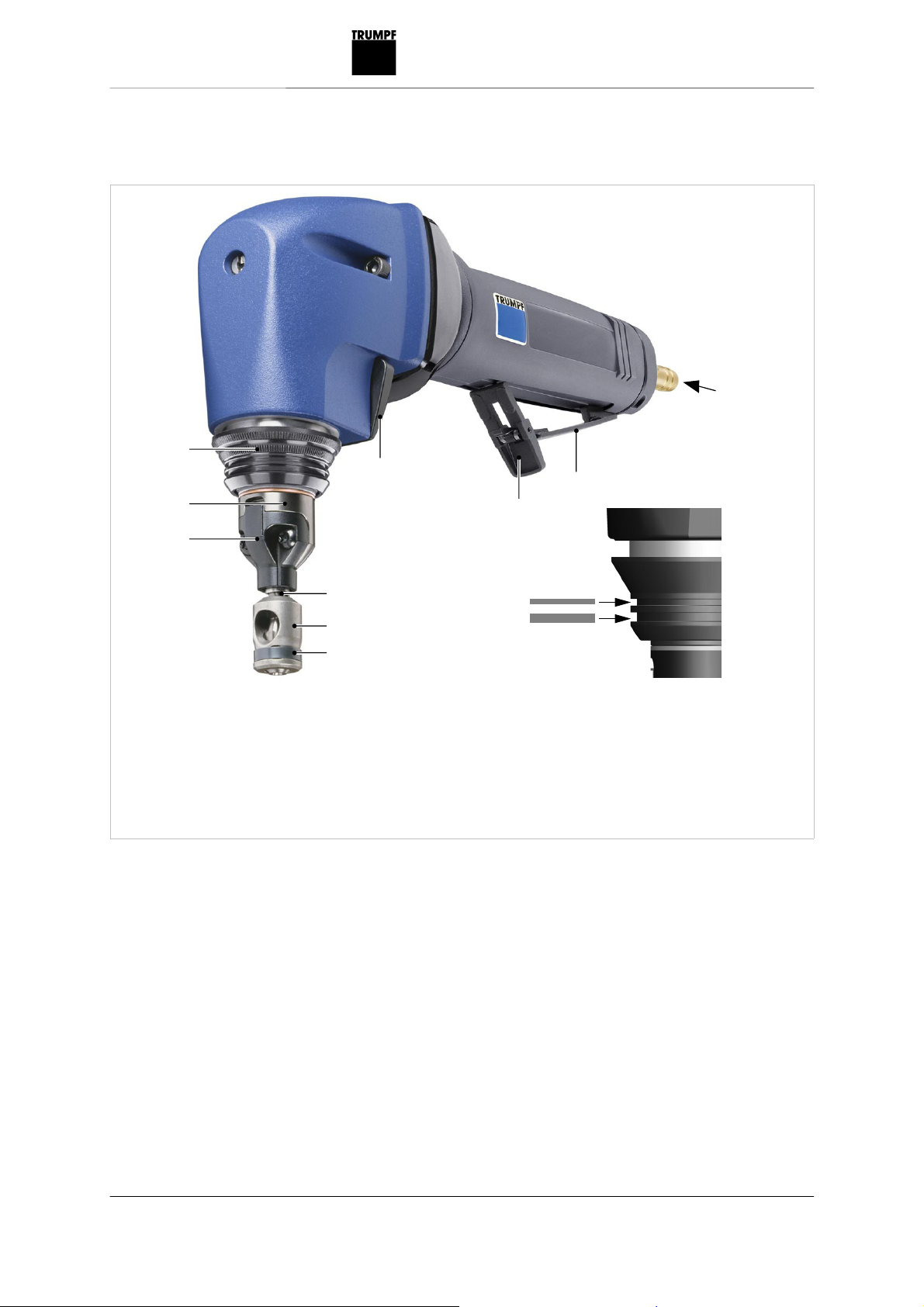
2. Description
1
347
9
A
B
8
2
3
6
5
4
7
1 Index sleeve for direction of tool
2 Die carrier
3 Punch guide
4 Cover ring
5 Die
6 Punch
7 Grip for tool clamp
8 Safety lever
9 Lever
347 Sleeve
A Max. material thickness 1.5 mm
for stainless steel up to 600
N/mm²
B Max. material thickness 2.0 mm
for steel up to 400 N/mm²
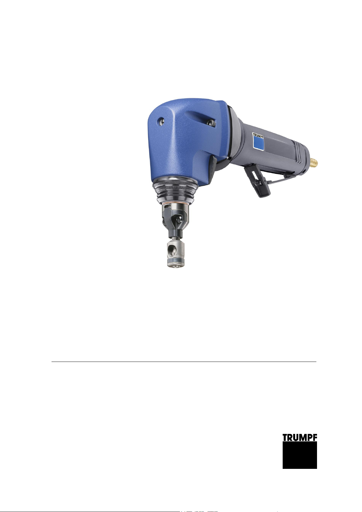
Nibbler TruTool N 200
Fig. 52526

E609EN_01.DOC Description 7
2.1 Intended use
Warning
Risk of injury
¾Only use the machine for the tasks and materials described in
"Intended use".
The TRUMPF Nibbler TruTool N 200 is a hand tool powered by
compressed air used for the following applications:
•Slitting plate-shaped workpieces made of a punchable material
such as steel, aluminum, non-ferrous heavy metals, and
plastic.
•Nibbling straight or curved exterior and interior cutouts.
•Slitting tubes as well as machining sectional sheets.
•Nibbling along scribed lines or templates.
Notes
•The nibbling process produces cutting edges free of
deformations.
•Because of the hollow round punch, the nibbler can be rotated
at any position such that processing can continue mm any
direction.

8 Description E609EN_01.DOC
2.2 Technical data of the TruTool N 200
Other countries USA
Value Value
Max. material thickness:
Steel 400 N/mm²
Steel 600 N/mm²
Steel 800 N/mm²
Aluminum 250 N/mm²
2.0 mm
1.5 mm
1.0 mm
2.5 mm
0.079 in
0.06 in
0.039 in
0.1 in
Working speed 1.3 m/min 4.2 ft/min
Nominal power consumption 600 W 600 W
Idle stroke rate 1600/min 1600/min
Stroke rate with nominal load 1300/min 1300/min
Weight 1.9 kg 4.2 lbs
Start hole diameter 16 mm 0.63 in
Smallest radius with curved cuts 4 mm 0.16 in
Max. operating pressure
(flow pressure)
6.2 bar 90 psi
Air consumption at 6 bar 0.8 m³/min 28.3 cubic ft/min
Connecting thread 1/4" 1/4"
Inside diameter of the compressed
air hose
10 mm 0.4 in (3/8")
Technical data
Vibration Specifications in accordance with
EN 12096
Measured values in accordance
with EN ISO 8662-10
Vibration value at the handle a 13.3 m/s²
Uncertainty K 4.6 m/s²
Measured values were measured while cutting sheet steel
400 N/mm² with max. material thickness.
Table 1
Table 2
E609EN_01.DOC Setting work 9
Noise emissions Designations in accordance with
EN ISO 4871
Measured values in accordance
with EN ISO 15744
A-rated sound level LWA 93 dB
A-rated acoustic power level at the
work place LPA
82 dB
The noise emission values given are the sum
of the measured values and the corresponding uncertainties. They
represent an upper value limit which can emerge during
measurements.
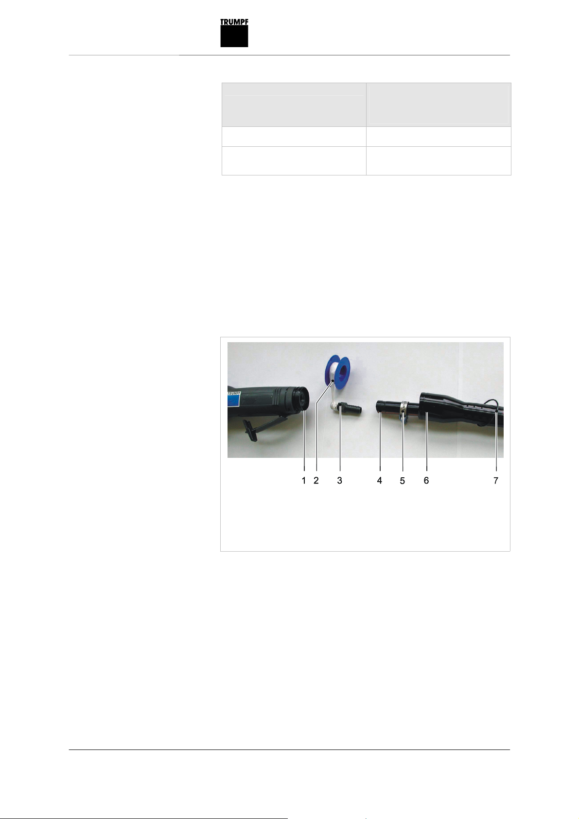
3. Setting work
3.1 Installing the exhaust hose
The exhaust hose reduces noise emissions and guides the
exhaust air away from the operator.
1 Adapter
2 Teflon tape
3 Sleeve
4 Compressed air hose
5 Hose clip
6 Exhaust hose
7 Spring ring
Exhaust hose
1. Put the exhaust hose (6) and the hose clip
(5) over the compressed air hose (4).
2. Undo the spring ring (7) and screw the adapter (1) onto the
motor.
3. Wind Teflon tape (2) around the sleeve (3).
4. Firmly screw in the sleeve (3) in the motor.
5. Push the compressed air hose (4) on to the sleeve (3).
6. Position the hose clip (5) and tighten.
7. Push the exhaust hose (6) on to the adapter (1).
8. Secure the exhaust hose (6) using the spring ring (7).
Table 3
Fig. 52422

10 Operation E609EN_01.DOC
4. Operation
4.1 Working with the TruTool N 200
Warning
Risk of injury due to improper handling!
¾Make sure the machine is always in a stable position when
operating it.
¾Never touch the tool while the machine is running.
¾Always move the machine during work away from your body.
¾Do not operate the machine above your head.
1. Turn the safety lever (8).
2. Press the lever (9) against the motor housing.
Note
The cutting result is improved and the service life of the punch
increased if the cutting track is coated with oil before machining the
workpiece.
Material Oil
Steel Punching and nibbling oil ( 0.5 l, order no. 103387)
Aluminum Wisura oil (1 l, order no. 125874)
1. Do not move the machine towards the workpiece until full
speed has been reached.
2. Machine the material.
–Machine the desired cutting line
3. In the event that the cutting track ends in the sheet, pull the
still-running machine a few millimeters back towards where the
cutting track has already been cut open.
4. Switch the machine off.
¾Release the lever.
The lever springs back to initial position, the compressed air is
interrupted.
Switching on the
TruTool N 200
Table 4
Working with the
TruTool N 200
Switching off the
TruTool N 200
E609EN_01.DOC Operation 11
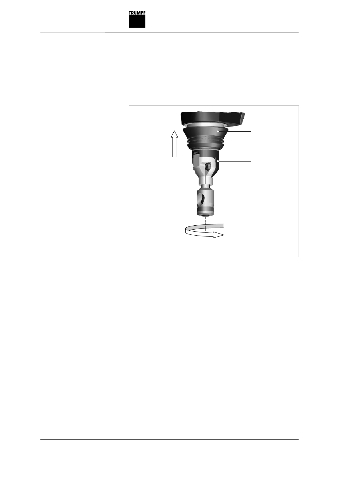
4.2 Changing the cutting direction
The direction of the cut can be rotated to the right or the left in 5°
increments as needed.
•For right-handed/left-handed operation.
•Machining sectional sheets.
2
1
1 Sleeve 2 Tool
1. Push the sleeve (1) up until it stops.
2. Turn the tool (2) to the desired direction.
3. Release the sleeve (1) and turn the tool (2) slightly such that it
locks into the next index position.
4.3 Making inner cutouts
¾Make a start hole at least 16 mm in diameter.
Fig. 25666
12 Operation E609EN_01.DOC
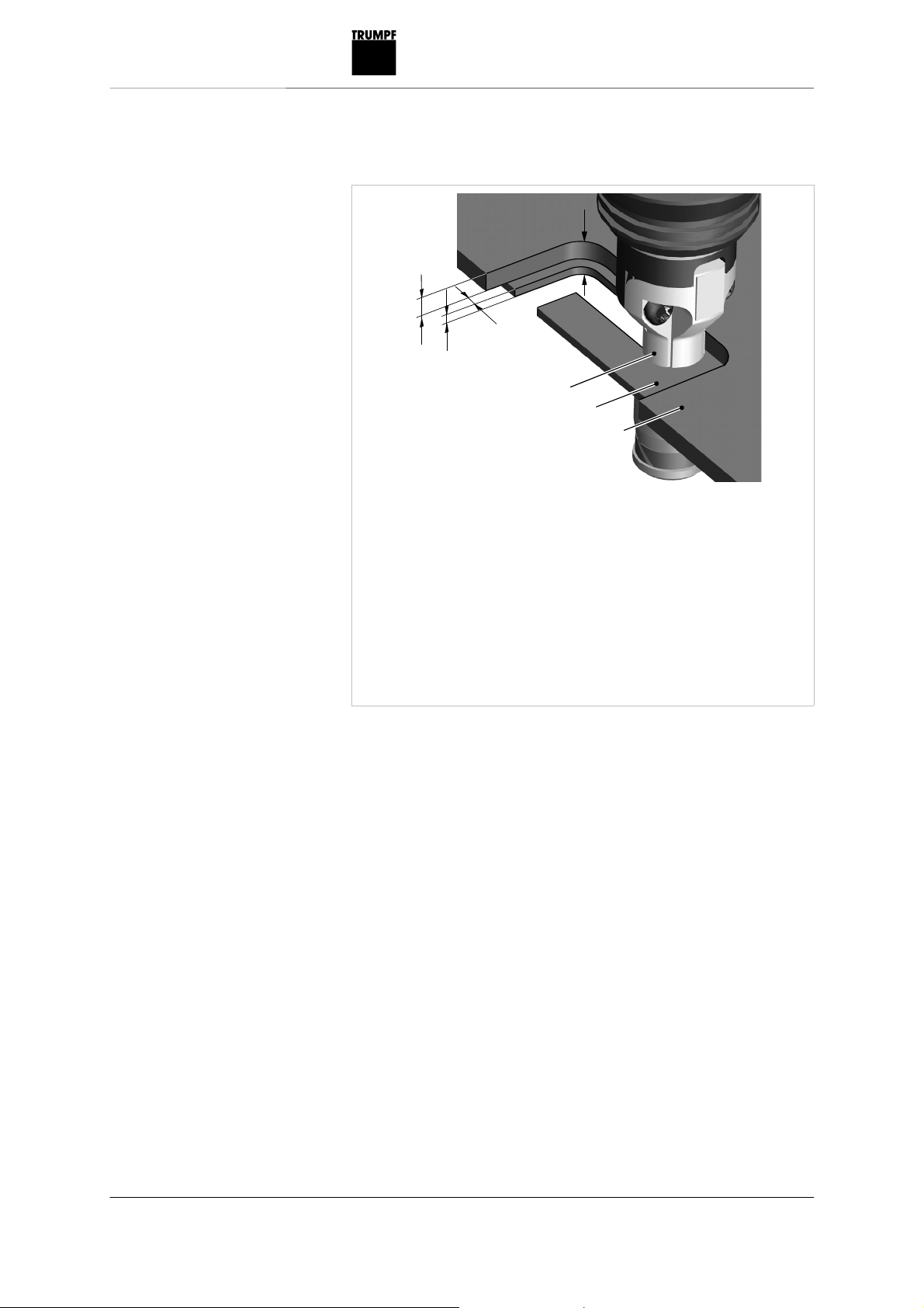
4.4 Nibbling with templates
h1
a
R1
R2
1
2
3
h2
1 Punch guide, outside diameter
13 mm
2 Workpiece
3 Template
a Clearance of the contour of the
template to the contour of the
workpiece to be nibbled out:
2.5 mm
h1 Thickness of the template
h2 Thickness of the workpiece
h1+h2 Total thickness of template and
workpiece: 5-6.5 mm
R1Minimum radius in the
template:6.5 mm
R2 Minimum radius in the work-
piece: 4 mm (= punch-radius)
Fig. 25828
E609EN_01.DOC Maintenance 13
5. Maintenance
Warning
Risk of injury due to uncontrolled machine movements.
¾Remove the compressed air hose when changing tools and
before performing any maintenance work on the machine.
Caution
Damage to property caused by blunt tools!
Machine overload.
¾Check the cutting edge of the cutting tool hourly for wear. A
sharp punch provides good cutting performance and is easier
on the machine. Replace punches promptly.
Warning
Risk of injury due to repair work not being carried out
properly!
Machine does not work properly.
¾Repair work may only be carried out by a qualified technician.
Maintenance point Procedure and interval Recommended lubricant Lubricant
order no.
Punch guide With each tool change Lubricating grease "G1" 344969
Gearbox and gear head After 300 operating hours, arrange
for a qualified technician to
relubricate or to replace the
lubricating grease
Lubricating grease "G1" 139440
Punch Replace as necessary - -
Die Replace as necessary - -
Filter, oil mist lubrication
device
Maintain daily in accordance with
the manufacturer's specifications
(see "Supplying with power and
guaranteeing lubrication", p. 16)
- -
Strainer Clean every 10 operating hours
and when there has been a
decline in performance (see
"Cleaning the strainer", p. 18).
- -
Maintenance points and maintenance intervals
Table 5
14 Maintenance E609EN_01.DOC
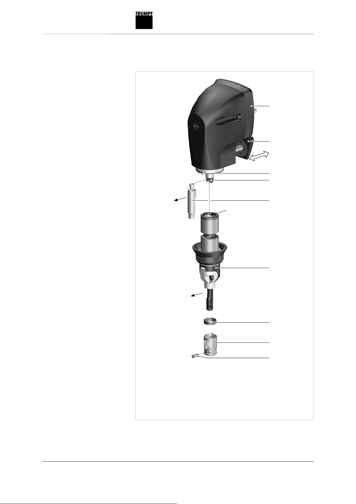
5.1 Replacing the tool
1
2
3
4
5
6
8
9
7
S
S
F
1 Housing
2 Grip for tool clamp
3 Index pins
4 Ram with punch adapter
5 Punch
6 Tool
7 Cover ring
8 Die
9 Cylindrical pin
F Lubricating grease "G1"
S Direction of cutting
¾If the punch or die becomes blunt, change the tool.
Fig. 25655

E609EN_01.DOC Maintenance 15
Disassembling the punch
1. Pull handle (2) back.
2. Pull tool (6) out of the housing (1).
3. Remove punch (5).
Installing the punch
1. Lightly lubricate the punch (5) and the boring in the tool (6) with
lubricating grease "G1".
2. Hang the punch in the groove of the punch adapter.
3. Align the cutting direction towards the front.
4. Insert tool (6) into the housing (1) with cutting direction facing
towards the front.
5. Slide handle (2) back; the tool (6) is kept in the housing.
Replacing the die
1. Push cover ring (7) upward out of slot.
2. Push out cylindrical pin (9) using a drift punch.
3. Pull off die (8) from the carrier pin and replace it with a
new die.
4. Set die on the carrier pin.
5. Mount cylindrical pin.
6. Slide the cover ring in the nut downwards.
16 Maintenance E609EN_01.DOC
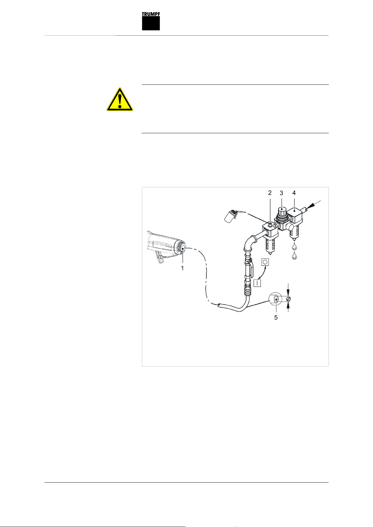
5.2 Supplying with power and
guaranteeing lubrication
Caution
Damage to property due to improper handling!
Failure of the compressed air motor.
¾Do not exceed the maximum operating pressure.
¾Regularly lubricate the compressed air motor. Install an oil
mist lubrication device into the compressed air line.
Condition
•The pressure regulating valve and the connecting threads are
laid out correctly (see "Technical data", section 2.2, p. 8).
1 Connecting thread 1/4"
2 Oil mist lubrication device
3 Pressure regulating valve
4 Filter and water separator
5 Inside diameter of the
compressed air hose min.
10 mm or 3/8"
Compressed air supply.
1. Install the filter and water separator (4).
2. Drain/check the water separator daily.
Note
To ensure a supply of compressed air the tube cross-sections in
the entire line system must be twice to three times the size of the
inside diameter of the compressed air hose.
Supplying compressed air
Fig. 52385

E609EN_01.DOC Maintenance 17
¾Hold a piece of paper in front of the exhaust air vent in the
motor housing when the machine is running.
The oil supply is sufficient when oil spots appear.
When there is no oil mist lubrication device available:
¾Fill the air inlet bore hole with 0.5-1 ccm of oil every two hours.
Recommended lubricant:
•BP Energol RD 80 (-15° to +10 °C/+5° to +50 °F).
•BP Energol RD-E80 (+10° to +30 °C/+50° to +86 °F).
•Shell Tellus Oil 15 (-15° to +10 °C/+5° to +50 °F).
•Torculla 33 (+10° to +30 °C/+50° to +86 °F).
Note
Secure the compressed air hose against undesired movements
using a compressed air safety device.
5.3 Replacing fins
Worn fins decrease machine performance.
¾Have the fin set checked and replaced as needed by a
qualified technician.
Note
Only use original replacement parts and observe the information
on the rating plate.
Checking the oil supply

18 Maintenance E609EN_01.DOC
5.4 Cleaning the strainer
Dirty strainers decrease machine performance.
1
1
2
3
1 Muffler
2 Housing ring
3 Air inlet with strainer
Air inlet
1. Remove the air inlet with strainer.
2. Clean the strainer or replace the complete air inlet.
3. Reinstall the air inlet.
5.5 Changing mufflers
Change the mufflers as needed (see Fig. 52402, p. 18).
1. Remove the air inlet (3).
2. Pull off the housing ring (2).
3. Replace the mufflers (1).
4. Reinstall the housing ring and the air inlet.
Fig. 52402

E609EN_01.DOC Original accessories and wearing parts 19
6. Original accessories and wearing parts
Designation Supplied
original
accessories
Wearing parts Options Order no.
Punch + + 944506
Die + + 980335
Lubricating grease "G1"
(25 g/0.055 lbs)
+ 344969
Case + 1445078
Sleeve + 0376078
Fin set (4 pieces) + 1440002
Operator's manual + 1440930
Safety information (red document) + 0373678
Tool TruTool PN 200 (1A2) + 1418628
Torx Spanner Tx20 + 0359907
Chip bag + 088622
Replacement part set (2 punches,
1 die, 1 pin, 1 cover)
+ 961961
Punching and nibbling oil for steel (0.5
l)
+ 103387
Punching and nibbling oil for
aluminum (1 l)
+ 125874
To ensure the correct and fast delivery of original parts and
wearing parts:
1. Specify the order number.
2. Enter further order information:
–Voltage data.
–Quantity
–Machine type.
3. Provide complete shipping information:
–Correct address.
–Desired delivery type (e.g. air mail, courier, express mail,
ordinary freight, parcel post).
4. Send the order to your TRUMPF representative. Refer to the
address list at the end of the document for TRUMPF service
addresses.
Table 6
Ordering wearing parts

20 Disposal E609EN_01.DOC
7. Disposal
To dispose of the machine, completely disassemble it, degrease it
and send it, according to the different types of material, for
recycling.
Other manuals for TruTool N 200
2
Table of contents
Other Trumpf Tools manuals


 User manual")

Popular Tools manuals by other brands


Rose electronics
Rose electronics ALL2GETHER owner's manual

Allway
Allway DSRK-B6 Product guide

Victaulic
Victaulic RG2910 Operating and maintenance instruction manual

gerardi
gerardi MULTIFLEX Instructions for the use and maintenance

Westfalia
Westfalia 85 96 83 instruction manual

DICSA
DICSA CBOXSMART instruction manual