Truper ROU-MN User manual

ROU-MN
Manual
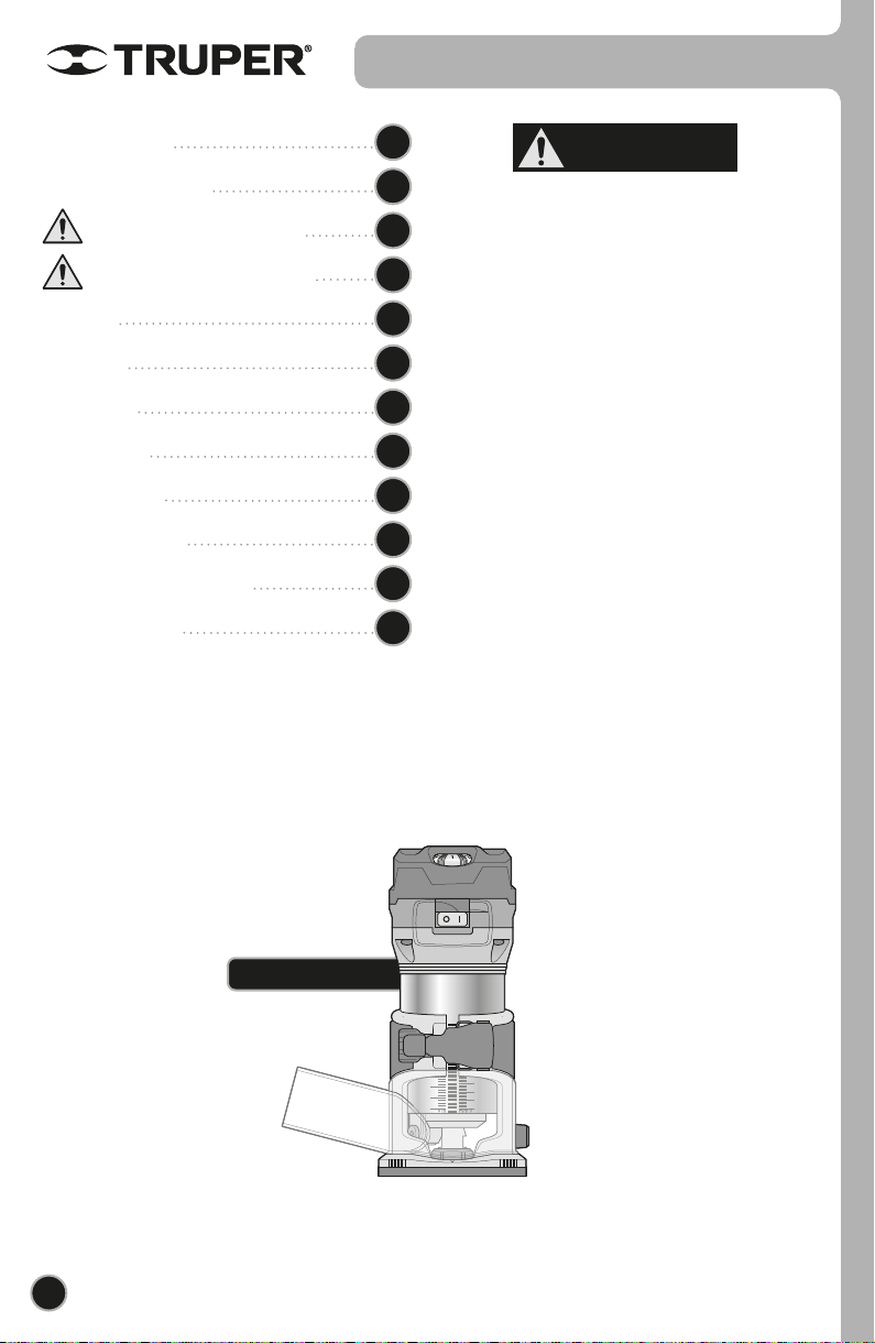
Compact Router
ModelCode
ROU-MN
Applies for:
102315
Power
0.95 HP
ENGLISH
ESPAÑOL
CAUTION Read this manual thoroughly
before using the tool.
2
Technical data
Power requirements
General power tool safety warnings
Safety warnings for the use of routers
Parts
Set up
Start up
Operation
Maintenance
Troubleshooting
Authorized service centers
Warranty policy
3
3
4
5
6
7
9
10
14
14
15
16
ROU-MN
ENGLISH
CAUTION
Contents
Keep this manual for future references.
The illustrations in this manual are for reference
only. They might be different from the real tool.
To gain the best performance of
the tool, prolong the duty life,
make the Warranty valid if
necessary, and to avoid hazards
of fatal injuries please read and
understand this Manual before
using the tool.

Power requirements
3
ROU-MN
102315
Class II
60 Hz
Compact Router
18 AWG x 2C with insulation temperature of 221 °F
5.6 A 0.95 HP
Code
Description
Voltage Frequency
PowerCurrent
10000 RPM - 30000 RPM
For drills with 1/4” shanks
Speed
Collar clamps
3 1/2” 1 1/8”
Base diameter
1 3/8”
Maximum cutting depth:
Maximum drill diameter
Conductors
Insulation IP 20
IP Grade
El cable de alimentación tiene sujeta-cables tipo: Y
La clase de construcción de la herramienta es: Aislamiento reforzado.
La clase de aislamiento térmico de los devanados del motor: Clase E
127 V
Technical Data
ENGLISH
Tools with double insulation and reinforced insulation are built with a
polarized plug (one prong is wider than the other) This plug fits in any polarized outlet
and can only be connected one way. If the plug does not fit completely into the outlet,
reverse the plug. If it is not fitting, call a qualified electrician or install a polarized outlet.
Do not alter the plug in any way. Double insulation eliminates the need of a three-prong
grounded power plug or a grounded electric system.
When using an extension cable, make it has sufficient gauge to
carry the current your tool will draw. A lower gauge cable will cause voltage drop in the line, resulting in power loss and
the motor will overheat. The following table shows the right size to use depending on cable’s length and the ampere
capability shown in the tool’s nameplate. When in doubt use the next higher gauge.
WARNING
WARNING
From 0 and up to 10 A
From 10 and up to 13 A
From 13 and up to 15 A
From 15 and up to 20 A
18 AWG
16 AWG
14 AWG
8 AWG
16 AWG
14 AWG
12 AWG
6 AWG
3 (one grounded)
From 6 ft to 49 ft | Higher than 49 ft
Ampere
Capacity Number of
Conductors Extension Gauge
When using power tools outdoors use grounded extension cable labeled “Outdoors
Use”. These extension cables are specially manufactured for outdoors use and reduce the risk of electric shock.
WARNING
WARNING
WARNING Avoid the risk of electric shock or severe injury. When the power cable gets damaged
it should only be replaced by the manufacturer or at a Authorized Service Center.
The build quality of the electric insulation is altered if spills or liquid gets into the tool while in use.
Do not expose to rain, liquids and/or dampness.
Before gaining access to the terminals all power sources should be disconnected.
*It is safe to use only if the extensions have a built-in artifact for over current protection.
AWG = American Wire Gauge. Reference: NMX-J-195-ANCE

4ENGLISH
This tool is in compliance with
the Official Mexican Standard
(NOM - Norma Oficial Mexicana).
Work area
Keep your work area clean, and well lit.
Cluttered and dark areas may cause accidents.
Never use the tool in explosive atmospheres, such as in the
presence of flammable liquids, gases or dust.
Sparks generated by power tools may ignite the flammable material.
Keep children and bystanders at a safe distance while operating
the tool.
Distractions may cause loosing control.
Electrical Safety
The tool plug must match the power outlet. Never modify
the plug in any way. Do not use any adapter plugs with
grounded power tools.
Modified plugs and different power outlets increase the risk of electric shock.
Avoid body contact with grounded surfaces, such as pipes,
radiators, electric ranges and refrigerators.
The risk of electric shock increases if your body is grounded.
Do not expose the tool to rain or wet conditions.
Water entering into the tool increases the risk of electric shock.
Do not force the cord. Never use the cord to carry, lift or unplug
the tool. Keep the cord away from heat, oil, sharp edges or
moving parts.
Damaged or entangled cords increase the risk of electric shock.
When operating a tool outdoors, use an extension cord suitable
for outdoor use.
Using an adequate outdoor extension cord reduces the risk of electric shock.
If operating the tool in a damp location cannot be avoided, use
a ground fault circuit interrupter (GFCI) protected supply.
Using a GFCI reduces the risk of electric shock.
Personal safety
Stay alert, watch what you are doing and use common sense
when operating a tool. Do not use a power tool while you are
tired or under the influence of drugs, alcohol or medication.
A moment of distraction while operating the tool may result in personal injury.
Use personal protective equipment. Always wear eye
protection.
Protective equipment such as safety glasses, anti-dust mask, non-skid shoes,
hard hats and hearing protection used in the right conditions significantly
reduce personal injury.
Prevent unintentional starting up. Ensure the switch is in the
“OFF” position before connecting into the power source and /
or battery as well as when carrying the tool.
Transporting power tools with the finger on the switch or connecting power
tools with the switch in the “ON” position may cause accidents.
Remove any wrench or vice before turning the power tool on.
Wrenches or vices left attached to rotating parts of the tool may result in personal
injury.
Do not overreach. Keep proper footing and balance at all times.
This enables a better control on the tool during unexpected situations.
Dress properly. Do not wear loose clothing or jewelry. Keep
hair, clothes and gloves away from the moving parts.
Loose clothes or long hair may get caught in moving parts.
If you have dust extraction and recollection devices connected
onto the tool, inspect their connections and use them correctly.
Using these devices reduce dust-related risks.
Power Tools Use and Care
Do not force the tool. Use the adequate tool for your
application.
The correct tool delivers a better and safer job at the rate for which it was designed.
Do not use the tool if the switch is not working properly.
Any power tool that cannot be turned ON or OFF is dangerous and should be
repaired before operating.
Disconnect the tool from the power source and / or battery
before making any adjustments, changing accessories or
storing.
These measures reduce the risk of accidentally starting the tool.
Store tools out of the reach of children. Do not allow persons
that are not familiar with the tool or its instructions to
operate the tool.
Power tools are dangerous in the hands of untrained users.
Service the tool. Check the mobile parts are not misaligned or
stuck. There should not be broken parts or other conditions that
may affect its operation. Repair any damage before using the
tool.
Most accidents are caused due to poor maintenance to the tools.
Keep the cutting accessories sharp and clean.
Cutting accessories in good working conditions are less likely to bind and are
easier to control.
Use the tool, components and accessories in accordance with
these instructions and the projected way to use it for the type of
tool when in adequate working conditions.
Using the tool for applications different from those it was designed for, could
result in a hazardous situation.
Service
Repair the tool in a Authorized Service Center
using only identical spare parts.
This will ensure that the safety of the power tool is maintained.
General power tool
safety warnings
WARNING! Read carefully all safety warnings and instruction listed below. Failure to comply with any of
these warnings may result in electric shock, fire and / or severe damage. Save all warnings and instructions for
future references.

5
Safety warnings for
the use of routers
• Keep hands away from cutting area and
cutting bit. When operating the tool, hold it firmly by the
non-slip handle to avoid accidental injury and prevent
loss of control.
• Accidental contact with a rotating
cutting bit can result in serious personal injury.
• NEVER hold the workpiece with your
hands or on one leg. Hold the workpiece properly to
avoid body contact with the cutting bit, binding of the bit,
or loss of control of the tool or workpiece.
• Do not attempt to remove scrap
material when the cutting bit is rotating.
• Never put your hand under the
workpiece while the tool is running.
• Before each use check all parts for
proper operation, if something is not working give service
before operating the tool.
• Before transporting the tool remove the
cutting bit.
• Operating the tool while holding it by its
insulated parts avoids shocks to the operator in case the
blade contacts hidden electrical wiring.
• Before servicing, removing or
installing bits, parallel guide or dust extractor adapter, you
must disconnect the tool from the power supply.
• ALWAYS keep the power cord away from the cutting
area. The power cord should NEVER hang over the
workpiece when cutting.
• Always wear safety glasses with side shields. If dust is
produced also wear a dust mask.
Dusts from cutting certain materials contain chemicals
known to cause health hazards. To reduce exposure to
these chemicals, work in well-ventilated areas, and use
appropriate safety equipment, such as dust masks
specifically designed to filter out microscopic particles.
Toxic materials
• RISK OF KICKBACK. Kickback refers
to the sudden, forceful movement of the tool away from
the workpiece that can cause the operator to lose control
or even cause injury. It is usually caused when the cutting
bit gets stuck in the workpiece or by poor operation. To
avoid this, the following precautions should be taken:
• Use cutting bits in good condition and
make sure they are properly installed. Poorly installed,
damaged, dull or worn bits tend to get stuck in the
material causing kickback.
• When operating the router, hold the
router firmly by the non-slip handle. Keep your body well
balanced and in a stable position with both feet on the
floor to resist the force of a possible kickback.
• To make a cut, wait for the drill bit to
reach full speed before starting to cut. Do not start the
tool with the drill bit resting on the workpiece, it may
cause kickback.
• To restart work within a cut, center the drill bit in the cut.
• If cutting is interrupted during router
operation, turn the switch off and hold the tool inside the
workpiece until the motor comes to a complete stop. Do
not attempt to remove the bit while the motor is still
running, it may cause kickback.
• To minimize the risk of the bit binding
and causing kickback, remove all nails before cutting a piece
of wood. Wet, warped or pressure-treated wood requires
special attention during cutting. The gum and resin in the
wood that hardens on the cutting bits slows the router. Use
gum and resin remover, hot water or kerosene to remove
these buildups. DO NOT use gasoline.
• Before starting any cut, the depth of
cut adjustment knobs must be tightened and secured. If
they move during the cut, kickback may result.
• Excessive depth cuts and/or the use of
large diameter bits increase the load on the unit and the
possibility of kickback. Make several passes with the
router at progressive depths when the job requires
removal of a lot of material or when using large diameter
bits.
ENGLISH
CAUTION
CAUTION
CAUTION
CAUTION
CAUTION
CAUTION
CAUTION
CAUTION
CAUTION
DANGER
DANGER
DANGER
WARNING
WARNING
WARNING
WARNING
WARNING

0 in mm 0
1
2
6
Parts
Fine height
adjustment knob
Splinter
guard
Parallel and circle
cutting guide
Edge
guide
Hex
keys
Copying guide
1/2” and 7/8”
wrenches
Carbon
cover
Handle with
anti-skid
cover
Graduated
cylinder
Switch
Knob for securing
the splinter guard Knob to secure accessories
(cutting guides)
Power
cord
Power cord
protector
Base
guard
Base
Shaft
lock
Locking lever
Vacuum
port Collar
Speed
control
6ENGLISH

7
Set up
• Before installing or removing a drill bit,
turn off and disconnect the router from the power source.
You can perform drill bit installation and demounting in two
ways:
1. By removing the cylinder.
• Remove the cylinder (A) from the fixed base as described
in the previous section and rest the motor head on a flat
surface with the cylinder pointing up.
• Depress the shaft lock (G) to prevent the shaft from
rotating.
• Without releasing the shaft lock, loosen the collar nut (H)
with the 7/8” wrench ( I).
• Place the drill bit ( J) in the collet, the shank must enter at
least 19/32" to ensure that the drill bit does not accidentally
come out.
• Tighten the collet nut firmly with the wrench to secure the
drill bit.
• Release the spindle lock (G) and make sure that the drill
bit is securely in place.
• To remove the drill bit, depress the spindle lock and
loosen the collet nut with the wrench provided.
2. Without removing the cylinder.
• Remove the drill bit as explained in the previous section.
• Use the 1/2” wrench (K) to secure the shaft to prevent it
from turning.
• Hold the collar (H) with the 7/8” wrench ( I) and turn the
nut counterclockwise.
• Place the 7/8” wrench on the collar and the 1/2” wrench
on the motor shaft.
• Hold the 1/2” wrench and loosen with the 7/8” wrench.
• Place the drill bit in the collet the shank must go in at least
19/32" to ensure that the drill bit does not accidentally come out.
• Replace the 1/2” wrench and tighten firmly with the 7/8” wrench.
• To remove the bit, follow the reverse of the installation procedure.
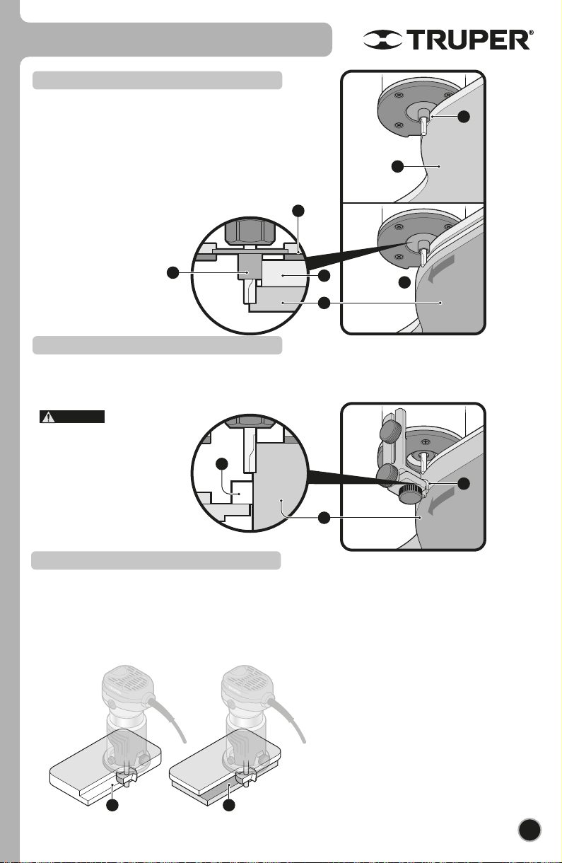
Drill bit installation or disassembly
• The router motor is housed in the vertical cylinder (A)
which raises or lowers inside the fixed base (B) to adjust
the drill bit to the proper height for the work to be
performed.
• Before installing a drill bit or changing
the collet or clamp, the cylinder must be removed from
the fixed base.
• Before disassembling or assembling
the cylinder, turn off and disconnect the router from the
power supply.
• To remove the cylinder, release the lever (C) from the
fixed base clamp.
• Lift the motor head (D) until the cylinder is removed
from the fixed base.
• To reassemble the cylinder, make sure to align the
toothed groove (E) with the base sprocket (F).
• Insert the cylinder into the fixed base.
• Push the lever (C) to close the clamp.
Disassembly and assembly of the cylinder
J
C
A
E
A
D
F
K
I
I
G
H
H
B
Loosen
Tighten
ENGLISH
CAUTION
CAUTION
CAUTION

E
G
F
D
BA
8
Set up
• Slide the parallel guide slot (C) into the screw on the
back of the router and secure it in place by tightening
the knob (D).
• Depending on the work to be performed, the router
accepts different types of auxiliary guides: parallel
guide, edge guide or copying guide.
Parallel guide installation
• Slide the edge guide slot (E) into the screw on the
back of the router and secure it in place by tightening
the knob (D).
Edge guide installation
• Attach the chip cover (also vacuum port) (A) to the
front of the router base.
• To secure it in place, tighten the knob (B).
• The cover must be mounted and
secured before operating the router.
Splinter shield assembly
• Loosen the screws and remove the base protector (F).
• Put the copying guide (G) on the base and replace the
base protector. Then fasten the base protector by
tightening the screws.
Assembly of the copying guide
C
D
ENGLISH
CAUTION

1
2
1
2
6
• Before adjusting the height of cut, turn
off and disconnect the router from the power source.
• Rest the router base on a flat, level surface with the front
of the router facing you.
• Open the lever (F) on the stationary base.
• With the cutter bit already installed, push down on the
cylinder until the bit is very close to the surface on which
the outer is resting (1).
• Turn the fine height adjustment knob (G) until the drill
bit barely touches the surface on which the router is
resting. This point should be considered as 0 penetration.
• Place the router on two pieces of scrap work that are
level and position it so that the drill bit can be lowered
underneath the base of the router (2).
• Rotate the fine height adjustment knob (G) to lower the
drill bit to the desired depth of cut. Turn in the opposite
direction to raise the bit.
• Once you determine the depth of cut, close the lever (F)
on the fixed base.
Cutting height adjustment
9
Start up
F
A
G
• Connect the router to the power source.
• Use the switch (A) to turn the router motor on or off. To
turn on press the switch to the "O" mark, to turn off press
the switch to the "I" mark.
• When turning the motor on, wait until
the drill bit reaches full speed to make contact with the
workpiece.
• When turning the motor off, wait for
the drill bit to come to a complete stop before removing
the drill bit from the workpiece.
• The motor is configured to minimize torque by limiting
its speed during start-up, which increases its life.
• The motor features electronic feedback control that
maintains constant speed under load to provide proper
control and ensure a smooth finish.
Start-up and operation control
ENGLISH
CAUTION
CAUTION
CAUTION

1
2
6
• It is important to perform test cuts on scrap material
before making the cut on the final material. Test cuts allow
the operator to rehearse the cut for speed and depth
adjustments, as well as to get a feel for material response,
cutting direction, and optimal router setup.
• Rest the base of the router on the workpiece before
turning it on. Make sure the bit is not in
contact with the workpiece until you have control of the
router by firmly gripping the non-slip handle (A) and the
motor has reached the maximum speed set for the job.
• Guide the router at a constant speed through the work
piece without exerting too much pressure on the bit,
allowing sufficient time for the bit to cut the material.
C
A
B
Operation
10
• When cutting along an edge, be sure to
guide the bit in the same direction as the direction of
rotation of the bit (B). Otherwise, the router may be
triggered unexpectedly and also produce faulty cuts.
Cutting direction
• With the speed control (C) it is possible to determine the speed of the router.
• The control can be adjusted from 1 (lowest speed) to 6 (highest speed).
• The speed can be adjusted with the motor running; however, do not change the speed when the drill
bit is in contact with the workpiece, otherwise loss of control due to sudden vibration may occur.
• This allows the ideal speed to be chosen for optimum processing of the material, i.e., the speed can be adjusted
correctly to match the material and diameter of the cutter. Refer to the table for the relationship between the numerical
settings of the rotary control and the approximate tool speed.
Speed control
Number RPM
1
2
3
4
5
6
10000 RPM
12 000 RPM
17 000 RPM
22 000 RPM
27 000 RPM
30 000 RPM
ENGLISH
CAUTION
CAUTION
CAUTION

E
D
A B C
Operation
11
Parallel guide
• It is not advisable to make deep single-cut cuts. Small diameter bits break easily due to excessive load
and torque; while larger bits produce coarse cuts and are difficult to guide and control. To make a deep cut, make
successive cuts by increasing the depth of the bit up to 1/8” per pass until the desired depth is reached.
Cutting depth
• Install the parallel guide (D) on the router base (page 8),
and rest it on the edge of the workpiece to make straight
cuts.
• If the distance between the cut and the edge of the
workpiece is greater than the opening of the parallel
guide, or if the edge of the workpiece is not straight, use at
least two clamps to hold a straight piece of wood (E) as a
guide. Make the cut by resting the side of the router base
against the piece of wood.
• The speed at which the bit is pushed with the router determines the finish of the cut and depends on several factors:
hardness and moisture content of the workpiece, depth of cut and bit diameter. Usually, shallow cuts in soft woods can be
made with fast movements, while deep cuts in hard woods are made more slowly. To determine the ideal speed, tests on
scrap material are essential. Too fast cutting movements (A) cause the bit to take out very large chunks of material, as well
as overloading the motor. Proper cutting motions (B) cause the bit to take small bites and clean cuts. Too slow cutting
movements (C) generate too much friction in the material, resulting in scratches that expose the material fibers and cause
a scorched cut.
Thrust speed
Parallel
guide
ENGLISH
CAUTION

F
12
Operation
Circle cutting guide
• The parallel guide can be configured to cut circles of different
size ranges.
• The radius of the circle is the distance from the anchor (A) of
the guide to the center of the drill bit.
• To cut circles from 2-1/2” to 4-3/4“ radius, place the wing nut
in the hole closest to the router (B).
• To cut circles from 4-3/4” to 8-11/16“ radius, place the wing
nut in the hole farthest from the router (C).
• This guide cannot cut circles with radii from 6-3/4”
to 7-5/16”.
Circle cutting
guide
NOTE
ENGLISH
• Use a template (A) between the router base (B) and the
workpiece (C).
• Rest the copying guide bushing (D) on the edge of the
template.
• Make the cut without separating the bushing around the
perimeter of the template (E).
Copying guide
• Rest the edge guide roller (F) on the edge of the
workpiece (G).
• Make the cut without separating the roller around the
perimeter of the workpiece.
• Before cutting,
test a scrap piece to determine the
position of the roller. Tighten the
knobs before cutting.
Edge guide
• Drill bits with built-in stops are ideal for working edges.
The workpiece itself can serve as a guide when its
thickness is greater than the height of the drill bit (I). If the
thickness of the work piece is less than the height of the
drill bit, use a guide (K) to make the cut.
A
B
AE
C
G
D
F
D
F
I K
Operation
13
Drill bits with guide stop
ENGLISH
CAUTION
Carbon cover
• Ensure that the machine's ventilation slots are kept free of sawdust/chips, etc.
• Keep the guides clean and lubricated with a light multi-purpose oil.
• Tool repair service should always be performed by a Authorized Service Center. If machine repair
services are performed by personnel not authorized by , the product warranty will be invalidated.
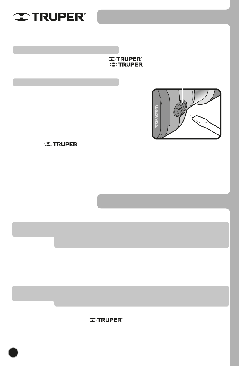
Carbon brush replacement
Repair service
• It is necessary to replace worn out carbon brushes (burnt, broken or less than
5 mm long) with new carbon brushes.
• When replacing the carbon brushes, always replace both carbon brushes.
• Use a screwdriver to remove the cover of the carbons, remove the worn
carbons from the carbon holder and remove the accumulated dust with
compressed air.
• Insert the new carbons in reverse order. The carbons should fall into the
holders easily.
• After inserting the new carbons, allow the grinder to run for a few minutes
without a workload to give the carbons a better fit.
• Only genuine replacement carbons, specifically designed
with the proper hardness and electrical resistance for each type of motor,
should be used. Out of specification carbons can damage the motor.
14
Maintenance
Troubleshooting
Problem Cause Solution
If problems persist despite performing the recommended corrective actions,
contact a Authorized Service Center.
• Connect the cord to the power supply.
• Turn the switch to the “ON” position.
• Remove the covers from the coals and replace
the old coals with new ones.
• Attach a cutting bit with a sharp cutting edge.
• Select an appropriate speed for the cutting bit
that is suitable.
• Perform test cuts on scrap material to
determine the proper thrust speed (see page
10).
• Use 1/4” shank bits with 1/4” chuck
The router is not
working.
Work piece surface is
not smooth after
cutting.
Unable to install the
cutting bit.
• Cord disconnected from power supply.
• Switch is in the “OFF” position.
• The carbons are completely worn out.
• The drill bit has no cutting edge.
• The speed of the drill bit slows down to an
inappropriate speed.
• The speed at which the drill bit is pushed is
inadequate.
• The drill bit size is not correct for the collet.
ENGLISH

15
Authorized service centers
AGUASCALIENTES
BAJA
CALIFORNIA
BAJA
CALIFORNIA SUR
CAMPECHE
CHIAPAS
CHIHUAHUA
MEXICO
CITY
COAHUILA
COLIMA
DURANGO
ESTADO DE
MÉXICO
GUANAJUATO
GUERRERO
HIDALGO
JALISCO
MICHOACÁN
MORELOS
NAYARIT
NUEVO LEÓN
OAXACA
PUEBLA
QUERÉTARO
QUINTANA ROO
SAN LUIS
POTOSÍ
SINALOA
SONORA
TABASCO
TAMAULIPAS
TLAXCALA
VERACRUZ
YUCATÁN
DE TODO PARA LA CONSTRUCCIÓN
GRAL. BARRAGÁN #1201, COL. GREMIAL, C.P. 20030,
AGUASCALIENTES, AGS. TEL.: 449 994 0537
SUCURSAL TIJUANA
AV. LA ENCANTADA, LOTE #5, PARQUE INDUSTRIAL EL
FLORIDO II, C.P 22244, TIJUANA, B.C.
TEL.: 664 969 5100
FIX FERRETERÍAS
FELIPE ÁNGELES ESQ. RUIZ CORTÍNEZ S/N, COL. PUEBLO
NUEVO, C.P. 23670, CD. CONSTITUCIÓN, B.C.S.
TEL.: 613 132 1115
TORNILLERÍA Y FERRETERÍA AAA
AV. ÁLVARO OBREGÓN #324, COL. ESPERANZA
C.P. 24080 CAMPECHE, CAMP. TEL.: 981 815 2808
FIX FERRETERÍAS
AV. CENTRAL SUR #27, COL. CENTRO, C.P. 30700,
TAPACHULA, CHIS. TEL.: 962 118 4083
SUCURSAL CHIHUAHUA
AV. SILVESTRE TERRAZAS #128-11, PARQUE INDUSTRIAL
BAFAR, CARRETERA MÉXICO CUAUHTÉMOC, C.P. 31415,
CHIHUAHUA, CHIH. TEL. 614 434 0052
FIX FERRETERÍAS
EL MONSTRUO DE CORREGIDORA, CORREGIDORA # 22,
COL. CENTRO, C.P. 06060, CUAUHTÉMOC, CDMX.
TEL: 55 5522 5031 / 5522 4861
SUCURSAL TORREÓN
CALLE METAL MECÁNICA #280, PARQUE INDUSTRIAL
ORIENTE, C.P. 27278, TORREÓN, COAH.
TEL.: 871 209 68 23
BOMBAS Y MOTORES BYMTESA DE MANZANILLO
BLVD. MIGUEL DE LA MADRID #190, COL. 16 DE
SEPTIEMBRE, C.P. 28239, MANZANILLO, COL.
TEL.: 314 332 1986 / 332 8013
TORNILLOS ÁGUILA, S.A. DE C.V.
MAZURIO #200, COL. LUIS ECHEVERRÍA, DURANGO,
DGO.TEL.: 618 817 1946 / 618 818 2844
SUCURSAL CENTRO JILOTEPEC
PARQUE INDUSTRIAL # 1, COL. PARQUE INDUSTRIAL
JILOTEPEC, JILOTEPEC, EDO. DE MÉX. C.P. 54257
TEL: 761 782 9101 EXT. 5728 Y 5102
CÍA. FERRETERA NUEVO MUNDO S.A. DE C.V.
AV. MÉXICO - JAPÓN #225, CD. INDUSTRIAL, C.P. 38010,
CELAYA, GTO. TEL.: 461 617 7578 / 79 / 80 / 88
CENTRO DE SERVICIO ECLIPSE
CALLE PRINCIPAL MZ.1 LT. 1, COL. SANTA FE, C.P. 39010,
CHILPANCINGO, GRO. TEL.: 747 478 5793
FERREPRECIOS S.A. DE C.V.
LIBERTAD ORIENTE #304 LOCAL 30, INTERIOR DE PASAJE
ROBLEDO, COL. CENTRO, C.P. 43600, TULANCINGO,
HGO. TEL.: 775 753 6615 / 775 753 6616
SUCURSAL GUADALAJARA
AV. ADOLFO B. HORN # 6800, COL: SANTA CRUZ DEL
VALLE, C.P.: 45655, TLAJOMULCO DE ZUÑIGA, JAL.
TEL.: 33 3606 5285 AL 90
FIX FERRETERÍAS
AV. PASEO DE LA REPÚBLICA #3140-A, COL.
EX-HACIENDA DE LA HUERTA, C.P. 58050, MORELIA,
MICH. TEL.: 443 334 6858
FIX FERRETERÍAS
CAPITÁN ANZURES #95, ESQ. JOSÉ PERDIZ, COL.
CENTRO, C.P. 62740, CUAUTLA, MOR.
TEL.: 735 352 8931
HERRAMIENTAS DE TEPIC
MAZATLAN #117, COL. CENTRO, C.P. 63000, TEPIC, NAY.
TEL.: 311 258 0540
SUCURSAL MONTERREY
CARRETERA LAREDO #300, 1B MONTERREY PARKS,
COLONIA PUERTA DE ANÁHUAC, C.P. 66052, ESCOBEDO,
NUEVO LEÓN, TEL.: 81 8352 8791 / 81 8352 8790
FIX FERRETERÍAS
AV. 20 DE NOVIEMBRE #910, COL. CENTRO, C.P. 68300,
TUXTEPEC, OAX. TEL.: 287 106 3092
SUCURSAL PUEBLA
AV PERIFÉRICO #2-A, SAN LORENZO ALMECATLA,
C.P. 72710, CUAUTLACINGO, PUE.
TEL.: 222 282 8282 / 84 / 85 / 86
ARU HERRAMIENTAS S.A DE C.V.
AV. PUERTO DE VERACRUZ #110, COL. RANCHO DE
ENMEDIO, C.P. 76842, SAN JUAN DEL RÍO, QRO.
TEL.: 427 268 4544
FIX FERRETERÍAS
CARRETERA FEDERAL MZ. 46 LT. 3 LOCAL 2, COL EJIDAL,
C.P. 77710 PLAYA DEL CARMEN, Q.R.
TEL.: 984 267 3140
FIX FERRETERÍAS
AV. UNIVERSIDAD #1850, COL. EL PASEO, C.P. 78320,
SAN LUIS POTOSÍ, S.L.P. TEL.: 444 822 4341
SUCURSAL CULIACÁN
AV. JESÚS KUMATE SUR #4301, COL. HACIENDA DE LA
MORA, C.P. 80143, CULIACÁN, SIN.
TEL.: 667 173 9139 / 173 8400
FIX FERRETERÍAS
CALLE 5 DE FEBRERO #517, SUR LT. 25 MZ. 10, COL.
CENTRO, C.P. 85000, CD. OBREGÓN, SON.
TEL.: 644 413 2392
SUCURSAL VILLAHERMOSA
CALLE HELIO LOTES 1, 2 Y 3 MZ. #1, COL. INDUSTRIAL,
2A ETAPA, C.P. 86010, VILLAHERMOSA, TAB.
TEL.: 993 353 7244
VM ORINGS Y REFACCIONES
CALLE ROSITA #527 ENTRE 20 DE NOVIEMBRE Y GRAL.
RODRÍGUEZ, FRACC. REYNOSA, C.P. 88780, REYNOSA,
TAMS. TEL.: 899 926 7552
SERVICIOS Y HERRAMIENTAS INDUSTRIALES
PABLO SIDAR #132, COL . BARRIO DE SAN BARTOLOMÉ,
C.P. 90970, SAN PABLO DEL MONTE, TLAX.
TEL.: 222 271 7502
LA CASA DISTRIBUIDORA TRUPER
BLVD. PRIMAVERA. ESQ. HORTENSIA S/N, COL.
PRIMAVERA C.P. 93308, POZA RICA, VER.
TEL.: 782 823 8100 / 826 8484
SUCURSAL MÉRIDA
CALLE 33 #600 Y 602, LOCALIDAD ITZINCAB Y MULSAY,
MPIO. UMÁN, C.P. 97390, MÉRIDA, YUC.
TEL.: 999 912 2451
In the event of any problem contacting a Authorized Service Center, please see our
webpage www.truper.com to get an updated list, or call our toll-free numbers 800 690-6990 or 800 018-7873
to get information about the nearest Service Center.
ENGLISH

16
102315
www.truper.com
06-2022
Code
ROU-MN
Model Brand
3
YEARS
Warranty
policy
Stamp of the business. Date of purchase:
Warranty. Duration: 3 year. Coverage: parts, components and workmanship against manufacturing or
operating defects, except if used under conditions other than normal; when it was not operated in
accordance with the instructive; was altered or repaired by personnel not authorized by Truper®.
To make the warranty valid, present the product, stamped policy or invoice or receipt or voucher, in the
establishment where you bought it or in Corregidora 22, Centro, Cuauhtémoc, CDMX, 06060, where you
can also purchase parts, components, consumables and accessories. It includes the costs of transportation of
the product that derive from its fulfillment of its service network. Phone number 800-018-7873.
Made in China. Imported by Truper, S.A. de C.V. Parque Industrial 1, Parque Industrial Jilotepec, Jilotepec,
Edo. de Méx. C.P. 54257, Phone number 761 782 9100.
ENGLISH

ROU-MN
Instructivo de
Rebajadora
compacta
ModeloCódigo
ROU-MN
Este instructivo es para:
102315
Potencia
710 W
ESPAÑOL
ENGLISH
Lea este Instructivo por completo
antes de usar la herramienta.
ATENCIÓN

Í
ndice
2
Especificaciones técnicas
Requerimientos eléctricos
Advertencias generales de seguridad
para herramientas eléctricas
Advertencias de seguridad
para uso de rebajadoras
Partes
Preparación
Puesta en marcha
Operación
Mantenimiento
Solución de problemas
Centros de servicio autorizados
Póliza de garantía
Guarde este instructivo para futuras referencias.
Los gráficos de este instructivo son para
referencia, pueden variar del aspecto real de la
herramienta.
3
3
4
5
6
7
9
10
14
14
15
16
ROU-MN
Para poder sacar el máximo
provecho de la herramienta,
alargar su vida útil, hacer válida
la garantía en caso de ser
necesario y evitar riesgos o
lesiones graves, es fundamental
leer este instructivo por
completo antes de usar la
herramienta.
ATENCIÓN
ESPAÑOL

Requerimientos eléctricos
de 0 A hasta 10 A
de 10 A hasta 13 A
de 13 A hasta 15 A
de 15 A hasta 20 A
18 AWG(*)
16 AWG
14 AWG
8 AWG
16 AWG
14 AWG
12 AWG
6 AWG
3 (uno a tierra)
de 1.8 m a 15 m | mayor de 15 m
Capacidad en
Amperes Número de
conductores Calibre de extensión
Las herramientas de doble aislamiento y aislamiento reforzado
están equipadas con una clavija polarizada (una pata es más ancha que la otra). Esta
clavija cabe en cualquier enchufe polarizado y sólo puede conectarse de una forma. Si la
clavija no cabe en el enchufe, voltéelo. Si aún así no cabe, póngase en contacto con un
electricista calificado o instale un enchufe polarizado. No altere la clavija en forma alguna.
Ambos tipos de islamiento eliminan la necesidad de un cable de corriente de tres partes
con conexión a tierra o de un sistema de corriente eléctrica con conexión a tierra.
Al usar un cable de extensión, asegúrese de usar el calibre suficiente para transportar la corriente que
consumirá su herramienta. Un cable de un calibre inferior ocasionará caídas de tensión en la línea, teniendo como resultado
pérdida de potencia y sobrecalentamiento del motor. La siguiente tabla muestra el tamaño correcto que debe usarse
dependiendo de la longitud del cable y de la capacidad de amperes indicada en la placa de datos de la herramienta. Si tiene
dudas use el siguiente calibre más alto.
*Se permite utilizarlo siempre y cuando las extensiones mismas cuenten con un artefacto de protección contra sobrecorriente.
AWG = Calibre de alambre estadounidense (American Wire Gauge). Referencia: NMX-J-195-ANCE
3
ROU-MN
102315
Clase II
60 Hz
Rebajadora compacta
18 AWG x 2C con temperatura de aislamiento de 105 °C
5.6 A 710 W (0.95 HP)
Código
Descripción
Tensión Frecuencia
PotenciaCorriente
10000 r/min - 30000 r/min
para brocas con zancos de 1/4” (6.5 mm)
Velocidad
Mordaza de collarines
3 1/2” (90 mm) 1 1/8” (28.5 mm)
Diámetro de la base
1 3/8” (35 mm)
Máxima profundida de corte:
Máximo diámetro de la broca
Conductores
Aislamiento IP 20
Grado IP
El cable de alimentación tiene sujeta-cables tipo: Y
La clase de construcción de la herramienta es: Aislamiento reforzado.
La clase de aislamiento térmico de los devanados del motor: Clase E
127 V
Especificaciones técnicas
Si el cable de alimentación se daña, éste debe ser reemplazado por el fabricante o Centro de Servicio
Autorizado , con el fin de evitar algún riesgo de descarga o accidente considerable.
La construcción del aislamiento eléctrico de esta herramienta es alterado por salpicaduras o
derramamiento de líquidos durante su operación. No la exponga a la lluvia, líquidos y/o humedad.
Antes de obtener acceso a las terminales, todos los circuitos de alimentación deben ser desconectados.
ADVERTENCIA
ADVERTENCIA
ADVERTENCIA
ADVERTENCIA
ESPAÑOL
Al operar herramientas eléctricas en exteriores, utilice una extensión
aterrizada marcada como “Uso exterior” marca . Estas extensiones son
especiales para el uso en exteriores y reducen el riesgo de sufrir una descarga eléctrica.
ADVERTENCIA

4
Esta herramienta cumple
con la Norma Oficial
Mexicana (NOM).
Área de trabajo
Mantenga el área de trabajo limpia y bien iluminada.
Las áreas desordenadas y obscuras son propensas a accidentes.
No maneje la herramienta en ambientes explosivos, como en
presencia de líquido, gas o polvo inflamables.
Las herramientas eléctricas producen chispas que pueden encender
material inflamable.
Mantenga alejados a los niños y curiosos cuando opere la
herramienta.
Las distracciones pueden hacer que pierda el control.
Seguridad eléctrica
La clavija de la herramienta debe coincidir con el tomacorrien-
te. Nunca modifique una clavija. No use ningún tipo de
adaptador para clavijas de herramientas puestas a tierra.
Clavijas modificadas y enchufes diferentes aumentan el riesgo de
choque eléctrico.
Evite el contacto del cuerpo con superficies puestas a tierra
como tuberías, radiadores, cocinas eléctricas y refrigeradores.
Hay un mayor riesgo de choque eléctrico si el cuerpo está puesto a tierra.
No exponga la herramienta a la lluvia o condiciones de humedad.
El agua que ingresa en la herramienta aumenta el riesgo de choque eléctrico.
No fuerce el cable. Nunca use el cable para transportar,
levantar o desconectar la herramienta. Mantenga el cable
lejos del calor, aceite, orillas afiladas o piezas en movimiento.
Los cables dañados o enredados aumentan el riesgo de choque eléctrico.
Cuando maneje una herramienta en exteriores, use una
extensión especial para uso en exteriores.
El uso de una extensión adecuada para exteriores reduce el riesgo de choque
eléctrico.
Si el uso de la herramienta en un lugar húmedo es inevitable,
use una alimentación protegida por un interruptor de circuito
de falla a tierra (GFCI).
El uso de un GFCI reduce el riesgo de choque eléctrico.
Seguridad personal
Esté alerta, vigile lo que está haciendo y use el sentido común
cuando maneje una herramienta. No la use si está cansado o
bajo la influencia de drogas, alcohol o medicamentos.
Un momento de distracción mientras maneja la herramienta puede
causar un daño personal.
Use equipo de seguridad. Use siempre protección para los ojos.
El uso de equipo de seguridad como lentes de seguridad, mascarilla antipolvo,
zapatos antideslizantes, casco y protección para los oídos en condiciones
apropiadas, reduce de manera significativa los daños personales.
Evite arranques accidentales. Asegúrese de que el interruptor
está en posición “apagado” antes de conectar a la fuente de
alimentación y/o a la batería o transportar la herramienta.
Transportar herramientas eléctricas con el dedo sobre el interruptor o
conectar herramientas eléctricas que tienen el interruptor en posición de
“encendido” puede causar accidentes.
Retire cualquier llave o herramienta de ajuste antes de arrancar
la herramienta eléctrica.
Las llaves o herramientas que quedan en las partes rotativas de la
herramienta pueden causar un daño personal.
No sobrepase su campo de acción. Mantenga ambos pies bien
asentados sobre el suelo y conserve el equilibrio en todo
momento.
Esto permite un mejor control de la herramienta en situaciones inesperadas.
Vista adecuadamente. No vista ropa suelta o joyas. Mantenga
su pelo, su ropa y guantes alejados de las piezas en
movimiento.
La ropa o el pelo suelto o las joyas pueden quedar atrapados en las piezas en
movimiento.
En caso de contar con dispositivos de extracción y recolección
de polvo conectados a la herramienta, verifique sus conexiones
y úselos correctamente.
El uso de estos dispositivos reduce los riesgos relacionados con el polvo.
Uso y cuidados de la herramienta
No fuerce la herramienta. Use la herramienta adecuada para el
trabajo a realizar.
La herramienta adecuada hace un trabajo mejor y más seguro cuando
se usa al ritmo para el que fue diseñada.
No use la herramienta si el interruptor no funciona.
Cualquier herramienta eléctrica que no pueda encenderse o
apagarse es peligrosa y debe repararse antes de ser operada.
Desconecte la herramienta de la fuente de alimentación
y/o de la batería antes de efectuar cualquier ajuste,
cambiar accesorios o almacenarla.
Estas medidas reducen el riesgo de arrancar la herramienta
accidentalmente.
Almacene las herramientas fuera del alcance de los niños y no
permita su manejo por personas no familiarizadas con las
herramientas o con las instrucciones.
Las herramientas eléctricas son peligrosas en manos no entrenadas.
Dele mantenimiento a la herramienta. Compruebe que las
partes móviles no estén desalineadas o trabadas, que no
haya piezas rotas u otras condiciones que puedan afectar su
operación. Repare cualquier daño antes de usar la herramienta.
Muchos accidentes son causados por el escaso mantenimiento de las
herramientas.
Mantenga los accesorios de corte afilados y limpios.
Los accesorios de corte en buenas condiciones son menos probables de
trabarse y más fáciles de controlar.
Use la herramienta, sus componentes y accesorios de acuerdo
con estas instrucciones y de la manera prevista para el tipo de
herramienta, en condiciones de trabajo adecuadas.
El uso de la herramienta para aplicaciones diferentes para las que
está diseñada podría causar una situación de peligro.
Servicio
Repare la herramienta en un Centro de Servicio Autorizado
usando sólo piezas de repuesto idénticas.
Para mantener la seguridad de la herramienta.
Advertencias generales de seguridad
para herramientas eléctricas
¡ADVERTENCIA! Lea detenidamente todas las advertencias de seguridad y todas las instrucciones que se
enlistan a continuación. La omisión de alguna de ellas puede dar como resultado un choque eléctrico, incendio y/o
daño serio. Conserve las advertencias y las instrucciones para futuras referencias.
ESPAÑOL
This manual suits for next models
1
Table of contents
Languages:
Other Truper Tools manuals


