Peak PAC Auto PAC 300 User manual

Peak Business Equipment, Inc. Ph. 888-584-7272 Fax. 314-20 -7282 orders@peak.bz
Phone: 888-584-7272
Fax: 314-20 -7282
PAC Auto PAC 300 Strapping Machine
Operation Manual
Spare Parts Manual
Email: orders@peak.bz
www.peak.bz

PRICE & AVAILABILITY REQUEST
Phone: -5 4-7272
Fax: 314-209-72 2
Please send me price and availability for the items below. Return to:
Your name:
Company:
Phone:
Fax:
Email:
Part # Description Qty Price Total
* If limited quantities available, we will show the quantity here.
Email: orders@peak.bz
Qty
Avail*

AUTOMATIC POLYPROPYLENE
STRAPPING MACHINE
TP-601D1 TP-601D3
TP-601L1 TP-601L3
OPERATION MANUAL
&
SPARE PARTS LIST
Original Instruction
READ ALL INSTRUCTIONS BEFORE OPERATING THIS PRODUCT

Explanations for Each Model NO. :
TP-601D1:Standard Single Phase Model
TP-601D3:Standard Three Phase Model
TP-601L1:Low Table Single Phase Model
TP-601L3:Low Table Three Phase Model

PART I
CONTENTS
1. Safety Instructions ............................................................................. 1
(1) Before Operating........................................................................... 1
(2) During operating............................................................................ 1
(3) After operating............................................................................... 1
(4) Signs.............................................................................................. 1
(5) Maintenance .................................................................................. 2
(6) Storage........................................................................................... 2
(7) Other Reminders............................................................................ 2
(8) Attention........................................................................................ 2
2. Construction and Function of Units................................................... 3
3. General Safety Remarks..................................................................... 5
(1) Basic Operation ............................................................................. 5
(2) Basic Safety Precautions ............................................................... 5
(3) Safety Instructions Governing Specific Operational Phases ......... 5
(4) Warning of Electrical Dangers....................................................... 6
(5) Grounding Instructions Shall Include the Following..................... 7

4. Machine Information.......................................................................... 8
(1) Areas of Application and Machine Description............................. 8
(2) Technical Data............................................................................... 9
(3) Control Panel................................................................................11
(4) Electric Control Unit ................................................................... 12
5. Operating the Machine..................................................................... 13
(1) Operation Space........................................................................... 13
(2) Installation of Arch Unit (For TP-601D)..................................... 14
(3) How to Load P.P. Strap................................................................ 16
(4) How to Operate............................................................................ 18
6. Adjustments ..................................................................................... 19
(1) Heater temperature mechanism................................................... 19
(2) Feed and take-up mechanism ...................................................... 20
(3) How to adjust LS3, LS2 .............................................................. 21
(4) Amount of strap in Accumulator Box ......................................... 23
7. Maintenance..................................................................................... 25
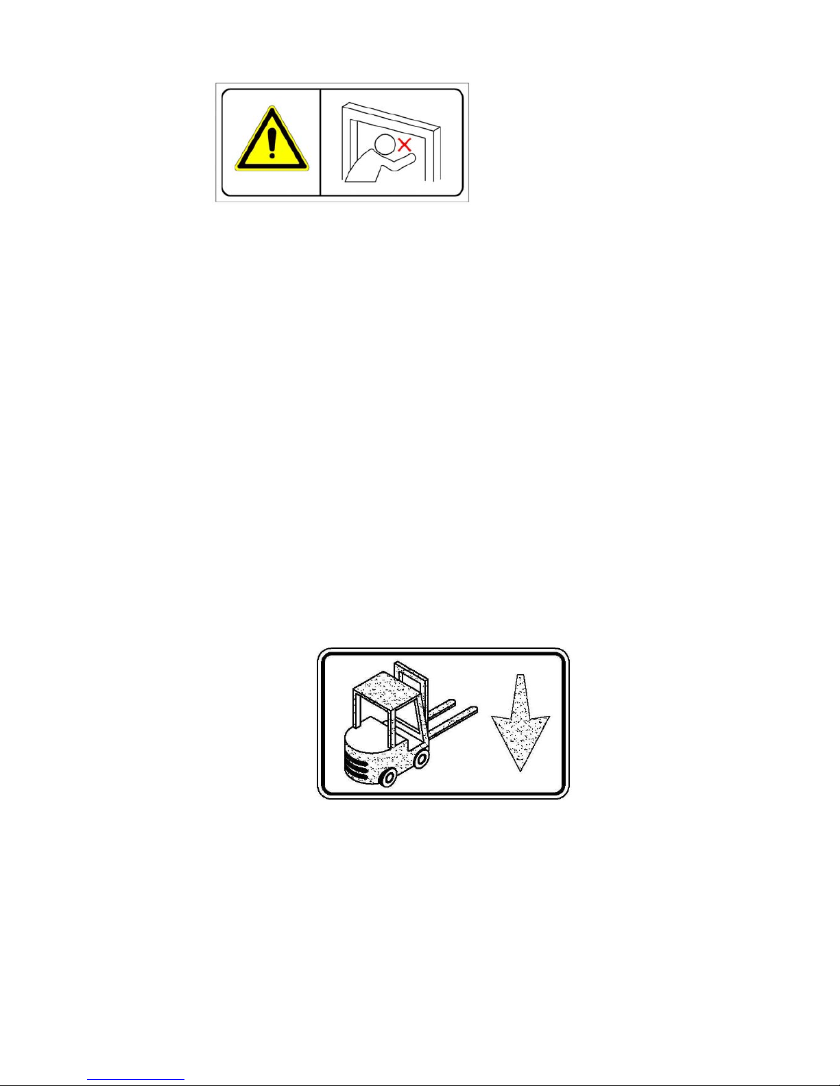
8. How to Safely move the Machine.................................................... 26
9. Troubleshooting ............................................................................... 27
10. Wiring Diagram ............................................................................... 28

- 1 -
1. Safety Instructions
(1) Before Operating
a. Read the instruction manual.
b. Wear eye protection and safety gloves before operating this machine.
Eye protection must be worn Safety gloves must be worn Ear-protector must be worn
c. Verify that the power line voltage is correct.
d. The machine must be properly grounded to avoid a shock hazard.All wiring must be in
accordance with local wiring standards.
e. The strapping machine can only be operated with polypropylene (P.P.) strapping; do not
use polyester (PET) strapping or polyethylene (PE) cord strap.
(2) During operating
a. The weight of the package cannot exceed 100 kg (220 lbs),
b. The size of the package should not be less than 130mm (width) × 20mm (high) (5.1” ×
0.79”).
c. Check if the machine emits any smokes or unusual sound when it is running.
d. Keep away from the inside of the arch while the machine is operating; do not put your
hands or body into the arch when the machine is running.
(3) After operating
a. Remove dust and dirt from the unit; pay particular attention to the interior of the arch.
b. Turn off the power when the machine is not in use.
(4) Signs
Caution!
Electric Shock Hazard
Caution!
Hot!
Do not touch!

- 2 -
(5) Maintenance
a. Turn off the power before removing either of the top covers.
b. The heater tongue is very hot; do not touch it.
(6) Storage
a. The store room must be dry.
b. Do not expose the machine to extreme cold or heat environment.
c. Place the machine on an even floor in order to avoid any distortion.
(7) Other Reminders
a. A operation manual must remain attached to the machine at all times.
b. Do not alter the equipment or circuitry unless authorized to do so by the manufacturer.
(8) Attention
When the machine arrives in your warehouse, you need to use a forklift to take it off from
the pallet. If you could go down to the bottom side of the machine, you would see an
indication sticker as follows: (TP-601L)
Follow this sticker and lead the teeth of a forklift to that indicated position. After making
few distance adjusting, you then could drive the teeth in and take off the machine.
Warning for danger!
Do not put your hands or body
into arch working area when
machine is operating.

- 3 -
2. Construction and Function of Units
a. TP-601D
6 Electric control unit
2 Bandway unit
This is the arch track through which
P.P. strap forwards or reverses.
8 Auto strap feeding unit
3 Accumulator unit
This unit accumulates the quantity of strap
required for smooth feeding into the chute track.
5 Body frame unit
1 Strapping head unit
This unit is the most important part of
the machine for cutting and sealing of
P.P.
4 Reel unit
Holds the strap coil. (If strap
core is 280mm, you can take
off the center drum to have
core size 200mm.)

- 4 -
b. TP-601L
4 Reel unit
Holds the strap coil.
(If strap core is 280mm, you can take off the
center drum to have core size 200mm.)
6 Electric control unit
5 Body frame unit 1 Strapping head unit
This unit is the most important part of the
machine for cutting and sealing of P.P. strap.
8 Auto strap feeding
2 Bandway unit
This is the arch track
through which P.P. strap
forwards or reverses.
3 Accumulator unit
This unit accumulates the
quantity of strap required for
smooth feeding into the chute
track.

- 5 -
3. General Safety Remarks
(1) Basic Operation
The machine is only to be operated when in good running condition and in accordance
with the instructions provided in the operation manual. Operators must be trained in
proper operation and safety of the equipment.
The machine may only be operated in accordance with its designated use.
(2) Basic Safety Precautions
In addition to the instructions for operation, the user is to be instructed in all generally
applicable legal or mandatory regulations relevant to safety or the environment.
Long hair, loose-fitting garments, or jewelry can be a safety hazard. These items must be
secured prior to equipment operation.
Use protective equipment whenever appropriate or when required by law.
Carefully observe all safety instructions and warnings attached to the machine. Keep
safety labels clean and legible.
People that are being trained to operate or service the equipment must be supervised by
experienced personnel.
Any electrical work performed on the equipment must be conducted by a skilled
electrician or under the supervision of a skilled electrician. All work must observe good
electrical engineering practice and follow safety rules and local wiring standards.
(3) Safety Instructions Governing Specific Operational Phases
Avoid unsafe operation of the equipment.
The machine is only to be operated when it is in good running order. Only operate the
equipment in a safe manner; all protective and safety devices must be in place and fully
functional. This includes removable safety devices, emergency shut-off equipment,
noise-protection devices and exhaust fans.
The machine is to be checked for damage and defects at least once each work shift. Any
changes, including the working behavior of the machine, are to be reported immediately. If
necessary, the machine is to be stopped and locked-out immediately.
In case of a malfunction, the strapping machine is to be immediately stopped and
locked-out until the fault has been eliminated.

- 6 -
Before starting the strapping machine, make sure that the area is clear and safe.
Operating personnel need to be briefed before executing special operations and
maintenance work; this work needs to be done with the proper supervision.
Always check and tighten connections after maintenance or repair.
After completing maintenance or repair, all safety devices must be replaced and checked
for functionality before operating the equipment.
To minimize the environmental impact, all consumables and replaced parts must be
disposed of safely.
Before starting the machine, check that the accessories have been stowed away safely.
Avoid operating the machine in a fashion that could upset its stability.
(4) Warning of Electrical Dangers
Electrical Energy
Immediately remove power to the machine in case of trouble in the electrical system.
Replace a fuse with one with the same style and ratings; pay particular attention to
matching the specified current.
Any electrical work performed on the equipment must be conducted by a skilled
electrician or under the supervision of a skilled electrician. All work must observe good
electrical engineering practice and follow safety rules and local wiring standards.
Inspect the electrical equipment of the machine at regular intervals. Tighten any loose
connections. Check wiring for scorch marks; replace scorched wiring and determine and
correct the reason for the overheating.
When working on live equipment, ensure that a second person is available to cut power in
case of an emergency. When appropriate, secure the working area with safety tape and a
warning sign. Use insulated tools for electrical work.
Before working on high-voltage assemblies, turn off the power supply. Carefully discharge
the supply cable and short-circuit any energy-storage components such as capacitors.
If the equipment was moved, carefully refit and refasten all parts removed for transport
before reapplying power.
Before moving the machine, remember to disconnect the power cable.

- 7 -
(5) Grounding Instructions Shall Include the Following
This product must be grounded. In the event of an electrical short circuit, grounding
reduces the risk of electric shock. This product is equipped with a cord that has a
grounding wire and an appropriate grounding plug. The plug must be plugged into an
outlet that is properly installed and grounded in accordance with all local codes and
ordinances.
If repair or replacement of the cord or plug is necessary, connect the ground wire to the
ground terminal of the plug. The wire with green insulation (with or without yellow stripes)
is the grounding wire.
Check with a qualified electrician or service person if the grounding instructions are not
clear or if in doubt about the proper grounding of the machine. Do not modify the plug
provided; if it will not fit the power outlet, have the proper outlet installed by a qualified
electrician.
DANGER!
Improper installation of the grounding can result in electrocution.

- 8 -
4. Machine Information
(1) Areas of Application and Machine Description
This plastic strapping machine can be used for all types of strapping applications with
package sizes of 130 mm(width) × 20 mm(height) and up.
This machine is particularly suitable for heavy packaged goods as well as printed products,
boxes, etc.
Machine Description
Automatic plastic strapping machine for use with polypropylene strapping
Extra tough construction
Simple, safe and user-friendly operation
Automatic feeding-system
Automatic strap-end detection
Loop ejection
Mobile, with large table area and high capacity strap reel
Table surface made of stainless steel
Strap tension adjustable from soft to extremely high
Environment Information
The strapping machine shall be installed in the following conditions:
zSupply voltage: 0.9 - 1.1 nominal supply voltage
zSource frequency: 0.99 - 1.01 nominal frequency
zAmbient temperature: 5°C - 40°C (41℉-104℉).
zRelative humidity: not exceed 50% at 40°C.
zPlease provide a suitable illumination around the machine for safety operation.

- 9 -
(2) Technical Data
a. TP-601D
Sealing method : Heat
Strap width : 8 mm to 12 mm (3/8" - 1/2")
Strap thickness : 0.55 mm up to 0.75 mm (0.022" - 0.03")
Strap reel diameter : 200 mm (8" nominal)
Width : 1430 mm (56.3")
Depth : 620 mm (24.4")
Table height : 810 mm (31.9")
Electrical connection : AC 110V/220V/230V/240V (50/60Hz), 1PH
AC 220V/380V/400V (50/60Hz), 3PH
Weight : 220 kg (485 lbs.)
Noise emission : 83 dB (A)
Ambient temp : 5℃~ 40℃(41℉~104℉)

- 10 -
b. TP-601L
Sealing method : Heat
Strap width : 8 mm to 12 mm (3/8" - 1/2")
Strap thickness : 0.55 mm up to 0.75 mm (0.022" - 0.03")
Strap reel diameter : 200 mm (8" nominal)
Width : 1880 mm (74")
Depth : 620 mm (24.4")
Table height : 410 mm (16.1")
Electrical connection : AC 110V/220V/230V/240V (50/60Hz), 1PH
AC 220V/380V/400V (50/60Hz), 3PH
Weight : 235 kg (518.1 lbs.)
Noise emission : 83 dB (A)
Ambient temp : 5℃~ 40℃(41℉~104℉)

- 11 -
(3) Control Panel
○
1 Start Switch
This is the switch to start a strapping operation.
A strapping cycle is completed only after
actuation of this switch. (Indicator for strap goes
to ready position)
○
2 Reset switch
This is the switch to activate auto strap feeding.
In addition, it is used for troubleshooting. If
the strap is mis-fed, you can push this button to
solve the problem.
○
3 selector switch
While selector switch is placed to the position
, the machine will automatically strap the
package when it is placed on the table and passes
the chute arch, if the package remains under the
arch, the strapping cycle will continue. While
the selector switch is placed to the position ,
after positioning the package under the arch,
push the "START" switch, then one strap will be
applied.
○
4 Tension Adjustment Knob
External adjustment of strap tension by
step-by-step rotation of this knob.
TP-601L
TP-601D

- 12 -
(4) Electric Control Unit
Timer, T1 ○
30 :
T1 timer determines the time necessary for strap take-up. While setting, please test with
the minimum sized package. Normally, Timer T1 is set at about 0.5 second, but may
have to be adjusted depending on arch size & actual package size.
TP-601D1
TP-601L1
TP-601D3
TP-601L3

- 13 -
5. Operating the Machine
(1) Operation Space
Keep the area (A) and (B) free for the operator.
The area (A) is necessary for operation strapping machine and the area (B) is necessary
for changing the strap or adjusting strap amount in the accumulator.
A
B

- 14 -
(2) Installation ofArch Unit (For TP-601D)
Table of contents
Other Peak Tools manuals