TruVision TVK-600 Instruction sheet

TVK-600 Configuration
Manual
P/N 1073652-EN • REV B • ISS 04FEB22

Copyright
©
2022 Carrier. All rights reserved.
Specifications subject to change without
prior notice
.
This document may not be copied in whole or in part or otherwise
reproduced without prior written consent from
Carrier, except where
specifically permitted under US and international copyright law.
Trademarks and
patents
TruVision
names and logos are a product brand of Aritech, a part of Carrier
.
Other trade names used in this document may be trademarks or registered
trademarks of the manufacturers or vendors of the respective products.
Manufactu
rer
PLACED ON THE MARKET BY:
Carrier Fire & Security Americas Corporation Inc.
13995 Pasteur Blvd, Palm Beach Gardens, FL 33418, USA
AUTHORIZED EU REPRENSENTATIVE:
Carrier Fire & Security B.V.
Kelvinstraat 7, 6003 DH Weert, Netherlands
FCC compliance
Cl
ass A: This equipment has been tested and found to comply with the
limits for a Class A digital device, pursuant to part 15 of the FCC Rules.
These limits are designed to provide reasonable protection against harmful
interference when the equipment is oper
ated in a commercial environment.
This equipment generates, uses, and can radiate radio frequency energy
and, if not installed and used in accordance with the instruction manual,
may cause harmful interference to radio communications. Operation of this
equ
ipment in a residential area is likely to cause harmful interference in
which case the user will be required to correct the interference at his own
expense.
FCC conditions
This device complies with Part 15 of the FCC Rules. Operation is subject to
the fo
llowing two conditions:
(1) This device may not cause harmful interference.
(2) This Device must accept any interference received, including
interference that may cause undesired operation.
ACMA compliance
Notice!
This is a Class A product. In a domestic environment this product
may cause radio interference in which case the user may be required to
take adequate measures.
Product warnings and
disclaimers
THESE PRODUCTS ARE INTENDED FOR SALE TO AND
INSTALLATION BY QUALIFIED PROFESSIONALS. CARRI
ER FIRE &
SECURITY CANNOT PROVIDE ANY ASSURANCE THAT ANY PERSON
OR ENTITY BUYING ITS PRODUCTS, INCLUDING ANY “AUTHORIZED
DEALER” OR “AUTHORIZED RESELLER”, IS PROPERLY TRAINED OR
EXPERIENCED TO CORRECTLY INSTALL FIRE AND SECURITY
RELATED PRODUCTS.
For more
information on warranty disclaimers and product safety
information, please check https://firesecurityproducts.com/policy/product
-
warning/ or scan the following code:
Certification
EU directives
This product and
- if applicable - the supplied accessories too are marked
with "CE" and comply therefore with the applicable harmonized European
standards listed under the EMC Directive 2014/30/EU, the RoHS Directive
2011/65/EU.

2012/19/EU (WEEE directive):
Products marked with this symbol cannot
be disposed of as unsorted municipal waste in the European Union. For
proper recycling, return this product to your local supplier upon the
purchase of equivalent new equipment, or dispose of it at designated
collection points. For more information
see: www.recyclethis.info.
2013/56/EU & 2006/66/EC (battery directive
): This product contains a
battery that cannot be disposed of as unsorted municipal waste in the
European Union. See the product documentation for specific battery
information. The battery is marked with this symbol, which may include
lettering to indicate cadmium (Cd), lead (Pb), or mercury (Hg). For proper
recycling, return the battery to your supplier or to a designated collection
point. For more information see:
www.recyclethis.info.
Contact information
EMEA:
https://firesecurityproducts.com
Australian/New Zealand:
https://firesecurityproducts.com.au/
Product
documentation
Please consult the following web link to retrieve the electronic version of the
product documentation.
The manuals are available in several languages.


TVK-600 Configuration Manual i
Content
Important information iii
Limitation of liability iii
Product Warnings iii
Warranty Disclaimers iv
Intended Use v
Advisory messages v
Introduction 6
Product overview 6
Installation environment 6
Package contents 6
Contact information, firmware and manuals 7
Keypad description 8
Keypad connections 8
Joystick operation 8
Function keys 9
Enter alphanumeric values 9
Getting started 10
Checking your web browser security level 10
Activate the admin password 11
Access the keypad functions using the browser 12
Access the keypad functions using the keypad 14
Device management using the browser 15
Add, edit, or delete a device 15
Search for devices and add to the keypad 17
Import/export an input device list 18
Camera groups 20
Manage an output channel for keyboard mode 21
System management using the browser 24
Version information 24
User management 24
Maintenance 26
Network management using the browser 28
Serial port settings using the browser 29
System menu of the keypad 30
Version menu 30
Network menu 30
User management 30

ii TVK-600 Configuration Manual
Serial port 31
Hardware 31
Time 31
Maintenance 31
Keypad operation 33
Keypad modes to control a device 33
How to use device and camera IDs 34
Multiscreen options 36
Information to provide to the operator 37
Control a camera using Keyboard mode 38
Control a recorder using DVR by IP mode 41
Control a recorder using DVR by RS-485 mode 44
Control a dome camera using Dome by RS-485 mode 47
Appendix A: List of supported devices by keypad mode 49

TVK-600 Configuration Manual iii
Important information
Limitation of liability
To the maximum extent permitted by applicable law, in no event will Carrier be liable for
any lost profits or business opportunities, loss of use, business interruption, loss of
data, or any other indirect, special, incidental, or consequential damages under any
theory of liability, whether based in contract, tort, negligence, product liability, or
otherwise. Because some jurisdictions do not allow the exclusion or limitation of liability
for consequential or incidental damages the preceding limitation may not apply to you.
In any event the total liability of Carrier shall not exceed the purchase price of the
product. The foregoing limitation will apply to the maximum extent permitted by
applicable law, regardless of whether Carrier has been advised of the possibility of such
damages and regardless of whether any remedy fails of its essential purpose.
Installation in accordance with this manual, applicable codes, and the instructions of the
authority having jurisdiction is mandatory.
While every precaution has been taken during the preparation of this manual to ensure
the accuracy of its contents, Carrier assumes no responsibility for errors or omissions.
Product Warnings
YOU UNDERSTAND THAT A PROPERLY INSTALLED AND MAINTAINED
ALARM/SECURITY SYSTEM MAY ONLY REDUCE THE RISK OF EVENTS SUCH AS
BURGLARY, ROBBERY, FIRE, OR SIMILAR EVENTS WITHOUT WARNING, BUT IT
IS NOT INSURANCE OR A GUARANTEE THAT SUCH EVENTS WILL NOT OCCUR
OR THAT THERE WILL BE NO DEATH, PERSONAL INJURY, AND/OR PROPERTY
DAMAGE AS A RESULT.
THE ABILITY OF CARRIER PRODUCTS, SOFTWARE OR SERVICES TO WORK
PROPERLY DEPENDS ON A NUMBER OF PRODUCTS AND SERVICES MADE
AVAILABLE BY THIRD PARTIES OVER WHICH CARRIER HAS NO CONTROL AND
FOR WHICH CARRIER SHALL NOT BE RESPONSIBLE INCLUDING, BUT NOT
LIMITED TO, INTERNET, CELLULAR AND LANDLINE CONNECTIVITY; MOBILE
DEVICE AND OPERATING SYSTEM COMPATIBILITY; MONITORING SERVICES;
ELECTROMAGNETIC OR OTHER INTERFERENCE, AND PROPER INSTALLATION
AND MAINTENANCE OF AUTHORIZED PRODUCTS (INCLUDING ALARM OR
OTHER CONTROL PANEL AND SENSORS).
ANY PRODUCT, SOFTWARE, SERVICE OR OTHER OFFERING MANUFACTURED,
SOLD OR LICENSED BY CARRIER, MAY BE HACKED, COMPROMISED AND/OR
CIRCUMVENTED AND CARRIER MAKES NO REPRESENTATION, WARRANTY,
COVENANT OR PROMISE THAT ITS PRODUCTS (INCLUDING SECURITY
PRODUCTS), SOFTWARE, SERVICES OR OTHER OFFERINGS WILL NOT BE
HACKED, COMPROMISED AND/OR CIRCUMVENTED.
CARRIER DOES NOT ENCRYPT COMMUNICATIONS BETWEEN ITS ALARM OR
OTHER CONTROL PANELS AND THEIR WIRELESS OUTPUTS/INPUTS INCLUDING

iv TVK-600 Configuration Manual
BUT NOT LIMITED TO, SENSORS OR DETECTORS UNLESS REQUIRED BY
APPLICABLE LAW. AS A RESULT THESE COMMUNICATIONS MAY BE
INTERCEPTED AND COULD BE USED TO CIRCUMVENT YOUR ALARM/SECURITY
SYSTEM.
THE EQUIPMENT SHOULD ONLY BE OPERATED WITH AN APPROVED POWER
ADAPTER WITH INSULATED LIVE PINS.
DO NOT CONNECT TO A RECEPTACLE CONTROLLED BY A SWITCH.
THIS UNIT INCLUDES AN ALARM VERIFICATION FEATURE THAT WILL RESULT
IN A DELAY OF THE SYSTEM ALARM SIGNAL FROM THE INDICATED CIRCUITS.
THE TOTAL DELAY (CONTROL UNIT PLUS SMOKE DETECTORS) SHALL NOT
EXCEED 60 SECONDS. NO OTHER SMOKE DETECTOR SHALL BE CONNECTED
TO THESE CIRCUITS UNLESS APPROVED BY THE LOCAL AUTHORITY HAVING
JURISDICTION.
WARNING! The equipment should only be operated with an approved power adapter
with insulated live pins.
Caution: Risk of explosion if battery is replaced by an incorrect type. Dispose of
batteries according to the instructions. Contact your supplier for replacement batteries.
Warranty Disclaimers
CARRIER HEREBY DISCLAIMS ALL WARRANTIES AND REPRESENTATIONS,
WHETHER EXPRESS, IMPLIED, STATUTORY OR OTHERWISE, INCLUDING ANY
IMPLIED WARRANTIES, THE WARRANTIES OF MERCHANTABILITY OR FITNESS
FOR A PARTICULAR PURPOSE.
(USA only) SOME STATES DO NOT ALLOW THE EXCLUSION OF IMPLIED
WARRANTIES, SO THE ABOVE EXCLUSION MAY NOT APPLY TO YOU. YOU MAY
ALSO HAVE OTHER LEGAL RIGHTS THAT VARY FROM STATE TO STATE.
CARRIER DOES NOT MAKE ANY CLAIMS OR WARRANTIES TO YOU OF ANY
KIND REGARDING ANY PRODUCT, SOFTWARE OR SERVICE’S POTENTIAL,
ABILITY, OR EFFECTIVENESS TO DETECT, MINIMIZE, OR IN ANYWAY PREVENT
DEATH, PERSONAL INJURY, PROPERTY DAMAGE, OR LOSS OF ANY KIND
WHATSOEVER.
CARRIER DOES NOT REPRESENT TO YOU THAT ANY PRODUCT (INCLUDING
SECURITY PRODUCTS), SOFTWARE, SERVICE OR OTHER OFFERING MAY NOT
BE HACKED, COMPROMISED AND/OR CIRCUMVENTED.
CARRIER DOES NOT WARRANT THAT ANY PRODUCT (INCLUDING SECURITY
PRODUCTS), SOFTWARE OR SERVICE MANUFACTURED, SOLD OR LICENSED
BY CARRIER WILL PREVENT, OR IN ALL CASES PROVIDE ADEQUATE WARNING
OF OR PROTECTION FROM, BREAK-INS, BURGLARY, ROBBERY, FIRE, OR
OTHERWISE.

TVK-600 Configuration Manual v
CARRIER DOES NOT WARRANT TO YOU THAT ITS SOFTWARE OR PRODUCTS
WILL WORK PROPERLY IN ALL ENVIRONMENTS AND APPLICATIONS AND DOES
NOT WARRANT ANY PRODUCTS AGAINST HARMFUL ELECTROMAGNETIC
INTERFERENCE INDUCTION OR RADIATION (EMI, RFI, ETC.) EMITTED FROM
EXTERNAL SOURCES
CARRIER DOES NOT PROVIDE MONITORING SERVICES FOR YOUR
ALARM/SECURITY SYSTEM (“MONITORING SERVICES”). IF YOU ELECT TO HAVE
MONITORING SERVICES YOU MUST OBTAIN SUCH SERVICE FROM A THIRD
PARTY AND CARRIER MAKES NO REPRESENTATION OR WARRANTY WITH
RESPECT TO SUCH SERVICES INCLUDING WHETHER OR NOT THEY WILL BE
COMPATIBLE WITH THE PRODUCTS, SOFTWARE OR SERVICES
MANUFACTURED, SOLD OR LICENSED BY CARRIER.
Intended Use
Use this product only for the purpose it was designed for; refer to the data sheet and
user documentation. For the latest product information, contact your local supplier or
visit us online at firesecurityproducts.com.
The system should be checked by a qualified technician at least every 3 years and the
backup battery replaced as required.
Advisory messages
Advisory messages alert you to conditions or practices that can cause unwanted
results. The advisory messages used in this document are shown and described below.
WARNING: Warning messages advise you of hazards that could result in injury or loss
of life. They tell you which actions to take or to avoid in order to prevent the injury or
loss of life.
Caution: Caution messages advise you of possible equipment damage. They tell you
which actions to take or to avoid in order to prevent the damage.
Note: Note messages advise you of the possible loss of time or effort. They describe
how to avoid the loss. Notes are also used to point out important information that you
should read.

6 TVK-600 Configuration Manual
Introduction
Product overview
The TruVision TVK-600 keypad lets you communicate using RS-485 or IP with
TruVision recorders, decoders, encoders and PTZ domes. You can easily control the
devices.
The keypad is easily configured and operated through the web browser.
Installation environment
When installing your product, consider these factors:
Ventilation: Do not block any ventilation openings. Install in accordance with the
manufacturer’s instructions. Ensure that the location planned for the installation of the
unit is well ventilated.
Temperature: Consider the unit’s operating temperature (-10 to +55 ºC, 14 to 131 °F)
and noncondensing humidity specifications (10 to 90%) before choosing an installation
location. Extremes of heat or cold beyond the specified operating temperature limits
may reduce the life expectancy of the recorder. Do not install the unit on top of other
hot equipment. Leave 44 mm (1.75 in.) of space between rack-mounted DVR units.
Moisture: Do not use the unit near water. Moisture can damage the internal
components. To reduce the risk of fire or electric shock, do not expose this unit to rain
or moisture.
Chassis: Equipment weighing less than 15.9 kg (35 lb.) may be placed on top of the
unit.
Package contents
When you receive the product, check the package and contents for damage, and verify
that all items are included. If any of the items are damaged or missing, please contact
your local supplier.
The TVK-600 is shipped with the following items:
• TVE-600 keypad
• Power supply unit (PSU)
• Power supply cords (US, UK and Europe)
• TruVision TVK-600 Quick Start Guide
You can download the software and the manual from our web site. Also available from
our web site are these guides in several languages:
• TruVision TVK-600 Configuration Manual
• TruVision TVK-600 Operator Guide: Keyboard Mode
• TruVision TVK-600 Operator Guide: DVR by IP Mode

TVK-600 Configuration Manual 7
• TruVision TVK-600 Operator Guide: DVR by RS-485 Mode
• TruVision TVK-600 Operator Guide: DOME by RS-485 Mode
Contact information, firmware and manuals
For contact information and to download the latest manuals, tools, and firmware, go to
the web site of your region.
EMEA: https://firesecurityproducts.com
Manuals are available in several languages.
Australia/New Zealand: https://firesecurityproducts.com.au/
8 TVK-600 Configuration Manual
Keypad description
This chapter describes how to connect the keypad and use the joystick.
Keypad connections
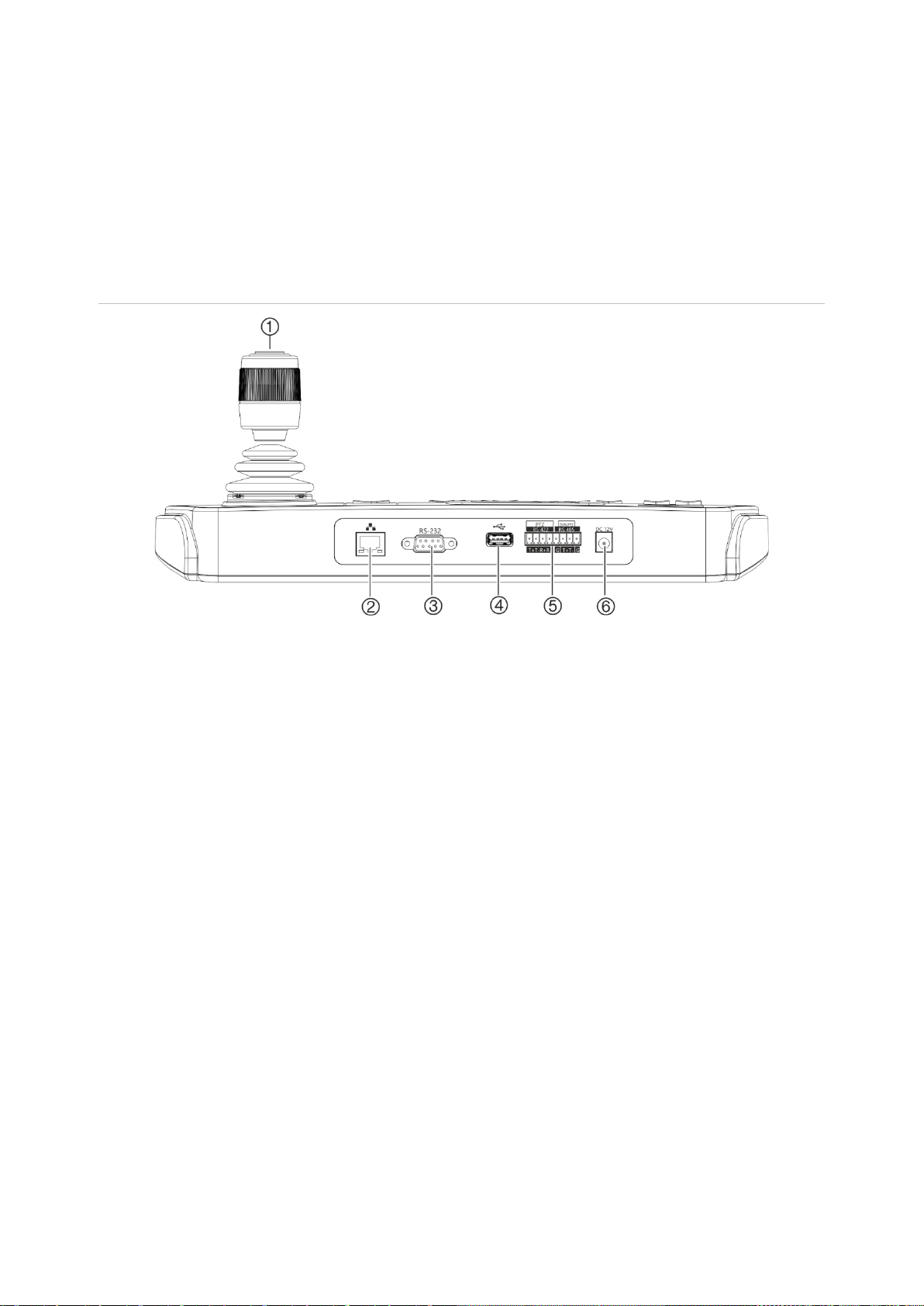
Figure 1: Back panel
1. 4-axis joystick with button on top
2. Network port
10/100 Mbps Ethernet interface
3. RS-232 serial interface
4. USB interface
5. RS-422/RS-485 serial interface (RS-422 not
in use)
6. 12 VDC power connector
Joystick operation
In System menu mode:
• Move it up/down to select the desired submenu.
• Move it left/right to modify items in the submenu.
• Press the center button on the joystick to confirm.
In Shortcut menu mode:
• Move the joystick in one of eight directions to control pan/tilt. Rotate the knob for
zoom control.
• Press the center button on the joystick for the Enter function and to capture
snapshots. Save the snapshots to a USB flash drive.
TVK-600 Configuration Manual 9
Function keys
The keypad function keys allow you to quickly select regularly used functions such as to
call up presets or to select a monitor.
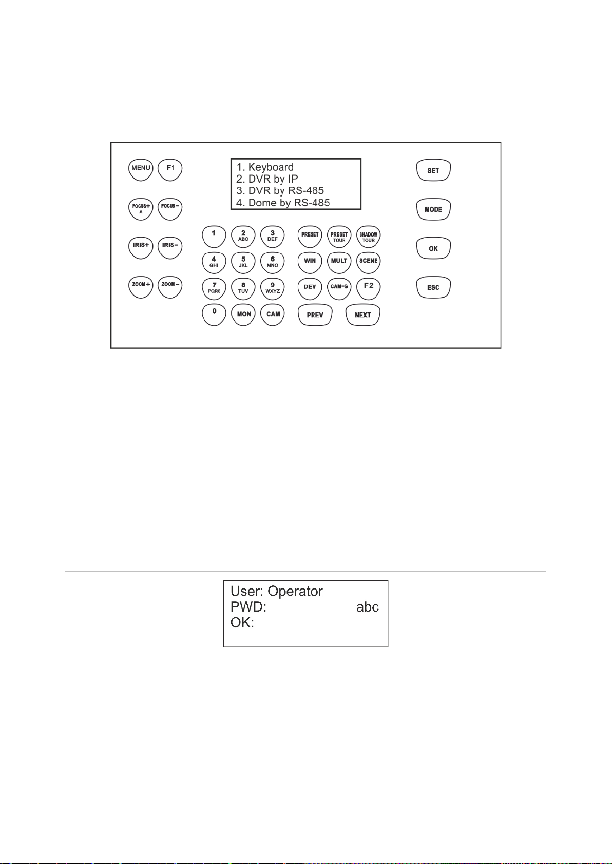
Figure 2: Keypad button layout
See “Keypad operation” on page 30 for a description of the keypad functions.
Enter alphanumeric values
When using the keypad’s functions, you can enter both numbers and letters in the LCD
display using the alphanumeric buttons on the keypad. To toggle between numbers,
lower case letters, and All Caps letters, press the FOCUS + A button.
The FOCUS+ button by default is set to enter numbers. When pressed once, it then
enters lower case letters and “abc” appears on screen. Pressed twice, it enters capital
letters and “ABC” appears on screen. When enabled to enter letters, press the numeric
button for the desired letter.
Figure 3: Keypad LCD set to enter lower case letters

10 TVK-600 Configuration Manual
Getting started
Use the web browser to access and configure the keypad over the network.
Checking your web browser security level
When using the web browser interface, you can install ActiveX controls to connect and
view video using Internet Explorer (the keypad is not compatible with Microsoft Edge).
However, you may not be able to download data, such as video and images, due to the
browser’s security settings. Consequently, you should check the security level of your
browser so that you are able to interact with the cameras over the web and, if
necessary, modify the Active X settings.
Configuring IE ActiveX controls
You should confirm the ActiveX settings of your web browser.
To change the web browser’s security level:
1. In Internet Explorer (IE) click Internet Options on the Tools menu.
2. On the Security tab, click the zone to which you want to assign a web site under
“Select a zone to view or change security settings”.
3. Click Custom Level.
4. Change the ActiveX controls and plug-in options that are signed or marked as
safe to Enable. Change the ActiveX controls and plug-ins options that are
unsigned to Prompt or Disable. Click OK.
- or -
Under Reset Custom Settings, click the security level for the whole zone in the
Reset To box, and select Medium. Click Reset.
Then click OK to open the Internet Options Security tab window.
5. Click Apply.
Windows users
Internet Explorer operating systems have increased security measures to protect your
PC from any malicious software being installed.
To have complete functionality of the web browser interface with Windows 7, 8 and 10,
do the following:
• Run the browser interface as an administrator in your workstation
• Add the keypad’s IP address to your browser’s list of trusted sites
To add the keypad’s IP address to Internet Explorer’s list of trusted sites:
1. Open Internet Explorer.
2. Click Tools, and then Internet Options.

TVK-600 Configuration Manual 11
3. Click the Security tab, and then select the Trusted sites icon.
4. Click the Sites button.
5. Clear the “Require server verification (https:) for all sites in this zone box”.
6. Enter the IP address in the “Add this website to the zone” field.
7. Click Add, and then click Close.
8. Click OK in the Internet Options dialog window.
9. Connect to the keypad for full browser functionality.
Activate the admin password
When you first start up the unit, the Activation window appears. You must define a high-
security admin password before you can access the unit. There is no default password
provided.
A message will appear on-screen when the unit has been activated.
Tips on creating a strong password:
A valid password range must have up to eight characters. You can use a
combination of numbers, and lower- and upper-case letters. No special characters
or spaces are permitted. The password must contain characters from at least two of
these groups.
The password is case-sensitive so use a mixture of upper- and lower-case letters.
Do not use personal information or common words as a password.
Note: If you should forget your admin password, please contact Technical Support to
reactivate the unit with a new password.
Go to “User management” on page 24 for further information on creating extra users.
Default network settings:
The network settings are:
• IP address - 192.168.1.70
• Subnet mask - 255.255.255.0
• Gateway address - 192.168.1.1
• HTTPS port: 443

12 TVK-600 Configuration Manual
Access the keypad functions using the browser
To access the keypad functions using the browser:
1. Once the keypad has been activated, enter the keypad’s IP address
(https://address) in the web browser. Use the TruVision Device Manager to find the
IP address of the keypad and assign it a new address on the local network, if
desired.
Note: When using Device Manager, it will list the devices found but they will not be
accessible by the keypad as the link is not a secure IP address. You must change
the IP address to https://.
2. If this is first time you are accessing the keypad, you will see a “This site is not
secure” warning. Click More Information and then, under the extra information that
appears, click Go on to the webpage.
The Login dialog box appears.
Note: Ensure that the Active X controls are enabled.
3. Select your language. English is default.
Note: The user interface in the browser is available is several languages. However,
the display on the keypad screen is only available in English.
4. Enter your user name and password as administrator and click Login.

TVK-600 Configuration Manual 13
Note: In the Login dialog box, if you enter the wrong password seven times for
admin user or five times for operators, the user account will be locked for 30
minutes.
The browser menu appears. By default, the Device Management menu appears
(see Figure 4 below).
Browser menu overview
You can configure the keypad using the browser. Only the administrator can access
this menu.
Figure 4: Browser menu overview (Device Management shown)
Menu function Description
1.
Device Management
There are three submenus to manage devices and channels.
Device List: Add, modify, and delete a device: IPC/IP Dome, DVR/NVR,
and decoder. “IPC” is an IP camera.
Input Channel: Manage the input channel lists and groups.
Output Channel (for keyboard mode): Manage output channel
information.
DVR-By-IP output list
: Manage the ID for the recorder's monitor outputs for
the mode “DVR-By-IP”.
See “Device management” on page 15 for further information on this menu.
2.
System Management
There are three submenus.
Version: Display the device version and licenses.
User management: Add, edit, and delete a user, add and delete devices
associated with a user, and change the password.
Maintenance: Remotely reboot, restore factory settings, export the config
file, and remotely upgrade the firmware.
See “System management” on page 24 for further information on this menu.

14 TVK-600 Configuration Manual
Menu function Description
3.
Network Management
Manage all network related aspects of the device including general network
settings, such as IP address, gateway address, and subnet mask.
See “Network management” on page 28 for further information on this
menu.
4.
Serial Port Settings
Set up the parameters of the RS-485 port.
See “Serial port settings” on page 29 for further information on this menu.
Access the keypad functions using the keypad
The keypad has two menu modes, System and Shortcut. See Figure 5 below.
The System menu allows you to quickly access the most frequently used settings to
configure the keypad. This menu is only available to the administrator.
The Shortcut menu is used to operate the keypad. This menu can be accessed by both
the administrator and operators.
Note: The display on the keypad screen is only available in English.
Figure 5: Keypad menu tree
To access the keypad functions using the keypad:
1. Log in to the keypad.
2. As administrator you can access two menus using the LCD display.
Click System to configure the keypad. See “System menu of the keypad” on page
30 for further information on using this menu.
- or -
Click Shortcut to operate the keypad. See “Keypad operation” on page 33 for more
information.
Note: The keypad menus time out after five minutes.

TVK-600 Configuration Manual 15
Device management using the browser
The Device Management menu describes how you can add, modify, or delete a device
using the browser. You can also search for online devices.
This menu is only available to the administrator.
Add, edit, or delete a device
You can add, edit, and delete IP dome cameras, DVR/NVRs, an encoder, and a
decoder. You can also search the network for devices to add.
The devices connected to the keypad do not support all four keypad modes. See
Table 7 on page 49 for the list of supported devices by keypad mode.
Before you use the keypad, you must first add the desired devices that you want to
control with it. Once you have created the devices under Device Management > Device
List, you can then go to the Input Channel and Output Channel menus to make any
changes to the devices.
Note: It is important that you keep a back up file of the devices you add to the keypad.
We recommend that you create a backup file in Excel format after adding a couple of
devices and export the file as a template. See “Import/export an input device list” on
page 18 for further information.
Channel and device ID
Every device added to the keypad is automatically allocated a unique ID by the system.
Cameras get an input channel ID. Recorders and decoders get a device ID. The ID is
allocated a number in the order in which the device is added to the keypad, irrespective
if it is a camera, recorder or decoder. For example, if you add two recorders to the
keypad, they will be allocated the device IDs 1 and 2. If you then add a decoder, it will
get device ID 3. If you then add a third recorder, it is device ID 4.
You can easily change the ID number under Edit in the Device Management menu.
Before changing the ID numbers of devices, you should first export to an Excel file the
list of devices configured in the keypad so that you can see what camera has been
allocated which ID number. It is not possible to export a list of the recorders, decoders
or monitor IDs. To find their IDs, you need to look at the Device Management screens
for these devices.
For further information on channel and device IDs and how they are used, see “How to
use device and camera IDs” on page 34.

16 TVK-600 Configuration Manual
To add, edit or delete devices:
1. Log in to the keypad. Go to Device Management > Device List.
2. In the Device Management > Device List window, select the tab for the desired
device type: IPC/IP Dome, DVR/NVR, or Decoder. “IPC” is an IP camera.
Note: Encoder channels are added as input channels.
3. Click Add. The Add Device window pops up.
4. Select how you want to add the device: by IP or IP segment. An IP Segment is the
range of IP addresses to be used.
Note: The server port is 8000 by default.
5. Enter the network parameters and click OK.
The device is then added to the device window (IPC/IP Dome, DVR/NVR, or
Decoder).
Example of the cameras added under IPC/IP Dome is shown below:
Other manuals for TVK-600
3
Table of contents


