YASKAWA JZSP-GA500 User manual

MANUAL NO. TOEP C720600 05B
Yaskawa AC Drive Option
LCD Keypad Attachment
Installation Manual
Model JZSP-GA500
To properly use the product, read this manual thoroughly and retain for
easy reference, inspection, and maintenance. Ensure the end user
receives this manual.

This Page Intentionally Blank
2YASKAWA TOEP C720600 05B LCD Keypad Attachment Installation Manual

YASKAWA TOEP C720600 05B LCD Keypad Attachment Installation Manual 3
Table of Contents
1. Receiving . . . . . . . . . . . . . . . . . . . . . . . . . . . . . . . . . . . . . . . . . . . . . . . . . . . . . . . . 4
Applicable Documentation . . . . . . . . . . . . . . . . . . . . . . . . . . . . . . . . . . . . . . . . . . . . . . . . . . . 4
Glossary . . . . . . . . . . . . . . . . . . . . . . . . . . . . . . . . . . . . . . . . . . . . . . . . . . . . . . . . . . . . . . . . . 4
2. General Safety . . . . . . . . . . . . . . . . . . . . . . . . . . . . . . . . . . . . . . . . . . . . . . . . . . . . 4
Supplemental Safety Information . . . . . . . . . . . . . . . . . . . . . . . . . . . . . . . . . . . . . . . . . . . . . 4
Section Safety. . . . . . . . . . . . . . . . . . . . . . . . . . . . . . . . . . . . . . . . . . . . . . . . . . . . . . . . . . . . . 5
3. Overview. . . . . . . . . . . . . . . . . . . . . . . . . . . . . . . . . . . . . . . . . . . . . . . . . . . . . . . . . 5
Compatible Products . . . . . . . . . . . . . . . . . . . . . . . . . . . . . . . . . . . . . . . . . . . . . . . . . . . . . . . 5
Installation Environment. . . . . . . . . . . . . . . . . . . . . . . . . . . . . . . . . . . . . . . . . . . . . . . . . . . . . 5
4. Receiving . . . . . . . . . . . . . . . . . . . . . . . . . . . . . . . . . . . . . . . . . . . . . . . . . . . . . . . . 6
Option Package Contents . . . . . . . . . . . . . . . . . . . . . . . . . . . . . . . . . . . . . . . . . . . . . . . . . . . 7
Necessary Tools . . . . . . . . . . . . . . . . . . . . . . . . . . . . . . . . . . . . . . . . . . . . . . . . . . . . . . . . . . . 8
5. Installation Procedure . . . . . . . . . . . . . . . . . . . . . . . . . . . . . . . . . . . . . . . . . . . . . . 8
Option Dimensions . . . . . . . . . . . . . . . . . . . . . . . . . . . . . . . . . . . . . . . . . . . . . . . . . . . . . . . . . 8
Put the Warning Label on the Bracket . . . . . . . . . . . . . . . . . . . . . . . . . . . . . . . . . . . . . . . . . . 9
Install the Attachment (Procedure A) . . . . . . . . . . . . . . . . . . . . . . . . . . . . . . . . . . . . . . . . . 10
Install the Attachment (Procedure B) . . . . . . . . . . . . . . . . . . . . . . . . . . . . . . . . . . . . . . . . . 13
Install the Kit (Procedure C) . . . . . . . . . . . . . . . . . . . . . . . . . . . . . . . . . . . . . . . . . . . . . . . . . 18
Connect a USB Cable . . . . . . . . . . . . . . . . . . . . . . . . . . . . . . . . . . . . . . . . . . . . . . . . . . . . . 24
6. Disposal . . . . . . . . . . . . . . . . . . . . . . . . . . . . . . . . . . . . . . . . . . . . . . . . . . . . . . . . 25
Disposal Instructions . . . . . . . . . . . . . . . . . . . . . . . . . . . . . . . . . . . . . . . . . . . . . . . . . . . . . . 25
WEEE Directive . . . . . . . . . . . . . . . . . . . . . . . . . . . . . . . . . . . . . . . . . . . . . . . . . . . . . . . . . . 25
Revision History . . . . . . . . . . . . . . . . . . . . . . . . . . . . . . . . . . . . . . . . . . . . . . . . . . . . . . 26

1 Receiving
4YASKAWA TOEP C720600 05B LCD Keypad Attachment Installation Manual
1 Receiving
◆Applicable Documentation
Document Description
Yaskawa AC Drive Option
LCD Keypad Attachment
Installation Manual
Read this manual before you install this option to the drive.
This manual gives information about how to install the LCD keypad attachment.
Yaskawa AC Drive
Communications Options
Installation Manual
The manual provides information about the functions of the option and how to wire,
program, and troubleshoot the option. The manual is packaged together with the
product.
Yaskawa AC Drive Option
LCD Keypad
Installation Manual
The manual gives information about how to do a basic installation and wire the
product. The manual is packaged together with the product.
Yaskawa AC Drive
Installation Manual
For information about drive settings, refer to the manuals for the drive with which
you will use this option.
The manuals provide information about basic installation, wiring, operation
procedures, functions, troubleshooting, and maintenance.
The manuals also include important information about parameter settings and tuning
the drive.
You can download drive manuals from the Yaskawa product and technical
information website shown on the back cover of this manual.
◆Glossary
Terminology Used in this
Document Description
Drive YASKAWA AC Drive GA500
Attachment, Option YASKAWA AC Drive Option LCD Keypad Attachment
2 General Safety
◆Supplemental Safety Information
DANGER This signal word identifies a hazard that will cause serious injury or death if you do not
prevent it.
WARNING This signal word identifies a hazard that can cause death or serious injuries if you do not
prevent it.
CAUTION Identifies a hazardous situation, which, if not avoided, can cause minor or moderate injury.
NOTICE This signal word identifies a property damage message that is not related to personal
injury.

3 Overview
YASKAWA TOEP C720600 05B LCD Keypad Attachment Installation Manual 5
◆Section Safety
General Precautions
•Some figures in the instructions include options and drives without covers or safety shields to more clearly show the
inside of the drive. Replace covers and shields before operation. Use options and drives only as specified by the
instructions.
•The figures in this manual are examples only. All figures do not apply to all products included in this manual.
•Yaskawa can change the products, specifications, and content of the instructions without notice to make the product
and/or the instructions better.
•If you damage or lose these instructions, contact a Yaskawa representative or the nearest Yaskawa sales office on the
rear cover of the manual, and tell them the document number on the front cover to order new copies.
DANGER Electrical Shock Hazard. Do not examine, connect, or disconnect wiring on an energized
drive. Before servicing, disconnect all power to the equipment and wait for the time specified on the warning label
at a minimum. The internal capacitor stays charged after the drive is de-energized. The charge indicator LED
extinguishes when the DC bus voltage decreases below 50 Vdc. When all indicators are OFF, measure for
dangerous voltages to make sure that the drive is safe. If you do work on the drive when it is energized, it will
cause serious injury or death from electrical shock.
CAUTION Burn Hazard. Do not touch a hot drive heatsink. De-energize the drive, wait for a minimum
of 15 minutes, then make sure that the heatsink is cool before you replace the cooling fans. If you touch a hot
drive heatsink, it can burn you.
WARNING Electrical Shock Hazard. Only let approved personnel install, wire, maintain, examine,
replace parts, and repair the drive. If personnel are not approved, it can cause serious injury or death.
WARNING Sudden Movement Hazard. Tighten the screws to the specified tightening torque.
Incorrect tightening torques can cause damage to equipment and cause serious injury or death from falling
equipment.
NOTICE Damage to Equipment. When you touch the drive and circuit boards, make sure that you
observe correct electrostatic discharge (ESD) procedures. If you do not follow procedures, it can cause ESD
damage to the drive circuitry.
3 Overview
Use this option to attach an LCD keypad and a communication option to the drive.
You can use this option when the installation environment of the drive meets the specifications
shown in Installation Environment on page 5.
◆Compatible Products
This installation kit is compatible with these drives:
•GA500
◆Installation Environment
The installation environment is important for the lifespan of the product and to make sure that
the drive performance is correct. Make sure that the installation environment agrees with these
specifications.
Environment Conditions
Area of Use Indoors
Power Supply Overvoltage Category III (IEC60664)

4 Receiving
6YASKAWA TOEP C720600 05B LCD Keypad Attachment Installation Manual
Environment Conditions
Ambient
Temperature
Setting
IP20/UL Open Type: -10 °C to +50 °C (14 °F to 122 °F)
IP20/UL Type 1: -10 °C to +40 °C (14 °F to 104 °F)
•When you install the drive in an enclosure, use a cooling fan or air conditioner to keep the internal
air temperature in the permitted range.
•Do not let the drive freeze.
Humidity 95%RH or less
Do not let condensation form on the drive.
Storage
Temperature
-20 °C to +70 °C (-4 °F to +158 °F) (short-term temperature during transportation)
Surrounding Area
Pollution degree 2 or less (IEC 60664-1)
Install the drive in an area without:
•Oil mist, corrosive or flammable gas, or dust
•Metal powder, oil, water, or other unwanted materials
•Radioactive or flammable materials.
•Harmful gas or fluids
•Salt
•Direct sunlight
Keep wood and other flammable materials away from the drive.
Altitude
1000 m (3281 ft) Maximum
Note:
Derate the output current by 1% for each 100 m (328 ft) to install the drive in altitudes between
1000 m to 4000 m (3281 ft to 13123 ft).
It is not necessary to derate the rated voltage in these conditions:
•Installing the drive at 2000 m (6562 ft) or lower
•Installing the drive between 2000 m to 4000 m (6562 ft to 13123 ft) and grounding the neutral
point on the power supply.
Contact Yaskawa or your nearest sales representative when not grounding the neutral point.
Vibration •10 Hz to 20 Hz: 1 G (9.8 m/s2, 32.15 ft/s2)
•20 Hz to 55 Hz: 0.6 G (5.9 m/s2, 19.36 ft/s2)
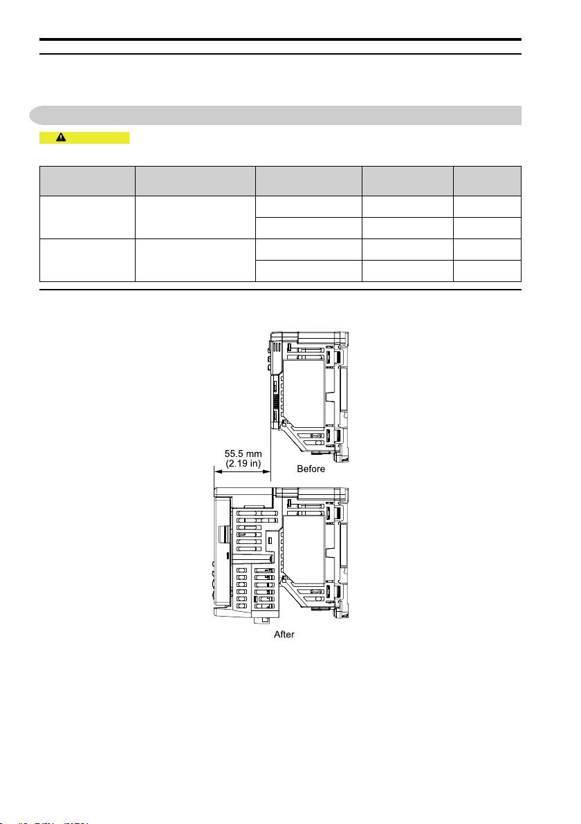
Installation
Orientation
Install the drive vertically or horizontally for sufficient airflow to cool the drive.
Refer to the drive Technical Manual for more information.
NOTICE Do not put drive peripheral devices, transformers, or other electronics near the drive.
Shield the drive from electrical interference if components must be near the drive. Components near the drive can
cause incorrect drive operation from electrical interference.
NOTICE Do not let unwanted objects, for example metal shavings or wire clippings, fall into the
drive during drive installation. Put a temporary cover over the drive during installation. Remove the temporary
cover before start-up. Unwanted objects inside of the drive can cause damage to the drive.
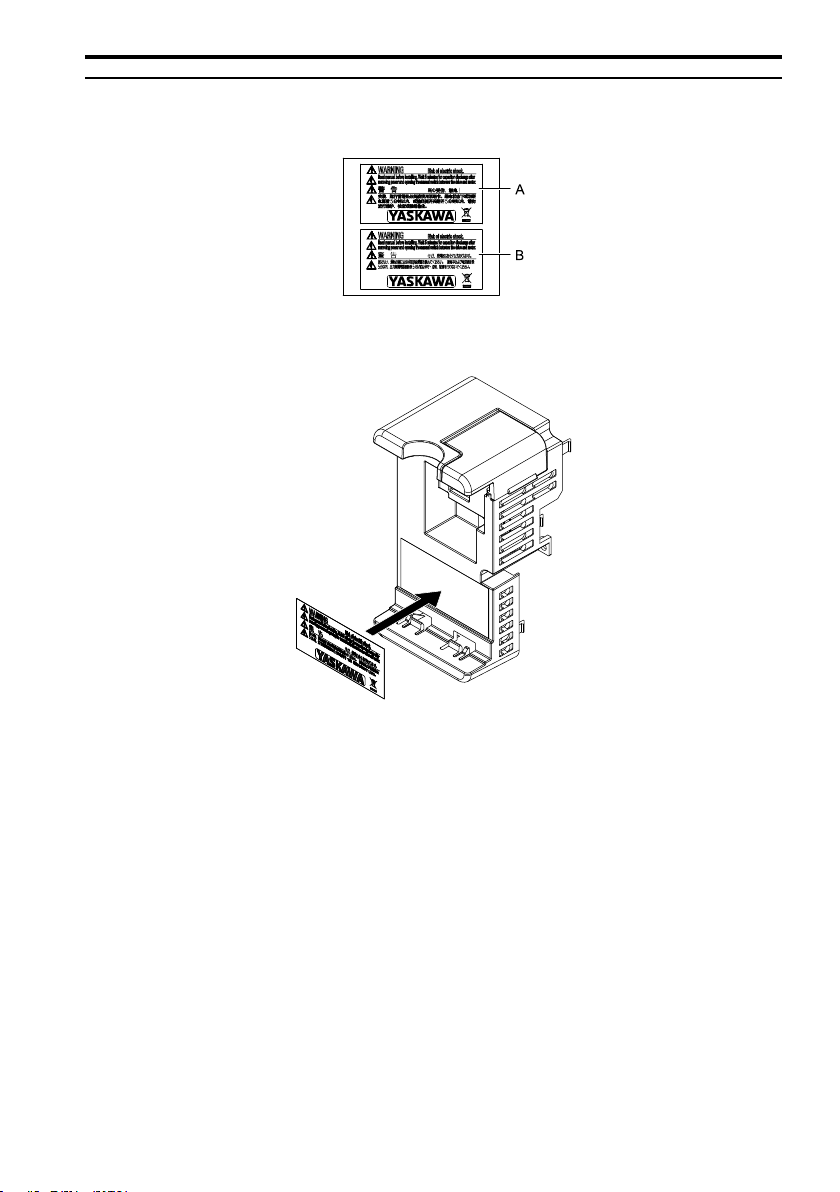
4 Receiving
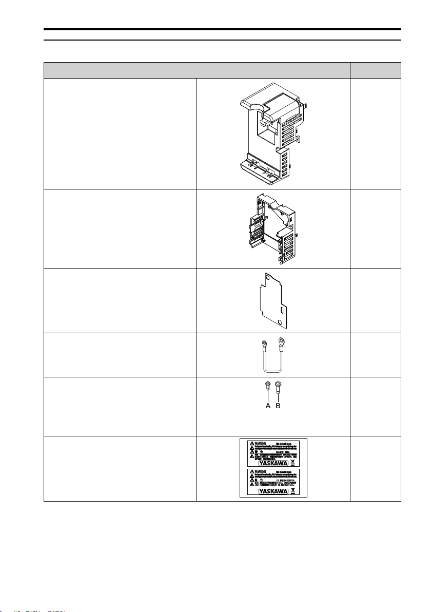
1. Examine the products for damage.
If there is damage to the products, contact the shipping company immediately. The
Yaskawa warranty does not include damage from shipping.
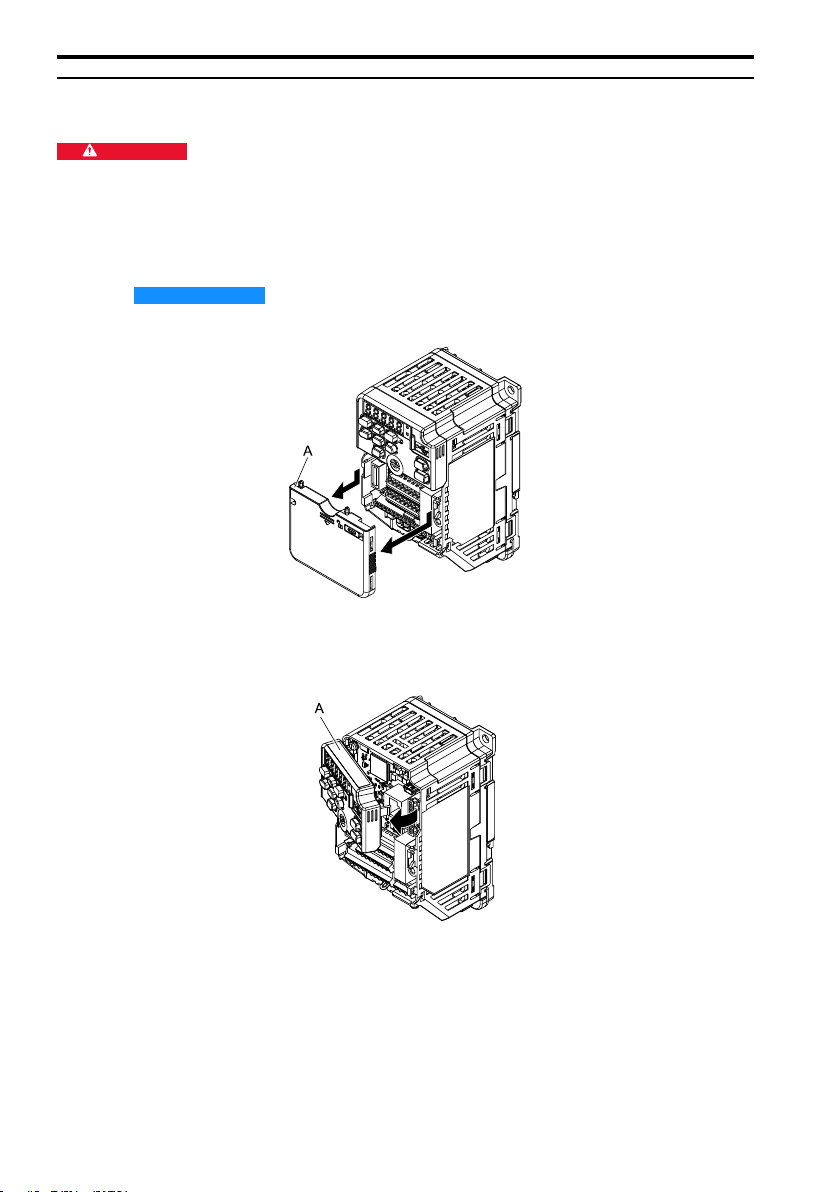
2. Verify the product model number to make sure that you received the correct model.
If you have problems with the products, contact the distributor where you purchased the
products or the Yaskawa sales office immediately.

4 Receiving
YASKAWA TOEP C720600 05B LCD Keypad Attachment Installation Manual 7
◆Option Package Contents
Parts Qty
Bracket #1
Base #1
Insulator *1 #1
Ground Wire #4
Mounting Screw
A - 3 × 8 tapping screw
B - 4 × 12 tapping screw
A - #2
B - #1
Warning Label #1
*1 Use the insulator when you install a communication option (sold separately).
Note:
1. When you install a communication option, use the LED label included with the option.
2. The ground wires and screws included with the communication option are not necessary.

5 Installation Procedure
8YASKAWA TOEP C720600 05B LCD Keypad Attachment Installation Manual
◆Necessary Tools
To install the attachment, use Phillips screwdriver #2.
5 Installation Procedure
CAUTION Crush Hazard. Tighten terminal cover screws and hold the case safely when you move the
drive. If the drive or covers fall, it can cause moderate injury.
Drive Model Enclosure Protection
Design
Communication
Option Procedure Ref.
GA50xxxxxxB IP20/UL Open Type
No A 10
Yes B 13
GA50xxxxxxF IP20/UL Type1
No A 10
Yes C 18
◆Option Dimensions
The installed option adds 55.5 mm (2.19 in) to the total depth of the drive.
Figure 5.1 Option Dimensions

5 Installation Procedure
YASKAWA TOEP C720600 05B LCD Keypad Attachment Installation Manual 9
◆Put the Warning Label on the Bracket
When you use the drive in Japan or China, you must put the correct warning label on the
bracket.
A - For China (written in both English and
Chinese)
B - For Japan (written in both English and
Japanese)
Put the warning label over the existing warning label.

5 Installation Procedure
10 YASKAWA TOEP C720600 05B LCD Keypad Attachment Installation Manual
◆Install the Attachment (Procedure A)
De-energize the drive before you start the procedure.
DANGER Electrical Shock Hazard. Do not examine, connect, or disconnect wiring on an energized
drive. Before servicing, disconnect all power to the equipment and wait for the time specified on the warning label
at a minimum. The internal capacitor stays charged after the drive is de-energized. The charge indicator LED
extinguishes when the DC bus voltage decreases below 50 Vdc. When all indicators are OFF, measure for
dangerous voltages to make sure that the drive is safe. If you do work on the drive when it is energized, it will
cause serious injury or death from electrical shock.
1. Remove the front cover from the drive.
NOTICE Damage to Equipment. When you touch the option, make sure that you
observe correct electrostatic discharge (ESD) procedures. If you do not follow procedures, it can
cause ESD damage to the drive circuitry.
A - Front cover
Figure 5.2 Remove the Front Cover
2. Remove the LED keypad.
A - LED Keypad
Figure 5.3 Remove the LED Keypad
3. Install the base to the drive.
Push the base until the hooks click into place on the drive.

5 Installation Procedure
YASKAWA TOEP C720600 05B LCD Keypad Attachment Installation Manual 11
A - Base
Figure 5.4 Install the Base
4. Install the bracket to the drive.
Note:
The insulator is not necessary.
Push the bracket until the hooks click into place on the drive and use the supplied screw
B to safety the bracket.
Tighten the screws to a correct tightening torque:
• 4 ×12 tapping screw: 0.69 N∙m to 0.73 N∙m (6.11 in∙lb to 6.46 in∙lb)

5 Installation Procedure
YASKAWA TOEP C720600 05B LCD Keypad Attachment Installation Manual 13
◆Install the Attachment (Procedure B)
De-energize the drive before you start the procedure.
DANGER Electrical Shock Hazard. Do not examine, connect, or disconnect wiring on an energized
drive. Before servicing, disconnect all power to the equipment and wait for the time specified on the warning label
at a minimum. The internal capacitor stays charged after the drive is de-energized. The charge indicator LED
extinguishes when the DC bus voltage decreases below 50 Vdc. When all indicators are OFF, measure for
dangerous voltages to make sure that the drive is safe. If you do work on the drive when it is energized, it will
cause serious injury or death from electrical shock.
1. Remove the front cover from the drive.
NOTICE Damage to Equipment. When you touch the option, make sure that you
observe correct electrostatic discharge (ESD) procedures. If you do not follow procedures, it can
cause ESD damage to the drive circuitry.
A - Front cover
Figure 5.7 Remove the Front Cover
2. Remove the LED keypad.
A - LED Keypad
Figure 5.8 Remove the LED Keypad
3. Connect the ground wire included with attachment to the drive ground terminal.
Connect the drive side of the ground wire to the drive ground terminal.

5 Installation Procedure
14 YASKAWA TOEP C720600 05B LCD Keypad Attachment Installation Manual
Note:
Four different ground wires are packaged with the option. The length and the terminal size on the drive side of
the ground wire are different for different drives. Use the correct ground wire for your drive. Refer to Table 5.1
for ground wire selection.
A - Communication option side of the
ground wire
B - Drive side of the ground wire
C - Ground terminal
D - Ground wire
Figure 5.9 Connect the Ground Wire
Table 5.1 Ground Wire Length
Drive Model Length
mm
Three-Phase 200 V
Class
Single-Phase 200 V
Class
Three-Phase 400 V
Class
- - - 150
2001, 2002, 2004, 2006,
2008, 2010, 2012, 2018,
2021
B001, B002, B004,
B006, B010, B012, B018
4001, 4002, 4004, 4005,
4007, 4009, 4012 200
2030, 2042 - 4018, 4023 250
2056, 2070, 2082 - 4031, 4038, 4044, 4060 400
4. Use the supplied screw A to attach a communication option and an Insulator to the
base.
Tighten the screws to a correct tightening torque:
• 3 ×8 tapping screw: 0.49 N∙m to 0.73 N∙m (4.34 in∙lb to 6.46 in∙lb)
A - Base
B - Insulator
C - Communication option
D - Screw A
Figure 5.10 Install the Communication Option

5 Installation Procedure
YASKAWA TOEP C720600 05B LCD Keypad Attachment Installation Manual 15
5. Install the base to the drive.
Push the base until the hooks click into place on the drive.
A - Base
Figure 5.11 Install the Base
6. Use the supplied screw A to connect the option side of the ground wire to the
communication option.
Tighten the screws to a correct tightening torque:
• 3 ×8 tapping screw: 0.49 N∙m to 0.73 N∙m (4.34 in∙lb to 6.46 in∙lb)

5 Installation Procedure
16 YASKAWA TOEP C720600 05B LCD Keypad Attachment Installation Manual
A - Ground wire B - Screw A
Figure 5.12 Connect the Ground Wire
7. Connect communication cables to an option connector.
Isolate communication cables from main circuit wiring and other electrical lines. Refer to
the instruction manual for each communication option for more information.
8. Put the communication option LED label on the bracket.
A - Bracket B - LED label
Figure 5.13 Put the LED Label on the Cover
9. Install the bracket to the drive.
Push the bracket until the hooks click into place on the drive and use the supplied screw
B to safety the bracket.

5 Installation Procedure
YASKAWA TOEP C720600 05B LCD Keypad Attachment Installation Manual 17
Tighten the screws to a correct tightening torque:
• 4 ×12 tapping screw: 0.69 N∙m to 0.73 N∙m (6.11 in∙lb to 8.67 in∙lb)
A - Bracket B - Screw B
Figure 5.14 Install the Bracket
10. Put the keypad into the bracket.
A - Keypad
Figure 5.15 Attach the Keypad

5 Installation Procedure
18 YASKAWA TOEP C720600 05B LCD Keypad Attachment Installation Manual
11. Set the drive-related parameters.
Refer to the instruction manual for each communication option for more information.
◆Install the Kit (Procedure C)
De-energize the drive before you start the procedure.
DANGER Electrical Shock Hazard. Do not examine, connect, or disconnect wiring on an energized
drive. Before servicing, disconnect all power to the equipment and wait for the time specified on the warning label
at a minimum. The internal capacitor stays charged after the drive is de-energized. The charge indicator LED
extinguishes when the DC bus voltage decreases below 50 Vdc. When all indicators are OFF, measure for
dangerous voltages to make sure that the drive is safe. If you do work on the drive when it is energized, it will
cause serious injury or death from electrical shock.
1. Remove the top protective cover and the front cover from the drive.
NOTICE Damage to Equipment. When you touch the option, make sure that you
observe correct electrostatic discharge (ESD) procedures. If you do not follow procedures, it can
cause ESD damage to the drive circuitry.
A - Top protective cover B - Front cover
Figure 5.16 Remove the Top Protective Cove and the Front Cover

5 Installation Procedure
YASKAWA TOEP C720600 05B LCD Keypad Attachment Installation Manual 19
2. Remove the LED keypad.
A - LED Keypad
Figure 5.17 Remove the LED Keypad
3. Remove the screw that attaches the front cover of the conduit.
Figure 5.18 Remove the Screw that Attaches the Front Cover of the Conduit.
4. Connect the supplied ground wire to the drive conduit bracket.
Use the screw that attaches the conduit bracket to connect the drive side of the ground
wire to the drive conduit bracket.
Tighten the screws to a correct tightening torque:
• M4 ×10 truss head screws: 0.98 N∙m to 1.33 N∙m (8.67 in∙lb to 11.77 in∙lb)
Note:
There are four different ground wires in the option package. The length and the terminal size on the drive side
of the ground wire are different for different drives. Use the correct ground wire for your drive.

5 Installation Procedure
20 YASKAWA TOEP C720600 05B LCD Keypad Attachment Installation Manual
A - Communication option side of the
ground wire
B - Drive side of the ground wire
C - Ground terminal
D - Ground wire
Figure 5.19 Connect the Ground Wire
5. Use the supplied screw A to attach a communication option and insulator to the base.
Tighten the screws to a correct tightening torque:
• 3 ×8 tapping screw: 0.49 N∙m to 0.73 N∙m (4.34 in∙lb to 6.46 in∙lb)
A - Base
B - Insulator
C - Communication option
D - Screw A
Figure 5.20 Install the Communication Option
6. Install the base to the drive.
Push the base until the hooks click into place on the drive.
Table of contents
Other YASKAWA Keypad manuals

YASKAWA
YASKAWA JVOP-KPLCC04A Series User manual

YASKAWA
YASKAWA JVOP-KPLCB04AxB User manual

YASKAWA
YASKAWA 900-239-230-001 User manual

YASKAWA
YASKAWA JVOP-KPLCD04AxB User manual

YASKAWA
YASKAWA JVOP-180 User manual

YASKAWA
YASKAWA JVOP-KPLCC04A Series User manual

YASKAWA
YASKAWA JVOP-KPLCA04A Series User manual

YASKAWA
YASKAWA JVOP-KPLEA04A Series User manual
Popular Keypad manuals by other brands

Paradox
Paradox Digiplex EVO DGP2-641BL Reference and installation manual

Paradox
Paradox Digiplex User quick reference guide

Contro l4
Contro l4 C4-KC120277 Series installation guide

Resolution
Resolution RE352 manual

Paradox
Paradox Esprit 639 installation manual

Black Box
Black Box ControlBridge CB-KEYPAD-208-T user manual