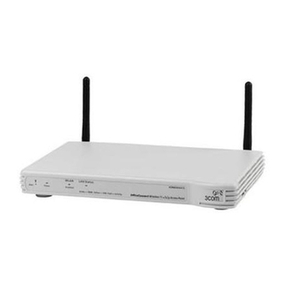
Trycom Technology TRP-C34M User manual

TRP-C34M
User’s Manual
4-Port Modbus TCP to RTU/ASCII Gateway with 3KV Optical
Isolation
User’s Manual
Printed May 2019 Rev 1.0
Trycom Technology Co.,Ltd
No.35, Zhongxing Rd., Guishan Township, Taoyuan County 333, Taiwan.
Tel : 886-3-350-3351 Fax: 886-3-350-3352
Web: www.trycom.com.tw
Copyright
Copyright Notice: The information in this manual is subject to change without notice to improve reliability, design and
function and does not represent a commitment on the part manufacturer. No part of this manual may be reproduced,
copied, or transmitted in any form, without prior written permission by the manufacturer. Products mentioned in this
manual are mentioned for identification purposes only. In this manual, product names appearing may or may not be
registered trademarks of their respective companies or copyright.

2
1. Introduction
TRP-C34M is a 4-Port Modbus gateway.
There are two functions below:
Modbus RTU/ASCII serial master to Modbus TCP slave bi-diction.
Modbus TCP master to Modbus RTU/ASCII slave bi-direction.
The TRP-C34M is able to run under industrial environment stable, it provides 3KV optical
isolated protection between Ethernet interface and 4-port serial interface.
The TRP-C34M provides a watchdog timer function that allows the system to automatically
recover from a system crash. When the TRP-C34M microprocessor stop working correctly, the
watchdog timer waits for a preset period of time and performs a hardware reset.
1-1 Features
Wide input range DC power supply.
Provide 3KV optical isolation protection.
Supports Ethernet Mode like TCP Server, TCP Client, and UDP.
Support Auto-MDIX twisted pair crossover detection and auto-correction.
Maximum allowed bandwidth is 921 Kbps per Serial Port.
Supports PPPoE , DDNS , NTP , FTP , Telnet.
Runs in Stand Alone Mode.
Built in Restore Factory default push button.
Auto direction RS485 flow control by hardware.
Power/Link and 4 pairs serial RX/TX mode LED indicator.
Support screw terminal and standard external DC power adaptor.
Panel mounts support.
1-2 Specification
CPU:32 bit 580MHZ with MMU.
Power Input Voltage: DC +9V to +24V.
LAN: Auto-MDIX, 10/100 Mbps Auto-detecting.
RS-232: TX, RX, GND.
RS-422: TX+, TX-, RX+, RX-.
RS-485: Data +, Data –.
Data Rate: 300,600,2400,4800,9600,19200,38400,57600,115200,230400,460800 and
921600 bps.
Parity: none, even, odd.
Data Bits: 5, 6, 7 or 8.
Stop Bits: 1, 2.
Configuration through Windows Admin Utility / Web Console / Telnet Console.
Protocol: ARP,IP, ICMP,UDP,TCP,HTTP,DHCP,PPPoE,DDNS ,NTP,FTP,Telnet.

3
Power supply: Screw terminal, or standard external DC adapter.
Serial interface: +/-15 KV ESD.
RS422/485 interface: Surge, over current, over voltage protection.
Serial terminal and Ethernet with 3KV Optical Isolation.
Power consumption: 12V/400 mA .
Operating Temperature: -20 °C to 65 °C.
Humidity: 0~90% Non-Condensing.
Dimensions: 180(L)*110(W)*30(H) /mm.
Weight: 400g (W/Packing).
2. Hardware Description
The following information is provided to give the user an understanding of how to connect the
TRP-C34M to the LAN and serial device. A review of the switch settings and the functionality of
the LED’s are also provided.
2-1. Panel layout
2-2. LED indicator
PWR:Power LED keep on when the DC input.
SYS: The system boot time needs 36sec after SYS LED will blinking, it means that the device is
working.

4
TX/RX LED: COMA~COMD Transiting/Receiving Indicator.
2-3. Power Input
DC Jack: Power Input DC +10V to +24V. (Please use the 5.5*2.1mm DC JACK).
There are two types power input.
a. Use the plug of power adaptor than plug in the DC jack on the side.
This approach also allows the user to provide additional power to other devices using the
terminal from EU regulation.
b .Wiring terminals on the EU regulation
2-4. RST button
Keeping pushes the RST button over 10-sec when power on, and the SYS and WiFi LEDs will
blinking then TRP-C34M will be back to factory default setting.
3. Install TRP-C34M Hardware
STEP1: Please connect the power source, the PWR LED will on and wait the SYS LED will
blink.
STEP2: Connect TRP-C34M with internet port by RJ45 LAN cable.
*The TRP-C34M Support Auto-MDIX, A straight-through or crossover Ethernet
cable can be used to make a connection directly to the HUB/Router/PC.
STEP3: Connect TRP-C34M with RS232, RS422 or RS485 with Modbus RTU or ASCII
protocol.
3-1. RS485 Wiring
3-2. RS422 Wiring

5
3-3. RS232 Wiring
The RS-232 supports 2 channels plus Signal Ground and is configured as DTE like a computer.
Signals are single ended and referenced to Ground.
*Please try to connect pin1,4,6 and Pin 7,8 together if RS232 device does not work.
4. How to configure TRP-C34M
There are 2 ways to access the Server Properties and program the TRP-C34M.
a. Using the IoT Device Finder utility.

6
b. Using the WEB Server

7
4-1. Using IoT Device Finder utility.
The “IoT Device Finder” utility performs several functions:
A: Searching for TRP-C34M connected to the network.
B: Displaying and changing the configuration of TRP-C34M.
C: Upgrading the TRP-C34M firmware.
D: Save, reboot and back factory settings.
4-2. Searching LAN for TRP-C34M
Once TRP-C34M is connected to the LAN the IoT Device Finder utility will search it and display
it in a window by name, IP address, Mac….Information, please click the “Find” button to looking
for that.
The IoTdevice Finder utility will find the TRP-C34M.
* Please make sure the PC’s network IP 3 segment as same as TRP-C34M.
Such as PC’s network IP should set up 192.168.1.xx ,and the TRP-C34M’s default IP is
192.168.1.100.

8
4-3.Configuring Server Properties
Click the GoTo button, when the login prompt appears, login using the administrator and
password. Click Log In.
the factory default setting below:
User Name: admin
Password: admin
Please click the “Log In” button after you completed the User Name and Password.

9
4-4.System web UI:
Admin Password:
Maximum 25 chars.
Confirm Password:
Input the password again.
Auto Reset (Minutes):
Sets the amount of time a user can remain idle before being reset.
Device Name:
Device server name.
Device Description:
Device is described.
System Up time:
Device power on time.
Firmware Release:
Firmware Release time.

10
4-5.Network web UI:
Wireless:
Option, it should be disabled.
Ethernet:
Static Mode:
Selecting Static IP requires the user to assign the IP information for the device manually.
*Please make sure your host pc the network segment as same as this IP.
Such as: PC:192.168.1.xx, and the device is 192.168.1.100.
DHCP Mode:
Selecting this mode will cause the device to obtain an IP address from the local DHCP server.
IP Address: The Gateway IP address.
Mask
The default LAN Netmask is configured for a Class C address. This may be reconfigured by the
user.
DNS
Short for Domain Name System, an Internet service that translates domain names into IP
addresses. Because domain names are alphabetic, they're easier to remember. The Internet
however, is really based on IP addresses. Every time you use a domain name, therefore, a DNS
service must translate the name into the corresponding IP address.

11
4-6.Serial web UI:
From Serial1,Serial2,Serial3 to Serial4.
Baud Rate:
From 300,600,2400,4800,9600,19200,38400,57600,115200,230400,460800 and 921600 bps.
Parity:None,Even,Odd.
Data Bits:5,6,7,8
Stop Bits:1,2
Flow Control:None,XON/XOFF.
RxDelay(ms):0
TxDelay(ms):0

12
4-7.Gateway web UI:
From Gate1, Gate2, Gate3 and Gateway4.
Gateway Type:
There are 4-port, each port can set up different connect type independently below:.
a.RTU To TCP Slave.
b.ASCII To TCP Slave.
c.TCP To RTU Slave.
d.TCP To ASCII Slave.
e.DISABLED.
Default Listen port:501,502,503,504.

13
If User chooses the RTU to TCP Slave or ASCII type, the Gateway web UI will appear the
screen below:
ID Range(1~255) Using UID range to map a query from Modbus serial master with an UID
within this range to an IP and port.
Each port can up to 8 sets Modbus slave TCP.

14
5. Application Multi-Function Application

15
5-1.Modbus TCP to RTU/ASCII Application
Example:
Step1.Perform this utility, and input IP/Port, click the OK button, then Select function code, the
response will appear below:
*the Modscan32 utility copyright belong the Win-TECH Software Design, user can find it
from the www.win-tech.com.
Step2. Selecting the function code.

16
Step 3.the utility will appear screen below:
5-2 Modbus TCP Slave to Serial Master
Example:
Step1: Connect Serial Master PC-----RS232-----TRP-C34M-----Ethernet---Multi TCP Slave PC.
Step2: Selecting the RTU to TCP Slave, and input the IP in order to match each Modbus TCP
slave.

17
Step3: Perform the Modbus Poll utility from serial master PC.
*The Modbus Poll and Modbus Slave utility copyright belong the Witte Communications
Company Design; user can find it from the www.modbustools.com.
Step4: Run Modbus Slave utility from TCP Slave PC and setting the function code as same as

18
the Modbus slave poll.
6. Appendix
What is different between TRP-C34R and TRP-C34M
The TRP-C34R RS232/422/485 is Serial Device Server, it can send the data between the TCP
and Serial port bi-direction, it cannot process the data or convert the Modbus protocol.
TRP-C34M is Modbus TCP Gateway
As a Modbus TCP to RTU/ASCII slave device server.
The TRP-C34M is able to analyze Modbus protocols and auto to convert between Modbus
TCP and Modbus RTU/ASCII.
As Serial Modbus master (PLC) to Modbus TCP slave.
The TRP-C34M is able to analyze the protocol from Serial Master then send them to every
Modbus TCP slave devices.
Table of contents
Other Trycom Technology Gateway manuals
