Page 8of 15
3.5 Connection of external reader and/or extension module
PR311SE controller is equipped with built-in reader for EM 125kHz (UNIQUE) proximity cards and
can operate with additional external reader of PRT series and/or XM-2 extension module. The
address of external reader must be ID=0 (factory default address of PRT reader) and the address
of XM-2 must be ID=5. Both mentioned device should be connected to CLK and DTA wires. Any
type of cables (e.g. unshielded twisted pair) can be used for CLK and DTA lines. The guaranteed
communication distance is 150 meters.
Note: Practically, devices communicating in RACS Clock&Data standard (e.g. PRT readers) can be
connected to the controller for distances up to 500m, but it is not guaranteed by the manufacturer.
3.6 Input and output lines
The functions are assigned to input and outputs by means of PR Master software or by means of
commands entered with controller keypad or external reader keypad (e.g. PRT12LT). Default
function for REL1 relay output is door unlock.
3.6.1 Inputs
All inputs (IN1-IN3) of PR311SE have identical electric structure and can be configured as NO or NC
lines. The NO input is triggered by shorting it to supply minus (GND) while the NC input must be
normally shorted to supply minus (GND) and it becomes triggered when connection with ground is
discontinued. Every input is internally connected to the power supply (+12V) through 15kΩ resistor.
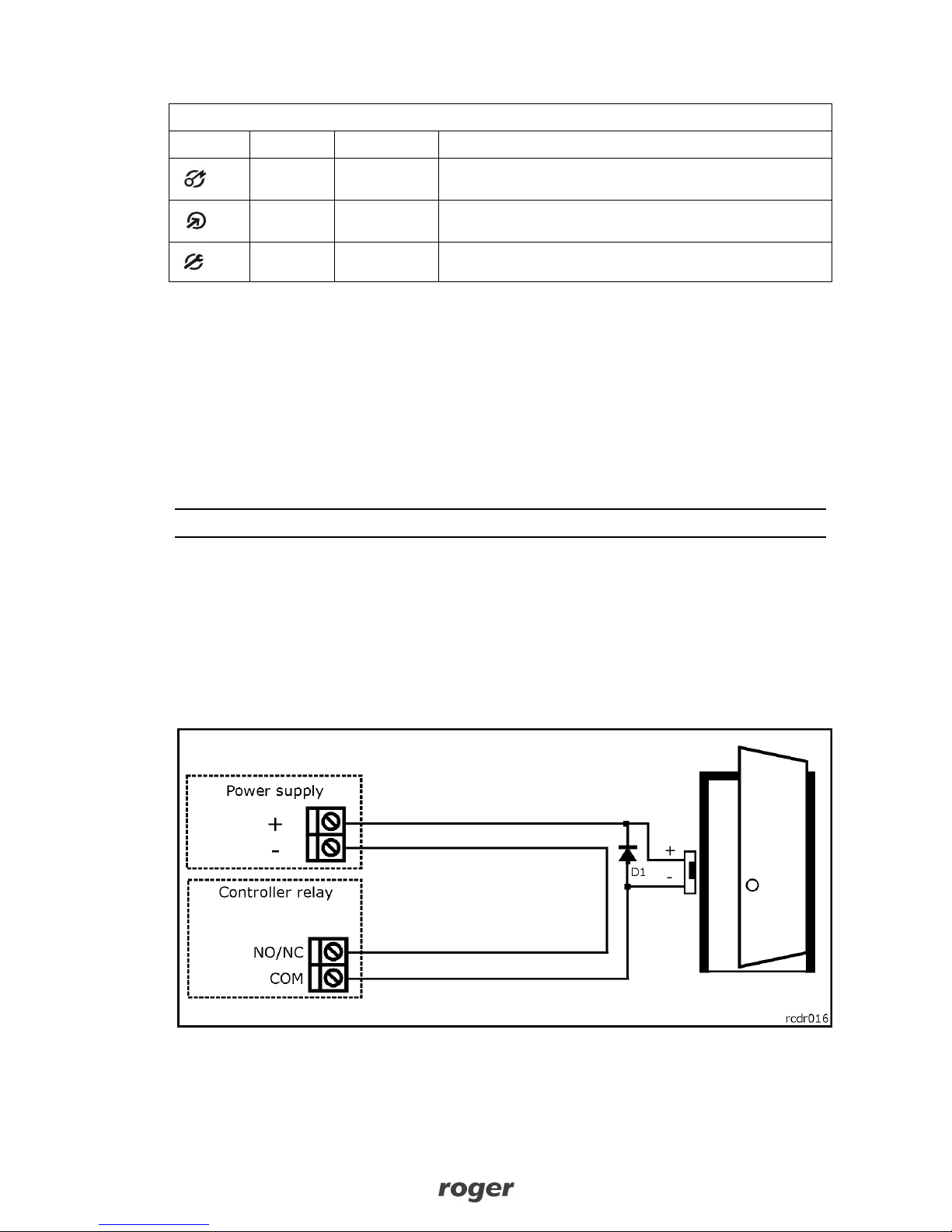
3.6.2 Relay outputs
The relay output REL1 offers one switched contact rated 30V/1.5A. The relay contacts are internally
protected against overvoltage by semiconductor elements. However this does not release the
installer from responsibility to eliminate interferences from inductive elements by an additional
diode. It is forbidden to use relay output to switch voltages above 30V because this for sure will
cause damage to the semiconductor elements protecting the relay’s contacts. In the normal state
(the relay is off) the NC-COM contacts are shorted. In the triggering state (the relay is on) the NO-
COM contacts are shorted. In case of lack of the power, the REL1 output is in the off state.
3.6.3 General purpose outputs
Two transistor outputs (IO1, IO2) are available in PR311SE controller. All these lines are open
collector type, i.e. in the normal (off) state are pulled to supply plus via 15kΩ resistor and when on,
they short to supply minus. Both lines can switch current up to 1A DC while voltage connected to
the output must not exceed 15VDC. In case of overcurrent state, transistor outputs are
automatically switched off and the controller automatically restarts.
3.7 RS485 communication bus
The RS485 bus consists of two signal lines A and B. In the RACS 4 system any topology can be
used (star, tree or any combination of them, except for loop) in order to connect controllers in
subsystem and to establish access control system. The matching resistors (terminators) connected
at the ends of transmitting lines are not required. In most cases communication works with any
cable type (standard telephone cable, shielded or unshielded twisted pair etc.) but the
recommended cable is unshielded, twisted pair (UTP). Shielded cables should be limited to
installations subject to strong electromagnetic interferences. The RS485 communication standard
used in the RACS 4 system guarantees proper communication in a distance of up to 1200 meters as
well as high resistance to interferences. UT-4DR communication interface can be used for
communication of computer and PR Master software with remote (above 1200m) RACS 4 network
(subsystem) of controllers. UT-4DR enables the communication through LAN/WAN.
3.8 Controller mounting
PR311SE enclosure consists of front panel and base. New device is assembled with standard base,
but additional, extended base in included. The extended base can be used when connection cable
must be hidden and no flush mounting box is available. Reference dimensions of PR311SE
controller are shown in fig. 3 and fig. 4.