Trynex International SnowEx SP-125 Owner's manual

GR4 — 1© Trynex International 2009 (REV 004) L1188
SP-125 / US-100
SP-225 / US-200
Madison Heights, Michigan 48071
800-725-8377
www.snowexproducts.com

L1188 © Trynex International 2009
Have a question or need assistance?
SnowEx Customer Service
(800) 725-8377
or (586) 756-6555
Monday through Friday 8:00 AM to 4:30 PM EST
Fax: (586) 427-0552
E-Mail: [email protected]
Website: www.snowexproducts.com
GR4 — 2
Table of Contents
INTRODUCTION. . . . . . . . . . . . . . . . . . . . . . . . . . . . . . . . . . . . . . . . . . . . . . . . . . . . . . . . . . . . . . . . . . . . . . . . . . . . . . . . . . . . . . . . . . . . . . 3
GENERAL INFORMATION AND REGISTRATION . . . . . . . . . . . . . . . . . . . . . . . . . . . . . . . . . . . . . . . . . . . . . . . . . . . . . . . . . . . . . . . . . 4
SAFETY . . . . . . . . . . . . . . . . . . . . . . . . . . . . . . . . . . . . . . . . . . . . . . . . . . . . . . . . . . . . . . . . . . . . . . . . . . . . . . . . . . . . . . . . . . . . . . . . . . . .
5-6
•PREPARATION
•OPERATIONS
•SERVICE
SPREADER PARTS/DIAGRAMS. . . . . . . . . . . . . . . . . . . . . . . . . . . . . . . . . . . . . . . . . . . . . . . . . . . . . . . . . . . . . . . . . . . . . . . . . . . . . . 7-12
•SP-125 / US-100 ACCURATE FLOW
•SP-125 / US-100 ACCURATE FLOW COMPLETE DRIVE ASSEMBLY
•SP-225 / US-200 MULTI-PURPOSE
•SP-225 / US-200 MULTI-PURPOSE COMPLETE DRIVE ASSEMBLY
13-14
WIRING INSTRUCTIONS / VAR-020 CONTROL . . . . . . . . . . . . . . . . . . . . . . . . . . . . . . . . . . . . . . . . . . . . . . . . . . . . . . . . . . . . . .
•WIRING DIAGRAM
OPERATING THE SPREADER . . . . . . . . . . . . . . . . . . . . . . . . . . . . . . . . . . . . . . . . . . . . . . . . . . . . . . . . . . . . . . . . . . . . . . . . . . . . . . . . . 21
BLANK PAGE . . . . . . . . . . . . . . . . . . . . . . . . . . . . . . . . . . . . . . . . . . . . . . . . . . . . . . . . . . . . . . . . . . . . . . . . . . . . . . . . . . . . . . . . . . . . . . . 22
SPREADER MAINTENANCE . . . . . . . . . . . . . . . . . . . . . . . . . . . . . . . . . . . . . . . . . . . . . . . . . . . . . . . . . . . . . . . . . . . . . . . . . . . . . . . . . .
23
TROUBLESHOOTING . . . . . . . . . . . . . . . . . . . . . . . . . . . . . . . . . . . . . . . . . . . . . . . . . . . . . . . . . . . . . . . . . . . . . . . . . . . . . . . . . . . . . . . . . . . . . 24-25
WARRANTY . . . . . .. . . . . . . . . . . . . . . . . . . . . . . . . . . . . . . . . . . . . . . . . . . . . . . . . . . . . . . . . . . . . . . . . . . . . . . . . . . . . . . . . . . . . . . .
26-27
SPREADER MOUNT PARTS/DIAGRAMS . . . . . . . . . . . . . . . . . . . . . . . . . . . . . . . . . . . . . . . . . . . . . . . . . . . . . . . . . . . . . . . . . . . 15-20
•PIVOT PAL HITCH MOUNT
•3-POINT MOUNT
•TRAILER MOUNT
•DROP UTILITY MOUNT
•UTILITY MOUNT
•VAR-020 CONTROL

© Trynex International 2009 L1188 GR4 — 3
Introduction
This manual has been designed for your help. It will assist you and instruct you on the proper set-up, installation and use of
this spreader. Refer to the table of contents for an outline of this manual.
We require that you read and understand the contents of this manual completely (especially all safety information) before
attempting any procedure contained herein. Extra copies of Owner/Operator Manuals can be purchased at your Snowex Dealer.
THIS SIGN SHOULD ALERT YOU:
The Society of Automotive Engineers has adopted this SAFETY ALERT SYMBOL to pinpoint characteristics
that, if NOT carefully followed, can create a safety hazard. When you see this symbol in this manual or on the
machine itself, BE ALERT! Your personal safety and the safety of others is involved
.
Defined below are the SAFETY ALERT messages and how they will appear in this manual:
(RED)
Information that, if not carefully followed,
can cause death!
(ORANGE)
Information that, if not carefully followed,
can cause serious personal injury or death!
(YELLOW)
Information that, if not carefully followed,
can cause minor injury or damage to equipment.

L1188 © Trynex International 2009
GR4 — 4
General Information
CONGRATULATIONS!
The spreader you have purchased is an example of snow and ice control technology at its finest! Your spreader’s self-contained
design is a trademark of all Snowex products. Here’s why...
SIMPLICITY: Fewer moving parts manufactured of higher quality means minimal maintenance for your SnowEx spreader.
RELIABILITY:
High impact linear low density polyethelyne hopper, state-of-the-art electronic dual variable speed control, custom engineered
powder coated frame, maximum torque 12 volt motor coupled to a custom engineered transmission found only on SnowEx products.
VERSATILITY:
Multi-use capabilities allows spreading of a variety of materials for snow and ice control.
WARRANTY:
Best in the industry, hands down! 2 years standard and now 5 year extended (optional).
The benefits you are about to recognize are that of time, money and effort.
We welcome you to the world of Snowex Performance.
Registration
Record the following information in this manual for quick reference.
Spreader Model Number _____________________________________________________________________________________
Spreader Serial Number________________________________ Controller Serial Number _______________________________
Date of Purchase___________________________________________________________________________________________
Dealer Where Purchased _____________________________________________________________________________________
When ordering parts, the above information is necessary. This will help to insure
that you receive the correct parts.
At the right is a diagram of the ID tag. This tag on the spreader is located
on the frame.
Please fill out the warranty card with all the necessary information to validate it. This will also give us a record so that
any safety or service information can be communicated to you.

© Trynex International 2009 L1188 GR4 — 5
Before attempting any procedure in this book, these safety instructions must be read and understood by all workers who
have any part in the preparation or use of this equipment.
For your safety ,warning and information decals have been placed on this product to remind the operator of safety precautions.
If anything happens to mark or destroy the decals, please request new ones from Snowex.
Remember, most accidents are preventable and caused by human error. Exercising of care and
precautions must be observed to prevent the possibility of injury to operator or others!
Never operate equipment when under the influence of alcohol, drugs, or medication that might
alter your judgment and/or reaction time.
.riahdeniartsernudnagnihtolcgnittifesoolllaeruces,redaerpsehthtiwgnikrowerofeB
dluocsihtodoteruliaF.latemtsniagalatemgnikrownehwsdleihsedishtiwsessalgytefasraewsyawlA
result in serious injury to the eyes.
Never allow children to operate or climb on equipment.
Never weld or grind on equipment without having a fire extinguisher available.
Always check areas to be spread to be sure no hazardous conditions or substances are in the area.
Always inspect unit for defects: broken, worn or bent parts, weakened areas on spreader or mount.
Always shut off vehicle and power source before attempting to attach or detach or service spreader
unit. Be sure vehicle/power source is properly braked or chocked.
Always make sure personnel are clear of areas of danger when using equipment.
Always keep hands, feet, and clothing away from power-driven parts.
Remember, it is the owner’s responsibility to communicate information on safe usage and proper
maintenance of all equipment.
Safety

L1188 © Trynex International 2009
GR4 — 6
Safety
Never exceed 45 m.p.h. when loaded spreader is attached to vehicle. Braking distances may be
increased and handling characteristics may be impaired at speeds above 45 m.p.h.
Never use wet materials, or materials with foreign debris with any of these spreaders. These units are
designed to handle dry, clean, free-flowing material. Note: Can not spread water softener salt.
Never leave material in hopper for long periods of time. Be aware that all ice melters are hygroscopic
and will attract atmospheric moisture and harden up.
Always inspect pins and latches whenever attaching or detaching spreader, and before traveling.
Inspect the unit periodically for defects. Parts that are broken, missing, or worn out must be replaced
immediately. The unit or any part of it can not be altered without prior written permission from the
manufacturer.
D 6546
D 6548
D 6335
D 6544
D 6545
D 6547
Examples of warning decals to indicate operational awareness.

Parts Breakdown
Model #SP-125 / US-100
© Trynex International 2009 L1302 GR4-7
Key Part No.
D4318 WASHER, 3/8 X 1-1/2"
D6133 BOLT, 5/16-18 X 1/2"
D6138 NUT, 5/16-18
T15018 NUT, 5/16-18 NYLOX WAXED
D6166 BOLT, 5/16-18 X 1"
D6705 GATE SLIDE
D6302 KNOB, 5/16-18 X 3/4"
D6304 CABLE, T-HANDLE 10'
D6305 BULKHEAD CABLE FITTING
D6308 BOLT, 5/16-18 X 3/4" HEX HEAD, W/ HOLE
Description Qty.
4
2
14
1
2
1
1
1
1
1
D6462 BOLT, 5/16-18 X 1-3/4"
D6703 GATE STOP INDICATOR
12
1
Key Part No. Description 1
D6704 GATE TRACK 1
D6705 GATE SLIDE
D6706 GATE DECK
D6753 HOPPER, 3.0 CU. FT. FLAT
D6712 HOPPER SUPPORT TUBE
D7172 NUT, 3/8-24 HEX JAM
D7173 LOCK WASHER, 3/8 INTERNAL
1
1
1
1
1
1
D6165 WASHER, 5/16 2

L1188 © Trynex International 2009
GR4 — 8
Assembly Instructions
Model #SP-125 / US-100 (refer to diagram on page GR4-7)
Step 1: Attach hopper tube support (D 6712) to complete drive assembly using (4) 5/16"-18 x 1-3/4" hex bolt (D 6462)
and (4) 5/16" lock nut (D 6138). Use holes at bottom end of tube.
Step 2: Place spreader gate deck (D 6706) upside down on table.
Step 3: Assemble gate indicator/stop (D 6703) on stop slide with gate knob (D6302). Gate stop must be on the
inside of deck where it will stop the track.
Step 4: Insert (1) 5/16 bolt with hole (D 6308)
(D 6308) on bolt
through gate slide (D 6705) . Finger tighten (1) 5/16" locknut (D 6138)
Step 5: Take bulkhead cable fitting (D 6505) and screw it onto T-handle cable - 10' (D 6304) rubber coating.
Step 6: Place assembly through tab on gate deck. Tighten down with supplied washer and nuts. Note: There should be
a nut on either side of tab.
Step 7: Lower gate assembly over spinner shaft. Spinner shaft must go through 5/8" hole on deck.
Step 8: Fasten deck to hopper tube using (4) 5/16" hex bolts (D 6462) and (4) 5/16" locknuts (D 6138) NOTE: You
must first tighten bottom bolts, pull front of deck up, then tighten top set of bolts.
Step 9: Place hopper (D 6753) on deck. 5/8” hole must be used for spinner shaft.
Step 10: Finger tighten (2) 5/16 x 1" bolts (D 6166) through bottom of hopper.
Step 11: Place (4) at washers (D 4318) over hex bolts (D6462). Place bolts through hopper back and in though tube
support. Tighten with (4) 5/16" locknuts.
Step 12: Tighten bolts in bottom of hopper.
Step 13: Place agitator (D 6405) on spinner shaft. Tighen to middle of at with short allen key.
Step 14: Attach receiver mount (D 6485) to transmission weldment (D 6480) using (4) 1/2" hex bolts (D 4116) and (4) 1/2" lock
nuts (D 4120).
Gate Cable Installation
Step 1: Place unit on vehicle where it will be permanently used. Place hitch pin in hitch so unit does not move.
Step 2: Route T-handle to desired operating location. There cannot be any bends or sharp corners.
Step 3: Take T-handle out of sleeve. Take nuts and washer o of sleeve.
Step 4: Drill hole to mount T-handle. Screw (1) supplied nut and washer on cable after inserting through drilled hole.
Step 5: Close gate slide all the way.
Step 6: Re-insert cable handle and wire all the way. Aim through bolt with hole and tighten bolt.

© Trynex International 2009 L1188 GR4 — 9
Complete Drive Assembly Parts Breakdown
Model #SP-125/US-100
Key Part No. Description Qty.
D 4135 2-5/16" Hair Pin Clip 1
D 4136 5/8" x 5-1/2" Hitch Pin 1
D 6131 1/4"-20 x 1/2" Serr. Flange Bolt 4
D 6746 5/16'' x 1-1/4 Detent Clevis 1
D 6172 #10-32 x 5/8" Serr Flange Bolt 2
D 6140 5/16" - 18 x 3/8" S.S. Set Screw 1
D 6750 10" Plastic Spinner 1
D 6232 Motor Drive Coupler 1
r 1otatigA5046D
D 6410 Motor 12 Volt DC 1
D 6487 #8 x 1/2" Hex Head Sheet Screw 5
D 6715 Transmission 14.5 to 1 1
D 7153 Plastic Bottom Cover 1
D 6480 Transmission Weldment 1
D 6485 Light Duty Receiver Mount 1
D 4116 1/2"-13 x 1-1/2" Hex Bolt 4
D 4120 1/2" Lock Nut 4
D 6782 Complete Drive Assembly

L1188 © Trynex International 2009
GR4 — 10
Parts Breakdown
Model #SP-225 / US-200
.ytQnoitpircseD.oNtraPyeK
D 4318 3/8" Fender Washer 4
t 12unkcoL"61/58316D
D 6462 5/16" - 18 x 1-3/4" HHCS 12
154 2.7 cu/ft Salter Hopper Yellow76D
1kceDtaorhTretlaS2076D
D 6712 Hopper Tube Support 1
D 6783 CompleteDriveAssembly 1

© Trynex International 2009 L1188 GR4 — 11
Assembly Instructions
Model #SP-225 / US-200 (refer to diagram on page GR4-10)
Step 1: Attach hopper tube support (D 6712) to complete drive assembly using (4) 5/16"-18 x 1-3/4" hex bolt
(D6462) and (4) 5/16” locknut (D6138) . Use holes at bottom end of tube.
Step 2: Take auger (D 6122) and set on table to tap (1) cap (D 6191) into tube between auger uprights.
Step 3: Place auger on shaft of transmission and tighten to top of at with (1) set screw (D 6140).
Step 4: Place salter throat deck (D 6702) over auger and between hopper tubing support.
Step 5: Using (4) 5/16"-18 x 1-3/4" bolts (D 6462) and (4) 5/16" locknuts (D 6138) , hand tighten through
upper set of holes on tube support.
Step 6: With 1/2" wrench and socket, tighten bottom set of bolts on throat deck.
Step 7: Lift up on throat deck at the front (auger hole side) to level deck. Tighten top set of bolts.
Step 8: Place hopper throat (D 6754) through deck around auger. Line up with holes in tube support.
Step 9: Place 3/8" fender washer (D 4318) on (4) 5/16" hex bolts (D 6462) . Insert through hopper, through tube
and secure with 5/16" nut on back of unit. Tighten.
Step 14: Attach receiver mount (D 6485) to transmission weldment (D 6480) using (4) 1/2" hex bolts (D 4116)
and (4) 1/2” lock nuts.
Step 8: Insert receiver tube end into Receiver Hitch and secure with pin (D 4136).
Step 9: Wire spreader according to wiring instructions.

L1188 © Trynex International 2009
GR4 — 12
Complete Drive Assembly Parts Breakdown
Model #SP-225 / US-200
Key Part No. Description Qty.
D 4135 2-5/16" Hair Pin Clip 1
D 4136 5/8" x 5-1/2" Hitch Pin 1
D 6131 1/4"-20 x 1/2" Serr Flange Bolt 4
D 6746 5/16'' x 1/4” Detent Clevis Pin 1
D 6172 #10-32 x 5/8’’ Serr Flange Bolt 2
D 6140 5/16" - 18 x 3/8" S.S. Set Screw 1
D 6750 10" Plastic Spinner 1
D 6232 Motor Drive Coupler 1
r 1eguA2216D
D 6410 Motor 12 Volt DC 1
D 6487 #8 x 1/2" Hex Head Sheet Screw 5
D 6715 Transmission 14.5 to 1 1
D 7153 Plastic Bottom Cover 1
D 6480 Transmission Weldment 1
D 6485 Light Duty Receiver Mount 1
D 4116 1/2"-13 x 1-1/2" Hex Bolt 4
D 4120 1/2" Lock Nut 4
Complete Drive Assembly
D 6783

© Trynex International 2009 L1188 GR4 — 13
SP-125 / SP-225 / US-100/ US-200 Wiring Instructions
Step 1: First, install switch at desired location.
Step 2: Run spreader/vehicle harness from the rear of vehicle to switch area. Attach the female spade red wire to the switch.
Leave the black wire for Step 5.
Step 3: Route the power harness from the battery to the switch/control.
Step 4: Attach the red lead to the positive side of the battery and the black lead to the negative side of the battery.
Step 5: Attach the female spade red wire on switch terminal. Using 3" double female black wire jumper attach the black
wire from the power harness to the black wire of the vehicle harness.
Step 6: Install rubber weatherproof boot on switch before finishing installation.
Step 7: Insert dielectric grease on terminals of SAE plug at rear of vehicle.
Wiring Diagram
Model #SP-125/SP-225/US-100/US-200
25
AMP
BATTERY
REMOVE JUMPER FOR USE
WITH VAR-020 VARIABLE
SPEED CONTROLLER KIT
DOUBLE FEMALE
3" JUMPER
Key Part No. Description Qty.
D 6184 On/Off Switch 1
D 6406 Rubber Switch Boot 1
D 6719 Wiring Harness 1
D 6425 Fuse Holder 1
D 6748 25 Amp Breaker 1
D 7105 3/8" Ring Terminal 2
IMPORTANT: In the off season remove control
and put in a cool dry place. The interior summer
temperatures could damage circuit board and
void warranty.

© Trynex International 2009 L1188
GR4 — 14
Variable Speed Control (Optional Kit)
Model # VAR-020
Key Part No. Description Qty.
D 6474 Mini Control 1
D 6486 325 Harness 1
D 6748 25 Amp Breaker 1
25 AMP
(+) Pos.Red
(–) Neg. Black
(–) Neg. Black
(+) Pos.Red
12 VOLT
BATTERY
On/Off Switch
Speed Control Knob
SPREADER MOTOR
IMPORTANT: In the off season remove control
and put in a cool dry place. The interior summer
temperatures could damage circuit board and
void warranty.

© Trynex International 2009 L1188 GR4 — 15
Utility Mount Parts Breakdown
Model #UTM-175 / FLM-175
Spreader
(reference only)
Maximum Load Weight
Not To Exceed 240 lbs. Gross
.ytQnoitpircseD.oNtraPyeK
D 4315 Lock Knob Assembly (FLM-175 Only) 2
D 6426 Fork Lift Mount Frame (FLM) 1
D 4116 1/2"-13 x 1 1/2" Hex Bolt 8
8rehsaWtalF"2/19114D
8tuNkcoL"2/10214D
1
r (UTM)evieceRytilitU
8416D
D 6235 Underbody Support Plate 2
&

© Trynex International 2009 L1188
GR4 — 16
Trailer Mount Parts Breakdown
Model #TLR-175
.ytQnoitpircseD.oNtraPyeK
D 4116 1/2'' - 13 x 1-1/2'' Hex bolt 2
2stunkcoL-''2/10214D
3pilcnipriaH5314D
D 4136 5/8'' x 5 -1/2'' Hitch pin 1
1eugnotreliarT8346D
1emarf”A“reliarT9346D
D 6440 Receiver tube mount 1
2eritreliarT1446D
D 6442 5/8'' - 13 x 7'' Hex bolt special 2
D 6443 5/8'' Flat washers 4
MAXIMUM LOAD WEIGHT NOT TO EXCEED 240 LBS. GROSS
TRAILER MOUNT ASSEMBLY INSTRUCTIONS
Step 1: Insert axle through wheel and axle weldment.
Step 2: Put washer on, then install hair pin clip to secure axle. Repeat Steps 1 and 2 for other side.
Step 3: Bolt tube support on axle weldment.
Step 4: Insert trailer tongue per drawing and pin into position.
Step 5: Insert spreader mount into opposite side of trailer tongue and pin into position.

© Trynex International 2009 L1188 GR4 — 17
Three-Point Mount Parts Breakdown
Model #TPM-175
CAUTION: MAXIMUM OF 240 LBS. GROSS WEIGHT CAN BE PUT ONTO MOUNT.
Key Part No. Description Qty.
D 4133 5/16” Linch Pin 2
D 4135 2-5/16” Hairpin Clip 1
D 4136 5/8” x 5-1/2” Hitch Pin 1
D 4137 7/8” x 5-1/2” Lift Arm Pin 2
D 6147 Three Point Frame
1

Pivot Pal Mount Parts Breakdown
Model #PPT-175
© Trynex International 2009 L1188
GR4 — 18
Spreader
(reference only)
PPT-175
Assembled View
Step 1: Assemble spreader swing arm to spreader hitch arm with and & nut and bolt. Do not over tighten since this
may cause the arm to bind and will not swing open freely.
Step 2: Collapseassemblyandinstall hitchpintokeepassemblyfromopening.
Step 3: Remove existing 1/2” bolts from spreader drive assembly and mount spreader assembly to spreader (see illustration).
Re-tighten hardware per illustration.
Step 4: With assitance, lift spreader into position and insert into vehicle receiver mount. Install hitch pin with clip.
Step 5: Remove swing arm hitch pin and swing spreader out
on drivers side, at this time use a spray lubricant such
as automotive lithium type or a grease based product.
This will help prevent unwanted corrosion in the pivot
joint; this should be checked on a regular basis during
the season.
Step 6: Close spreader and re-install hitch pin with clip.
Step 7: Plug spreader into spreader harness and test for
power on.
.ytQnoitpircseD.oNtraPyeK
D 6051 Hitch Arm 1
D 6052 Swing Arm 1
D 4136 Hitch Pin With Clip 2
D 6052 1/2” x 2-1/2” Shoulder Bolt 1
D 4124 3/8”-16 Nylon Hex Nut 1
D 4116 1/2”-13 x 1-1/2” Hex Bolt 4
D 4120 1/2”-13 Lock Nut 4
D 6049 1/2” x 1/6” Bronze Thrust Washer 2

© Trynex International 2009 L1188 GR4 — 19
Drop Utility Mount Parts Breakdown
Model #DRM-175
.ytQnoitpircseD.oNtraPyeK
2rehsaWtalF"2/19114D
2tuNkcoL-"2/10214D
D 4121 3/8"-16x1 Hex Bolt 2
8tuNkcoL-"8/34214D
9rehsaWtalF"8/35214D
D 4135 2 - 5/16" Hair Pin Clip 2
D 4136 5/8" x 5-1/2" Hitch Pin 2
D 6246 1/2" - 13 x 2-1/2" Hex Bolt 2
D 4318 3/8" Fender Washer 8
.ytQnoitpircseD.oNtraPyeK
D 6420 3/8" - 16 x 2 Truss Bolt Full Thread 8
D 6421 3/8" - 16 Hex Nut 2
D 6422 3/8" - 16 x 5" Hex Bolt 1
D 6423 2'' Rubber Stopper 1
2liaRgnitnuoM2346D
D 6434 Drop Mount Weldment 1
D 6435 Mounting Rail Hat Section 2
1retpadAeluM6346D
Maximum Load Weight Not To Exceed 240 lbs. Gross
#3 & #17 Form Stop Type One
#11, 5, 13 & 12 Form Stop Type Two

© Trynex International 2009 L1188
GR4 — 20
Drop Utility Mount Installation Instructions
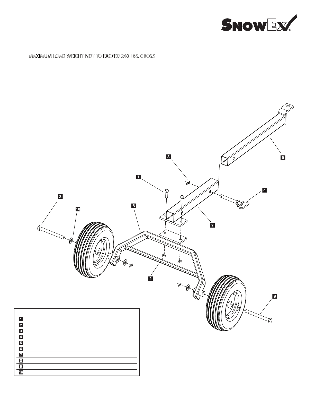
CAUTION: MAXIMUM WEIGHT NOT TO EXCEED 240 LBS.
MULE 550
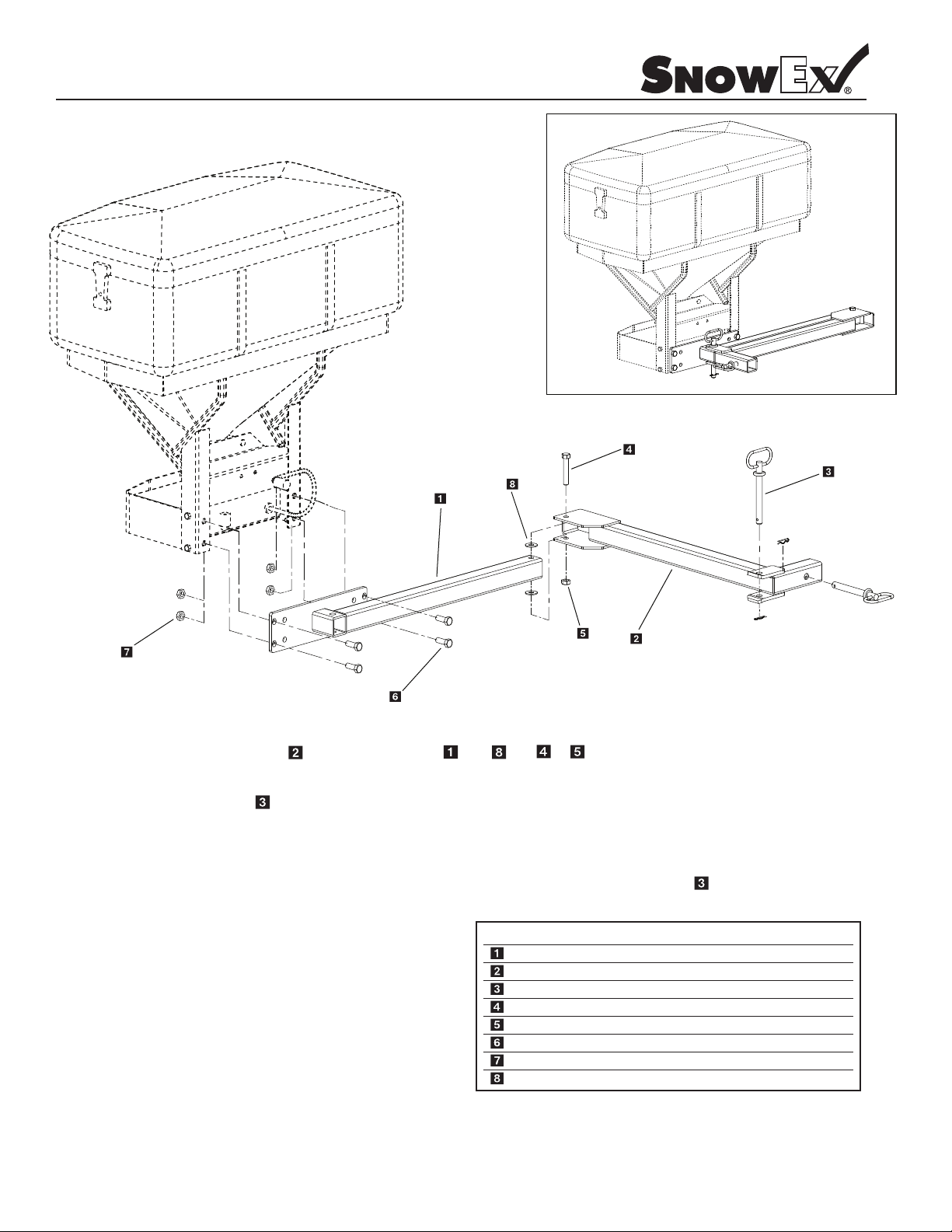
Step 1: Temporarily remove the tailgate. Remove the bed liner if equipped.
Step 2: Bolt support rails to spreader mount with 1/2” bolts. Install 1/2” hex bolt with washer through rail first then
spreader mount. Install 1/2” locknut and tighten. Avaid over tightening to avoid potentially crushing tube.
Step 3: Place spreader mounting rails over spreader mount support rails and install pins. Locate the spreader bracket
mounting rails on top of the bed by centering left to right and positioning the rear edge of the rails 5/8” beyond the
rear of the bed. Transfer mounting holes to bed and drill 7/16” holes.
Important: Check for proper clearance underneath bed before drilling holes.
Step 4: Bolt rails under belt with truss head bolts, fender washers, SAE washers and nylock nuts. Install the spreader
Step 5: Install 550 anti dump bracket with (2) 3/8” bolts provided.
Step 6: Install gate control cable per attached instructions.
Step 7: Route Cables at your discretion and install switch.
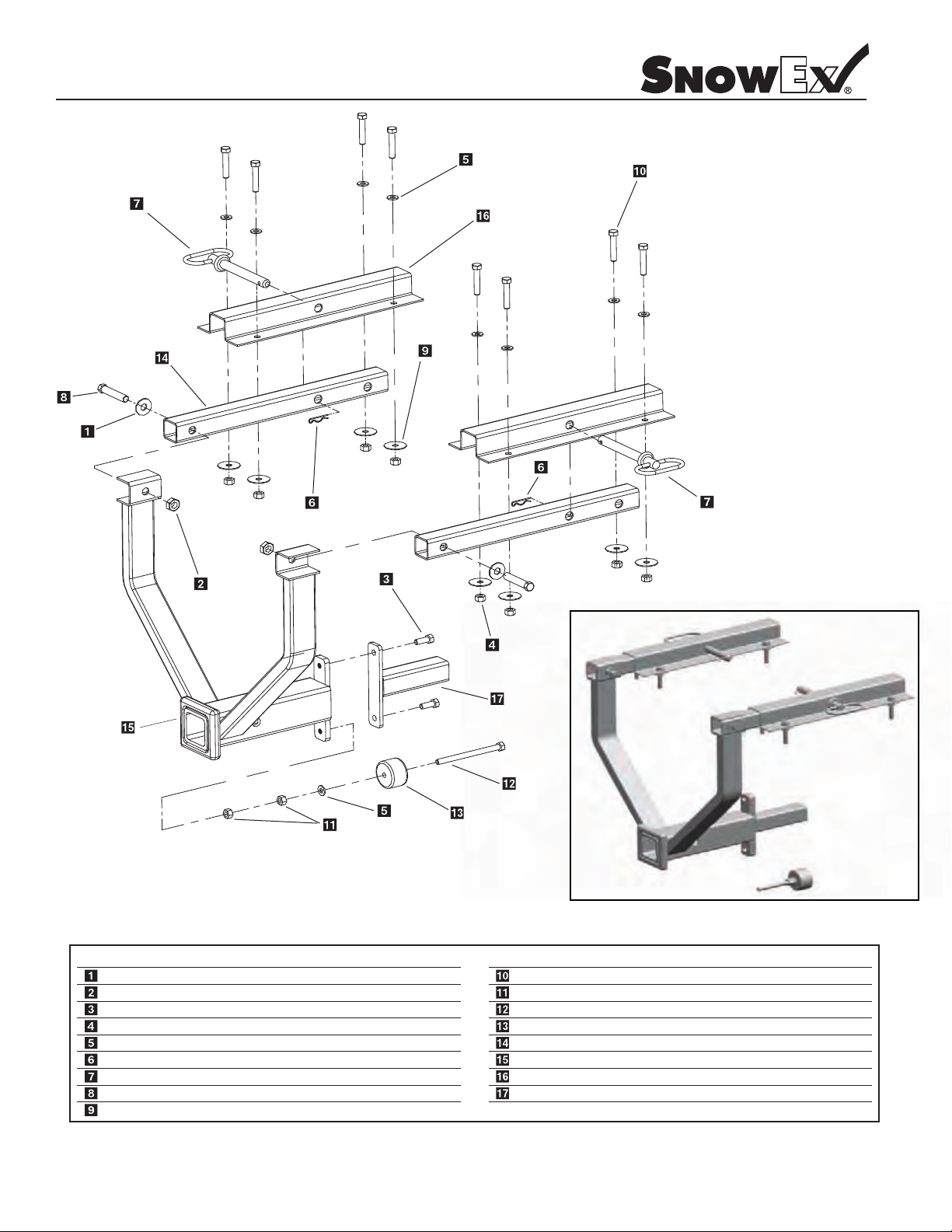
MULE 2500
Step 1: When positioning the mounting rails, the end of the rail should be 1/2” forward of the rear edge of the bed.
Step 2: The universal anti dump threads into the lower weld nut on the spreader bracket assembly. Adjust rubber
CLUB CAR CARRYALL
Step 1: Remove the bed tailgate and bottom angle trim. Also remove the two rear carriage bolts from the floor of the bed.
Step 2: Place spreader mounting rails over spreader mount and install pins.
Step 3: Install truss head bolts, fender washers, SAE washers and nylock nuts in the carriage bolt holes. Transfer the
JOHN DEERE GATOR
Step 1: Remove the bed tailgate.
Step 2: Place spreader mounting rails over spreader mount and install pins.
Step 3: Locate the spreader bracket mounting rails on top of the bed by centering left to right, push main mount flush
Step 4:
Step 5: The universal anti dump threads into the lower weld nut on the spreader bracket assembly. The rubber bumper
bracket before tightening hardware. The tailgate and bed liner may be reinstalled now.
The installation of the spreader on the 2500 is the same as the 550 with the following exceptions.
bumper to be 1/2” to 3/4” behind the rear axle-receiver hitch assembly.
Locate the two front outside mounting rails over the holes from the carriage bolts and remove.
remaining mounting rail holes and bolt rails into bed.
up against rear of bed to locate mounting rails. Transfer mounting holes to bed.
Install truss head bolts, fender washers, SAE washers and nylock nuts in the 1/2” mounting holes.
should be adjusted to rest against the frame of the vehicle. The trailer hitch bracket may need to be relocated
depending on the configuration.
Model # DRM-175
This manual suits for next models
4
Table of contents
Other Trynex International Spreader manuals

Trynex International
Trynex International SnowEx Pro 575X User manual

Trynex International
Trynex International SnowEx Bulk Pro 1875 User manual

Trynex International
Trynex International TurfEx TT5000 User manual

Trynex International
Trynex International SnowEx SL-80 Owner's manual

Trynex International
Trynex International TurfEx TS45 User manual

Trynex International
Trynex International SnowEx V-Maxx 8500 User manual

Trynex International
Trynex International TurfEx RS7200E User manual

Trynex International
Trynex International SnowEx Precision Pro SP-1675 User manual