TSCHAN Nor-Mex FG User manual

TSCHAN GmbH Zweibrücker Straße 104 D-66538 Neunkirchen-Saar
Telefon: +49(0) 6821 866 0 Telefax: +49(0) 6821 883 53 www.tschan.de
BAWN 060-GBR-0
09/2004
Assembly and operating instructions TSCHAN®
Elastic coupling
Nor-Mex®FG

bawn060-gbr-0 Nor-Mex®FG - 2 -
Content
Chapter Page
1 Notes on safety.................................................................................................................2
2 Function............................................................................................................................3
2.1 Appropriate Use.........................................................................................................3
3 Marking of the coupling.....................................................................................................3
4 Storage.............................................................................................................................3
5 Construction .....................................................................................................................4
6 Technical data..................................................................................................................5
7 Assembly..........................................................................................................................6
7.1 Pay attention before the assembly ............................................................................6
7.2 Finished borehole......................................................................................................7
7.3 Installing coupling......................................................................................................7
8 Adjusting coupling ............................................................................................................9
8.1 Angular misalignment..............................................................................................10
8.2 Radial displacement................................................................................................10
8.3 Axial displacement...................................................................................................11
9 Operation........................................................................................................................12
9.1 Sense of rotation test...............................................................................................15
10 Maintenance ..................................................................................................................17
10.1 Inspection and maintenance intervals .....................................................................17
10.2 Wear limit of elastic buffers......................................................................................18
10.3 Changing the elastic intermediate ring ....................................................................19
11 Waste Disposal..............................................................................................................20
12 Manufacturer Declaration...............................................................................................21
1 Notes on safety
The present assembly and operating instruction (AOI) constituents a part of the coupling
supply. Always keep the AOI near the coupling well accessible.
Make sure that all persons charged with the assembly, operating, service, and maintenance
have read and understood the AOI and follow all the points:
- Avert hazards for body and live of the user and third parties.
- Ensure the operating safety of the coupling.
- Avoid the loss of use and environmental impairment through false handling.
In the case of transport, mounting, dismounting and maintenance, attention is to be paid to
the relevant regulations for industrial safety and for environmental care.
The coupling may only be operated, mounted, serviced and maintained by authorised and
trained personnel.
In the interest of further development, we reserve the right to make changes which serve
technological progress.
By the use of accessories and spare parts, which were not originally manufactured by
TSCHAN GmbH, we are not responsible for any resulting damage or liability or guarantee.

bawn060-gbr-0 Nor-Mex®FG - 3 -
2 Function
The coupling Nor-Mex ®-FG is a torsionally elastic and puncture-proof claw coupling.
It balances out angular, radial, and axial shaft misalignments within defined limits. The
coupling transfers the torque via pressure loadable, elastic buffers or Perbunan (Pb) which
are joined together as an intermediate ring.
The elastic intermediate ring can cushion impacts and torsional vibrations; it is oil-tight and
electrically conductive.
A coupling half is divided in two and allows through this a simple separation of the coupled
machine. With the claw ring pulled back it is possible to check the rotational direction of the
drive. It is also possible to lift out radially a coupling half with accompanying aggregate. The
elastic intermediate ring can be changed without axially shifting the machine.
The coupling is usable in every sense of rotation and installation position.
2.1 Appropriate Use
•
• In order to ensure a faultless, lasting operation of the coupling it must be laid out accord-
ing to the layout instructions e.g. DIN 730 part 2 (or also catalogue Nor-Mex ®) with an
operating facture corresponding to the operating conditions.
• Apart from incorporating a finished bore hole with parallel key groove (see “7.2 Finished
borehole”) no further changes can be carried out on the coupling.
• The coupling may only be used within the framework of the conditions defined in the
performance and delivery contract.
• Every change of the conditions of use or the operating parameters necessitates a new
verification of the coupling layout.
3 Marking of the coupling
The product line Nor-Mex ®has its hardness in Shore (A) indicated on the elastic interme-
diate ring.
4 Storage
On receipt of the goods, the supply is to be checked immediately for completeness and
correctness. Possible damages incurred during transit and / or missing parts are to be
notified in writing.
The coupling parts can be stored in their delivered standard-state for 6 months in a dry,
roofed place at normal room temperature. For a longer storage duration a long-term preser-
vation is necessary (consult TSCHAN GmbH). The elastic intermediate ring must not be
subjected to ozone containing mediums, direct solar influence or strong light sources with
ultraviolet-light. The relative humidity should not exceed 65%. In the case of proper storage
the characteristics of the elastic intermediate ring remain unchanged for almost up to three
years.

bawn060-gbr-0 Nor-Mex®FG - 4 -
Bild / Fig. 1 Construction Nor-Mex ® FG
5 Construction
Details:
Claw ring (Pos. 3) and flange hub (Pos. 4) are delivered screwed together.
Balanced parts are position marked to each other.
1 Pan-head screw DIN 912
2 Locking washer (caging-washer)
3 Claw ring part 102…0X3
4 Flange hub part 104
5 Elastic intermediate ring part 010
6 Coupling flange FE/FG part 102…0X4

bawn060-gbr-0 Nor-Mex®FG - 5 -
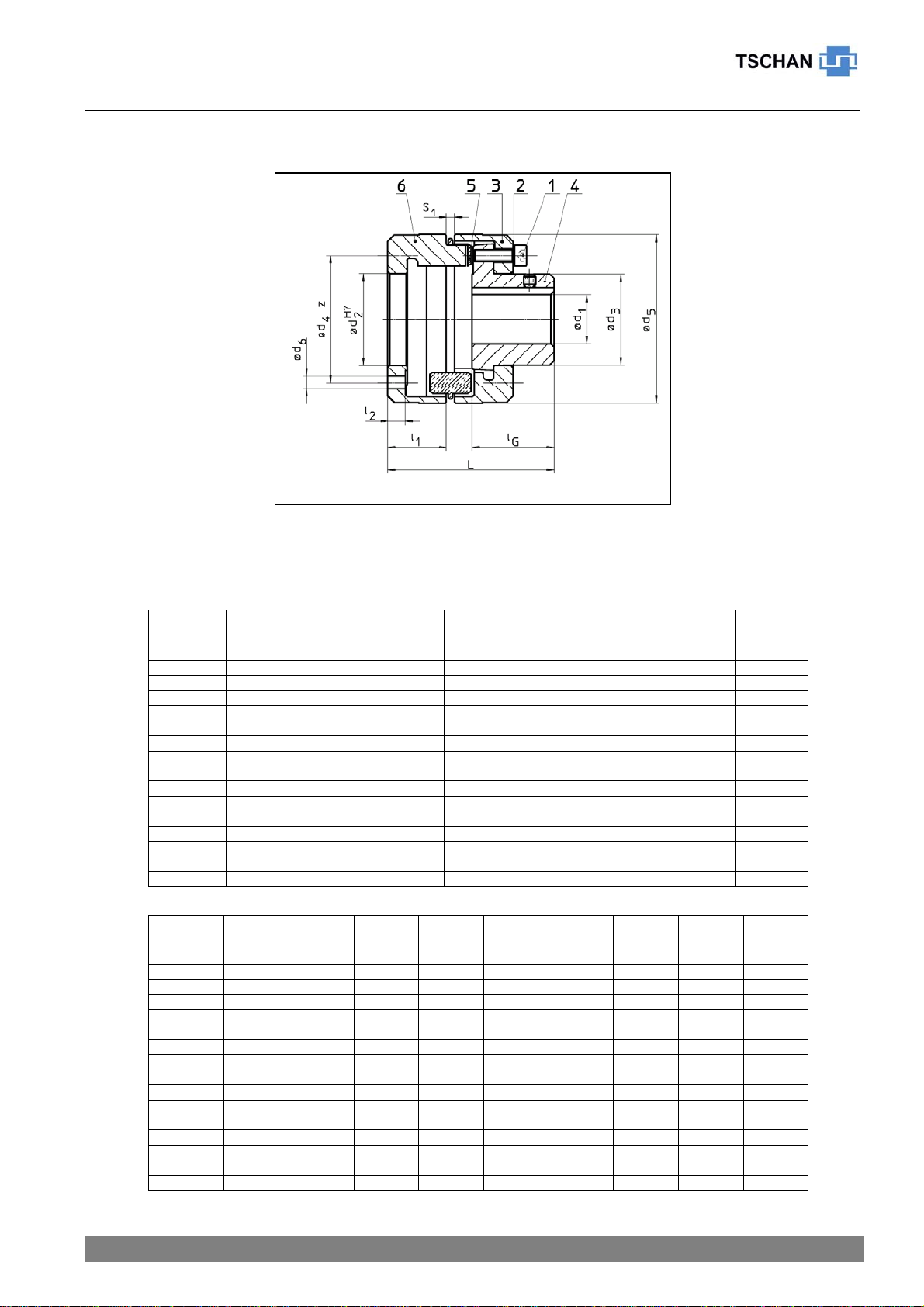
6 Technical data
Table 1 Technical data:
Size
Nor-Mex
FG
TCnom
Pb72
[Nm]
TCpeak
Pb72
[Nm]
TCnom
Pb82
[Nm]
TCpeak
Pb82
[Nm]
nmax
[min-1]
d1
max
[mm]
d2
[mm]
d3
[mm]
82 48 100 75 150 8000 32 45 44,5
97 96 200 150 210 7000 39 55 54,5
112 150 310 230 540 6000 46 65 64,5
128 250 500 380 650 5000 53 75 74,5
148 390 800 600 1350 4500 65 93 92,5
168 630 1300 980 1800 4000 75 105 104,5
194 1050 2000 1650 2400 3500 85 122 121,5
214 1500 3100 2400 4200 3000 95 136 135,5
240 2400 4800 3700 6200 2750 100 147 146,0
265 3700 7500 5800 8300 2500 115 165 164,0
295 4900 10000 7550 10500 2250 130 182 181,0
330 6400 13000 9900 14500 2000 135 209 208,0
370 8900 18200 14000 20000 1750 160 242 241,0
415 13200 27000 20500 27000 1500 180 276 275,0
480 18000 36000 28000 66000 1400 200 290 289,0
Size
Nor-Mex
FG
d4
[mm]
z
quan-
tity
d5
[mm]
d6
[mm]
l1
[mm]
lG
[mm]
L
[mm]
S1
[mm]
m
undrilled
[kg]
82 62 4 82 6,6 28,5 40 80,5 3,0 1,6
97 69 5 97 6,6 29,5 49 92,5 3,0 2,4
112 82 6 112 9,0 37,0 58 110,0 3,5 4,0
128 92 6 128 9,0 38,0 68 122,0 3,5 5,7
148 113 7 148 11,0 45,0 78 141,0 3,5 8,8
168 126 8 168 11,0 51,5 87 153,0 3,5 13,0
194 144 9 194 11,0 57,0 97 178,0 3,5 19,5
214 160 9 214 13,5 62,5 107 195,5 4,0 26,1
240 175 10 240 13,5 66,5 117 213,5 4,0 34,6
265 194 10 265 15,5 76,0 137 246,0 5,5 50,4
295 210 10 295 15,5 80,0 147 264,0 8,0 66,8
330 240 10 330 17,5 86,5 156 282,5 8,0 86,0
370 274 11 370 17,5 94,0 176 313,0 8,0 118,4
415 310 12 415 17,5 102,0 196 343,0 8,0 168,0
480 325 14 480 22,0 108,0 220 373,0 8,0 237,6
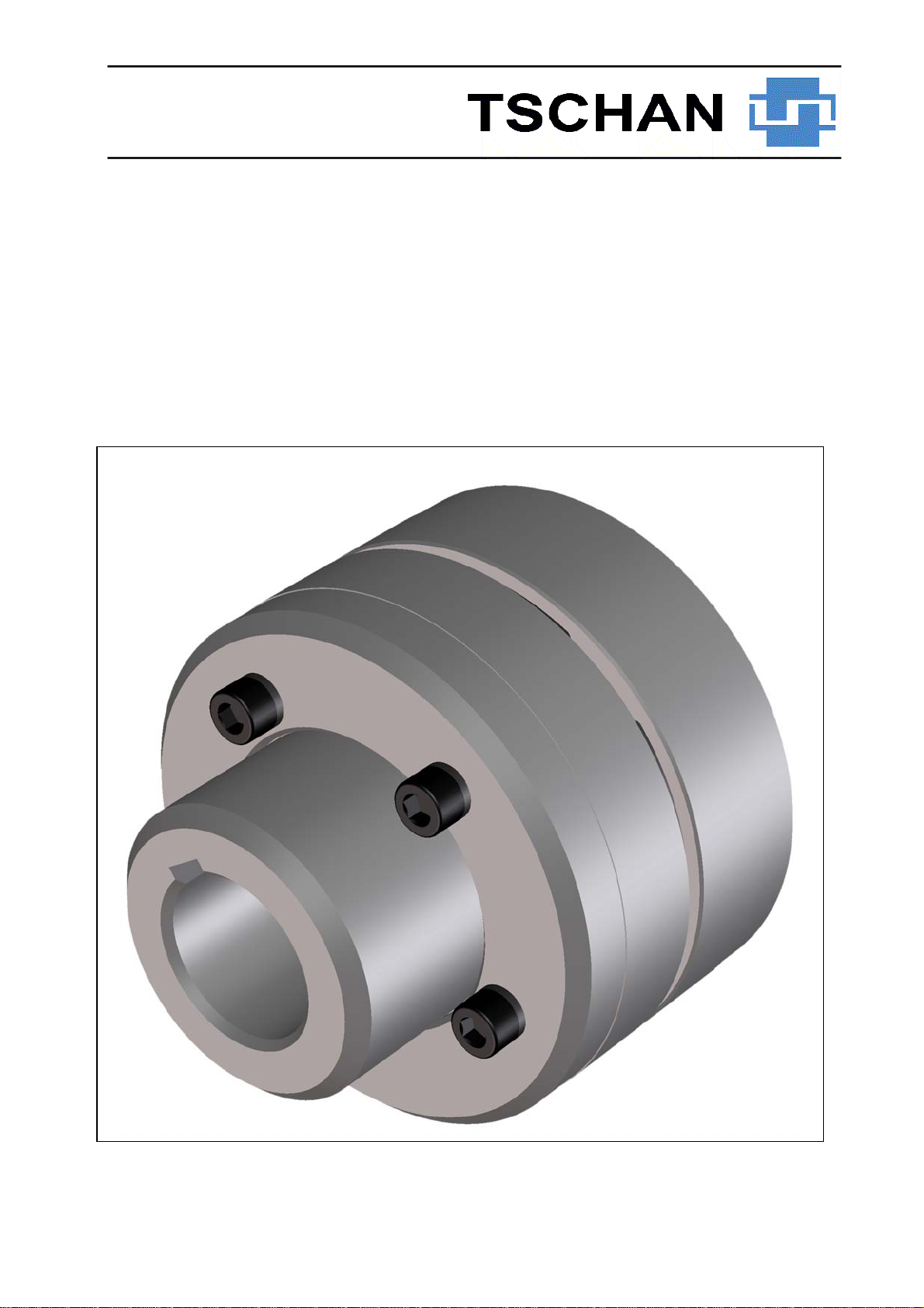
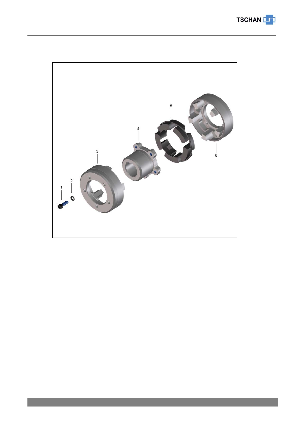
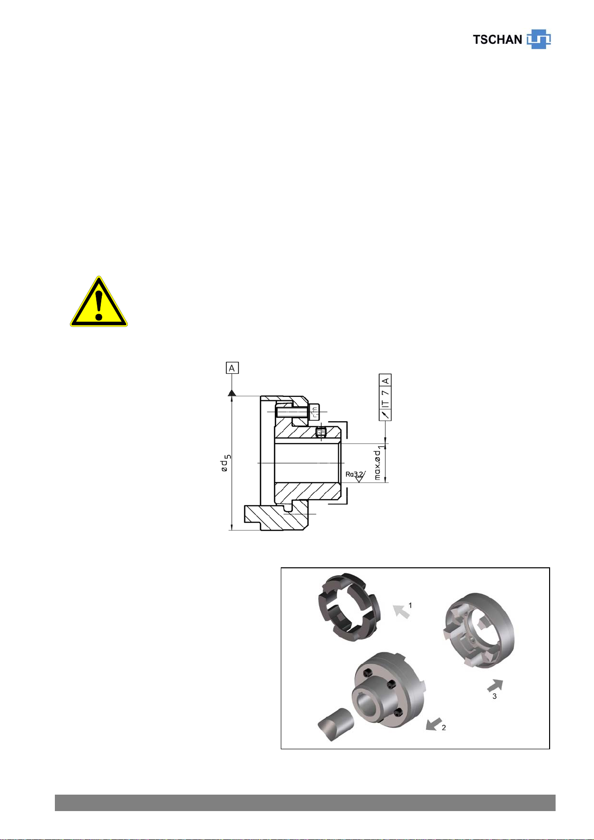
Bild / Fig. 2 Nor-Mex ® FG

bawn060-gbr-0 Nor-Mex®FG - 6 -
The torque TCnom and TCpeak is valid for:
- Intermediate rings of Perbunan Pb72 and/or Pb82,
- Ambient temperatures of -40 °C to +60 °C,
- Operation within the stipulated alignment values.
During the layout of the coupling according to DIN 740 part 2 (or also catalogue Nor-Mex®)
different factors must be considered:
- with higher temperatures a corresponding temperature factor Sυ
- according to the starting frequency a starting factor Sz
- in dependence of the operating conditions an impact factor, SA, SL
With circumferential speeds of more than 22 m/s, we recommend to balance the coupling.
7 Assembly
7.1 Pay attention before the assembly
• Injury hazard!
• Switch-off the drive before all work on the coupling!
• Secure the drive against unintentional switching on and rotating!
• Incorrectly tightened screws can cause serious person injuries and
material damage!
• According to accident prevention rules all freely rotating parts
must be protected through stationary protective devices against
unintentional touching and against falling objects.
• To avoid sparks coverings should be of stainless steel!
• The coverings must fulfil at least the demands of protection type
IP2X.
• The coverings are to be designed in such a way that no dust can
deposit itself on the coupling.
• The covering must not touch the coupling or influence it in its
function.
• Make sure that the intended rotational speeds and torques as well as the ambient tem-
peratures do not exceed the values indicated in “6 Technical Data”.
• The maximum permissible borehole diameter must not be exceeded.
• Check whether the shaft hub connections can safely transmit the occurring operating
torques.
• The standard TSCHAN tolerance for the finished boreholes is fit H7.
• Standard parallel key slot is according to DIN 6885 page 1.
• Check the dimensions and tolerances of shafts, hub boreholes, parallel key and slot.
• Adjust setscrews as required.

bawn060-gbr-0 Nor-Mex®FG - 7 -
Bild / Fig. 3
7.2 Finished borehole
For the completion of the finished borehole in a coupling hub, pay attention to following
procedure:
• Clean the coupling hub of preservatives.
• Tighten the coupling hub to the faces labelled with éand carefully align the coupling hub.
• The indicated values in table 1 for ød1max are valid for a parallel key connection according
to DIN 6885/1 and must not be exceeded.
• Choose the borehole fit so that during the union with the shaft tolerance a wringing fit
and/or an interference fit as for example at H7/m6 is carried out.
• Provide a setscrew for axial securing on the hub back above the parallel key slot.
In the case of other shaft hub connections consultation with TSCHAN GmbH is necessary.
• The maximum indicated borehole diameters are valid for a parallel
key connection according to DIN 6885/1 and must not be exceeded.
• In the case of transgression of these values the coupling can
sever.
• Through flying away fragments danger exists!
7.3 Installing coupling
• Remove the elastic intermediate
ring (Figure 3, pos. 1).
• Clean the borehole of the flange
hub and the shaft end before install-
ing. The surfaces must be clean, dry
and grease-free.
• Use suitable installation aids and
hoists such as cranes or pulley
blocks in the case of bigger cou-
plings.
• Pull the flange hub onto the shaft
end in its intended position (Figure
3, pos. 2).

bawn060-gbr-0 Nor-Mex®FG - 8 -
Bild / Fig. 4
Bild / Fig. 5
Reference:
For easier installation a uniform warming of the hub to 80 °C to 120 °C is safe.
§ Warning!
§ Only work with gloves as a protection against hot parts of the
coupling!
• Mount the hub so that the shaft
ends are flush with the interior
borehole opening (Figure 4).
Pay attention to possible differing
agreements!
• Secure possible available setscrews
by tightening with an adhesive e.g.
Loctite 222 against automatic loos-
ening and flying out.
• Mount the claw ring FE/FG onto the
flange connection. You pay atten-
tion that the parts do not tilt during
the joining onto the centring seat
(Figure 3, pos. 3).
ATTENTION!
The bearing surfaces of the claw ring FE/FG and flange connection must be clean, dry
and grease-free. Balanced parts are position marked to each other.
Let the hot hub cool off to ambient temperature before the introduction of the interme-
diate ring.
• For easier mounting the elastic
intermediate ring can be provided
with a slip additive (e.g. Talcum)
before introduction.
• Fit the intermediate ring into one half
of the coupling
• Push the shaft end with the mounted
coupling half and the claw ring
FE/FG together (Figure 5).
• Adjust the coupling according to the
following specifications in “8 Cou-
pling adjustment”.

bawn060-gbr-0 Nor-Mex®FG - 9 -
8 Adjusting coupling
§ Injury hazard!
§ Switch-off the drive before all work on the coupling!
§ Secure the drive against unintentional switching on and rotating!
§ Reference:
§ An exact alignment of the coupling increases the service life of the
elastic intermediate ring and lessens hazards by use.
§ Do not exceed the maximum permissible displacement values. The
overstepping of these values results in coupling damage and
breakdown!
• When aligning the cold equipment take into account the expected thermal growth of the
components, so that the permissible misalignment values for the coupling are not
exceeded in operation.
• Be aware that the coupling under misalignment imposes restoring forces on the adjacent
shafts and bearings. Take into account that the larger the misalignment, the greater the
restoring forces will be.
• The displacements values indicated in the tables 2 to 4 are maximum permissible guide
numbers.
We recommend not to fully utilise these values during the alignment, so that in operation
sufficient reserves remain for thermal expansions, foundation settlements etc.
• In special cases with high demands on quiet running or high rotating speeds it is possible
that, in the three displacement levels, an alignment accuracy of ≤ 0,1 mm is necessary.
• If the coupling is mounted in a closed housing / casing so that a subsequent alignment is
not possible any more, it must be guaranteed that the geometry and fit accuracy of the
contact surfaces in operation aligns the shafts exactly within the mentioned tolerances.

bawn060-gbr-0 Nor-Mex®FG - 10 -
8.1 Angular misalignment
• Measure on the face of the external
diameter a complete rotation (360°).
Determine in this case the greatest
deviation ∆Kw1 as well as the
smallest deviation ∆Kw2 (Figure 6).
• Calculate the angular misalignment
∆Kw = ∆Kw1 - ∆Kw2.
• The values in table 2 are valid for a
reference rotation speed of
1500 min-1.
Table 2 Maximum permissible displacement values - angular:
Size 82 97 112 128 148 168 194 214 240 265 295 330 370 415 480
∆Kwmax [mm] 0,2 0,2 0,3 0,3 0,3 0,3 0,3 0,3 0,3 0,3 0,3 0,3 0,3 0,3 0,3
8.2 Radial displacement
• Measure a complete rotation (360°).
Determine in this case the greatest
deviation ∆Kr1 as well as the small-
est deviation ∆Kr2 (Figure 7).
• Calculate the radial displacement
∆Kr = 0,5 x (∆Kr1 - ∆Kr2). Pay at-
tention to the operational sign of the
measured values.
• The values of table 3 are valid for a
reference rotation speed of
1500 min-1.
Table 3 Maximum permissible displacement values - radial:
Size 82 97 112 128 148 168 194 214 240 265 295 330 370 415 480
∆Krmax [mm] 0,2 0,2 0,3 0,3 0,3 0,3 0,3 0,3 0,3 0,3 0,3 0,3 0,3 0,3 0,3
Bild / Fig. 6
Bild / Fig. 7

bawn060-gbr-0 Nor-Mex®FG - 11 -
8.3 Axial displacement
• Measure the axial S gap measure-
ment according to figure 8.
• Keep, when aligning the gap
measurement S, to the maximum
permissible tolerance X according to
table 4.
ATTENTION!
If greater axial displacements are
expected in operation, consultation
with TSCHAN GmbH is necessary.
Table 4 Recommended alignment values - axial:
Size 82 97 112 128 148 168 194 214 240 265 295 330 370 415 480
S [mm] 3 3 3,5 3,5 3,5 3,5 3,5 4 4 5,5 8 8 8 8 8
X [mm] ±1 ±1 ±1 ±1 ±1 ±1,5 ±1,5 ±2 ±2 ±2,5 ±2,5 ±2,5 ±2,5 ±2,5 ±2,5
Bild / Fig. 8

bawn060-gbr-0 Nor-Mex®FG - 12 -
9 Operation
When using the coupling attention is to be paid to its characteristics (see „6 Technical data”).
These can in no case be exceeded without having a written agreement from TSCHAN
GmbH.
In order to guarantee a faultless, lasting operation of the coupling, it must be laid out accord-
ing to the regulations e.g. DIN 740 part 2 (or according to catalogue Nor-Mex ®) with an
operating factor corresponding to its operating conditions.
Every change of the conditions of use or the operating parameters makes an inspection of
the coupling layout urgently necessary.
§ Injury danger!
§ Switch-off the drive before all work on the coupling!
§ Secure the drive against unintentional switch-on and rotating!
§ Due to incorrectly tightened screws parts can fly away and cause
serious injuries to persons and damage to material!
§ Check before commissioning the coupling the alignment and all
screw fastenings for their specified tightening torque and/or firm
seating!
§ Before commissioning the plant install all protective devices
against unintentional touching of free moving and/or rotating parts.
§ To avoid sparks coverings in stainless steel should be used!
§ The coverings must fulfil at least the protection type IP2X.
§ The covering is to be so designed that it does not deposit dust onto
the coupling parts.
§ The covering must not touch the coupling or influence it in its
functioning.
Pay attention during the operation of the coupling to:
§ Changed running noises
§ Occurring vibrations
Attention!
• If irregularities are found during operation of the coupling, the drive must be
immediately switched off.
• Detect according to the following table 5, “Operating faults and their possible causes” the
faults and remove.
The listed faults are some examples which are supposed to facilitate fault location.
• For fault finding and elimination all machine components and operating states are
to be considered!

bawn060-gbr-0 Nor-Mex®FG - 13 -
Table 5 Operating faults and their possible causes:
Trouble Cause Risk Warning Correction
Alignment fault Considerable
increase in
coupling tempera-
ture. Premature
wear of elastic
buffers. Increased
reaction forces act
on connected
machines.
- Disconnect drive
- Remove cause for alignment fault
- Re-align coupling
- Inspect elastomer for wear
Elastomer
worn out Coupling claws
strike against
each other. Spark
formation, claw
fracture, in-
creased reaction
forces.
- Disconnect drive
- Check coupling components for
damages and replace parts, if nec-
essary
- Replace elastomer
Unbalance Considerable
increase in
coupling tempera-
ture. Premature
wear of elastic
buffers. Increased
reaction forces act
on connected
machines
- Disconnect drive
- Verify balance state of plant compo-
nents and correct it, if necessary
- Inspect elastomer for wear
Irregular
running
noises/
vibrations
Loose
screw
connec-
tions
Flying off parts
can cause serious
injuries and
considerable
damages.
- Disconnect drive
- Check coupling parts for damages,
replace parts, if necessary
- Verify alignment of coupling
- Tighten screws to the specified
tightening torque and secure them
against working loose, if necessary,
- Inspect elastomer for wear
Premature
wear of
elastomer
Alignment fault Considerable
increase in
coupling tempera-
ture. Increased
reaction forces act
on connected
machines.
- Disconnect drive
- Remove cause for alignment fault
- Re-align coupling
- Inspect elastomer for wear

bawn060-gbr-0 Nor-Mex®FG - 14 -
Trouble Cause Risk Warning Correction
Unaccept-
able
tempera-
tures
Material proper-
ties of elastic
buffers change.
The torque
transmission
capability is
adversely af-
fected.
- Disconnect drive
- Replace elastomer
- Re-align coupling
- Adjust ambient temperature
Contact
with
aggressive
products
Material proper-
ties of elastic
buffers change.
The torque
transmission
capability is
adversely af-
fected.
- Disconnect drive
- Check coupling parts for damages
and replace parts, if necessary
- Replace elastomer
- Verify alignment of coupling
- Prevent contact with aggressive
products
Torsional
vibrations
in the drive
line
Considerable
increase in
coupling tempera-
ture. Premature
wear of elastic
buffers. Increased
reaction forces act
on connected
machines.
- Disconnect drive
- Analyse and eliminate cause for
torsional vibrations
- Check coupling parts for damages
and replace parts, if necessary
- Replace elastomer and consult
TSCHAN GmbH concerning eventual
use of another Shore-hardness
- Verify coupling alignment
Wear limit
of elas-
tomer
exceeded
===>
contact of
claws
Coupling is
destroyed.
Connected
machines can be
affected, too.
- Disconnect drive
- Replace coupling
- Inspect the elastomer for wear at
shorter intervals
Claw break-
age
Overload
due to too
high torque
Coupling is
destroyed.
Connected
machines can be
affected, too.
- Disconnect drive
- Verify coupling design in cooperation
with TSCHAN GmbH
- Replace coupling
- Install larger coupling, if necessary

bawn060-gbr-0 Nor-Mex®FG - 15 -
9.1 Sense of rotation test
§ Injury danger!
§ Switch-off the drive before all work on the coupling!
§ Secure the drive against unintentional switching on and rotating!
§ Due to incorrectly screwed on screws, parts can fly away and
cause person and material damage!
§ Check before commissioning the coupling the alignment and all
screw fixings for their specified tightening torque and/or firm seat-
ing!
§ Before commissioning the plant all protective devices against
unintentional touching of free moving and/or rotating parts must be
installed.
§ To avoid sparks coverings should be made of stainless steel!
§ The coverings must fulfil at least the protection type IP2X.
§ The covering is to be designed in such a way that it does not
deposit dust onto the coupling parts.
§ The covering must not touch the coupling and/or influence it in its
function.
• Attention!
• A sense of rotation test can only be carried out if the coupling
flange (Fig. 1, Pos. 6) FE/FG is mounted onto the aggregate drive-
side! Otherwise sparking hazards exist through the pushed back
claw ring!
• Remove the fixing screws on the
claw ring and push it back (Figure 9,
pos. 1).
• Secure the claw ring against uninten-
tional displacement.
• Cut through the intermediate ring at a
connecting part (Figure 9, pos. 2).
• Pull out the intermediate ring. Start at
the cut through connecting part.
• Attention!
• Make sure, that the coupling halves can not move axially during the
sense of rotation test.
• The coupling half with the pulled back claw ring must remain
stationary during the sense of rotation test.
• The rotating half must not touch the stationary half!
Bild / Fig. 9

bawn060-gbr-0 Nor-Mex®FG - 16 -
• After the sense of rotation test, cut through a new intermediate ring at a connecting part
and fit it between flange hub and claw ring FE/FG.
• To obtain an easier mounting one can provide the new elastic intermediate ring with a slip
additive before its introduction (e.g. talcum powder).
Attention!
The bearing surface of the claw ring and flange hub must be clean, dry and grease-
free. Balanced parts are position marked to each other.
• Mount the claw ring in its marked
position with respect to the hub. Pay
attention that the joining parts do not
tilt on the centring seat.
• Slightly tighten the screws uniformly.
• Tighten the claw ring threaded joint
with the tightening torque MAstipu-
lated in table 6 (Figure 10).
• Check the alignment of the coupling
according to the specifications in „8
Coupling adjustment”.
Table 6 Tightening torques MAof the claw ring threaded joint:
Size 82 97 112 128 148 168 194 214 240 265 295 330 370 415 480
DIN 912- 8.8 M6 M6 M8 M8 M10 M10 M10
DIN 912-10.9 M12 M12 M14 M14 M16 M16 M16 M20
MA[Nm] 10 10 25 25 49 49 49 125 125 200 200 310 310 310 610
Bild / Fig. 10

bawn060-gbr-0 Nor-Mex®FG - 17 -
10 Maintenance
The elastic coupling Nor-Mex ®-FGhave in operation a low-maintenance.
Reaching the wear limit of the elastic intermediate ring depends on the operating parameters
and the conditions of use.
In the case of routine monitoring work on the plant check:
• Alignment of the coupling
• Elastomer state
• Remove dust deposits from the coupling parts and the intermediate ring
10.1 Inspection and maintenance intervals
§ Injury hazard!
§ Switch-off the drive before all work on the coupling!
§ Secure the drive against unintentional switching on and rotating!
Carry out inspection and maintenance work in accordance with table 7. If
it is noticed during the first inspection that an excessive wear has taken
place, then table 5 should be consulted to see if an “operating malfunc-
tion” has caused it. The inspection intervals are then imperatively to be
adapted to the operating conditions. Under special operation conditions it
may be necessary to perform inspections and maintenance operations at
shorter intervals than stated.
Table 7 Inspection and maintenance intervals
Industry
1. Inspection after 4 weeks Visual inspection and abrasion test of the elastic
intermediate ring
1. Maintenance after 6 months Visual inspection and abrasion test of the elastic
intermediate ring
2. Maintenance after 12 months Visual inspection and abrasion test of the elastic
intermediate ring
Remove dust deposits from the coupling parts
every further
maintenance every 12 months Visual inspection and abrasion test of the elastic
intermediate ring
Remove dust deposits from the coupling parts
Mining industry
1. Inspection after 4 weeks Visual inspection and abrasion test of the elastic
intermediate ring
1. Maintenance after 6 months Visual inspection and abrasion test of the elastic
intermediate ring
2. Maintenance after 6 months Visual inspection and abrasion test of the elastic
intermediate ring
Remove dust deposits from the coupling parts
every further
maintenance every 6 months Visual inspection and abrasion test of the elastic
intermediate ring
Remove dust deposits from the coupling parts

bawn060-gbr-0 Nor-Mex®FG - 18 -
Bild / Fig. 11 Buffer thickness
When carrying out maintenance work on the drive at the latest however, after 3 years
• Replace the elastic intermediate ring.
• If the wear limit has been reached or is exceeded, replace the elastic intermediate ring
immediately, independently of the inspection intervals of the plant.
• Check the alignment of the coupling.
• Remove dust deposits from the coupling parts.
10.2 Wear limit of elastic buffers
Replace the elastic buffer ring as soon as the
coupling has a distinct torsional backlash, or if
the minimum buffer thickness (PDmin, Fig. 11)
acc. to table 8 has been reached.
Table 8 Minimum buffer thickness PDmin:
Size 82 97 112 128 148 168 194 214 240 265 295 330 370 415 480
PDmin [mm] 8 9 9 9 10 10 10 10 11 12 13 14 16 17 17

bawn060-gbr-0 Nor-Mex®FG - 19 -
Bild / Fig. 11
10.3 Changing the elastic intermediate ring
§ Injury hazard!
§ Switch-off the drive before all work on the coupling!
§ Secure the drive against unintentional switching on and rotating!
• Remove the holding-down screws
on the claw ring and push it back
(Figure 12, pos. 1)
• Cut through the intermediate ring at
a connecting joint (Figure 12, pos.
2)
• Pull out the intermediate ring.
Begin at the cut through connecting
joint.
• For easier mounting, the new
intermediate ring can be provided
with a slip additive before introduc-
tion (e.g. Talcum powder).
• Cut through the new intermediate
ring at a connecting joint and position
it between claw ring FE/FG and
flange hub.
Attention!
The bearing surfaces of the claw ring and flange hub must be clean as well as oil and
grease-free. Balanced parts are position marked to each other.
• Mount the claw ring into its marked
position. When doing this pay atten-
tion also that the parts not tilt when
being joined to the centering seat.
• Tighten the screws slightly.
• Tighten up the claw ring threaded
joints with the tightening torque MA
stipulated in table 9 (Figure 13).
• Check the alignment of the coupling
according to “8 Coupling adjust-
ment”.
Table 8 Tightening torques MAfor the claw ring threaded joints:
Size 82 97 112 128 148 168 194 214 240 265 295 330 370 415 480
DIN 912- 8.8 M6 M6 M8 M8 M10 M10 M10
DIN 912-10.9 M12 M12 M14 M14 M16 M16 M16 M20
MA[Nm] 10 10 25 25 49 49 49 125 125 200 200 310 310 310 160
Bild / Fig. 12

bawn060-gbr-0 Nor-Mex®FG - 20 -
Warning!
§ Before commissioning the plant install all protective devices
against unintentional touching of free rotating parts.
§ To avoid sparks coverings in stainless steel should be used.
§ The coverings must fulfil at least the protection type IP2X.
§ The covering is to be so designed that it does not deposit dust
onto the coupling parts.
§ The covering must not touch the coupling or influence it in its
functioning.
When using accessories and spare parts which were not originally manufactured by
TSCHAN GmbH, no liability or guarantee for any damages will be accepted.
11 Waste Disposal
The waste disposal has to occur according to the specific regulations of the respective user
country.
Table of contents
Other TSCHAN Industrial Equipment manuals
Popular Industrial Equipment manuals by other brands

Mitsubishi Electric
Mitsubishi Electric BC34 Installation, operation & maintenance manual

LinMot
LinMot H Series installation guide

Strobel
Strobel VEB100-3 operating instructions

Maschio
Maschio VELOCE PIEGHEVOLE Use and maintenance

Siemens
Siemens RUGGEDCOM WIN7035 installation guide

SCHNIER
SCHNIER AIR Flocker PRO operating manual

Epiroc
Epiroc 140T Safety and operating instructions

Hog Technologies
Hog Technologies STRIPE SH7500 Operation manual

BVA Hydraulics
BVA Hydraulics HULN10002 instruction manual

FLENDER
FLENDER FASTEX IC220 Assembly and operating instructions

Zimmer
Zimmer GPH8000 Series Installation and operating instructions

ABB
ABB HT604575 Operation manual