TSCHAN POSIMIN-PHP User manual

TSCHAN GmbH Zweibrücker Straße 104 D-66538 Neunkirchen-Saar
Telefon: +49(0) 6821 866 0 Telefax: +49(0) 6821 883 53 www.tschan.de
BAWP 011- GBR-0
01/2004
Installation and Operation Manual TSCHAN®
Torsionally Rigid Coupling
POSIMIN®-PHP, -PHPmin

01/2004 POSIMIN®-PHP, -PHPmin - 2 -
Table of Contents
Chapter Page
1 Safety Instructions............................................................................................................2
2 Function ...........................................................................................................................3
2.1 Intended Application ..................................................................................................3
3 Storage.............................................................................................................................3
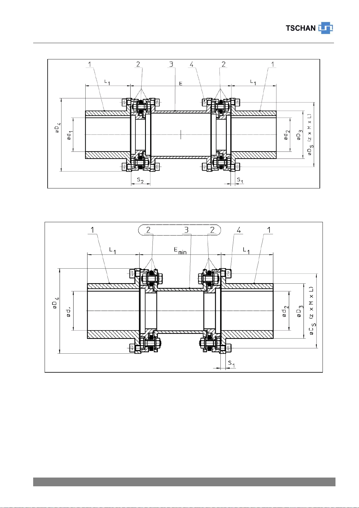
4 Construction .....................................................................................................................4
5 Technical Data .................................................................................................................5
6 Installation........................................................................................................................7
6.1 To be observed prior to installation:...........................................................................7
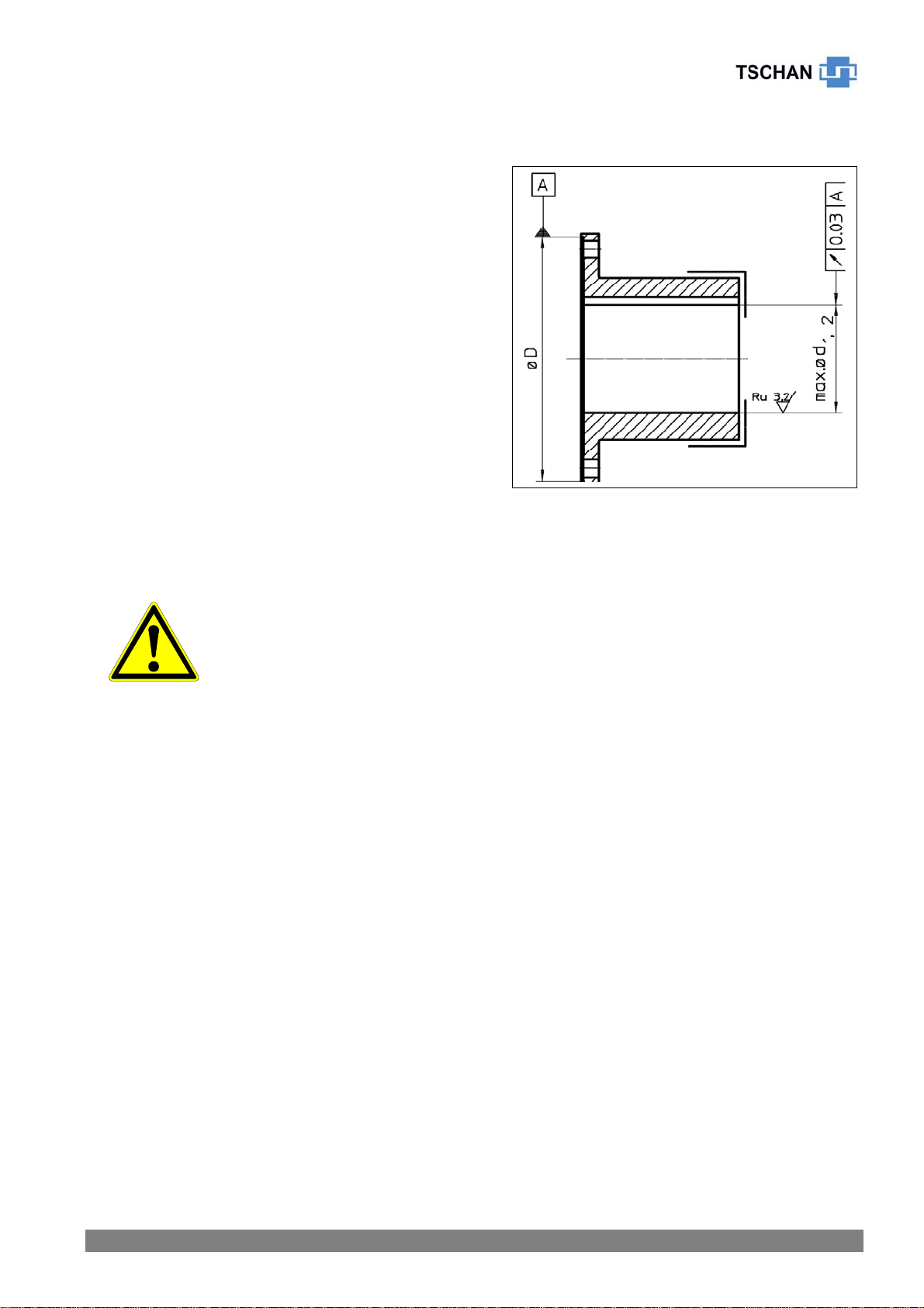
6.2 Finish bores...............................................................................................................8
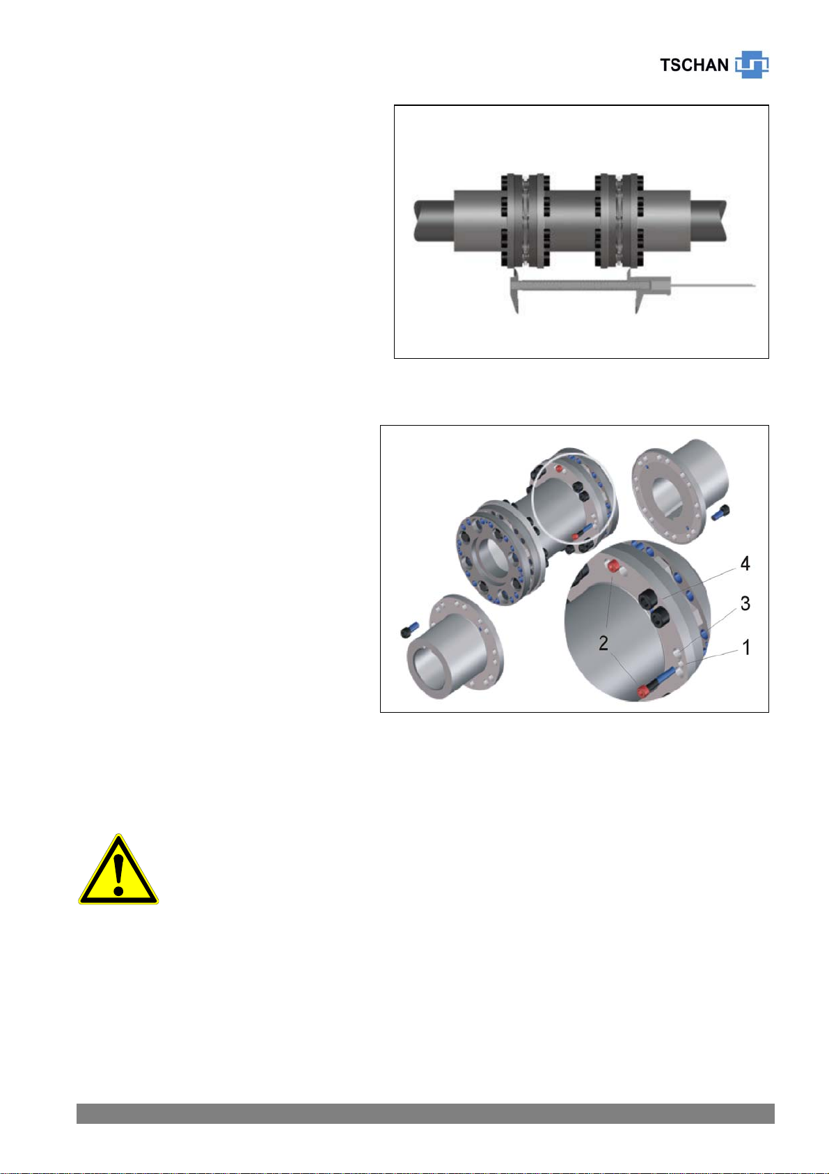
6.3 Coupling Installation ..................................................................................................9
7 Coupling Alignment ........................................................................................................ 11
7.1 Angular Misalignment ..............................................................................................12
7.2 Axial Misalignment...................................................................................................12
7.3 Radial Misalignment ................................................................................................13
8 Operation .......................................................................................................................14
9 Maintenance...................................................................................................................16
9.1 Disk Pack Inspection ...............................................................................................16
9.2 Disk Pack Replacement ..........................................................................................17
10 Disposal .........................................................................................................................18
11 Manufacturer’s Declaration ............................................................................................19
1 Safety Instructions
This installation and operation manual is an essential component of the coupling delivery.
Always keep this manual in a readily accessible place near the coupling.
Take care that all persons being charged with the installation, operation, maintenance and
repair of the coupling have read and understood this manual and that all instructions con-
tained therein are carefully observed in order to:
- avoid danger to life and limb of the user or third persons,
- ensure the operational safety of the coupling,
- preclude operation failures and environmental damages due to wrong handling and mis-
use.
- The relevant instructions and regulations regarding safety at work and environmental pro-
tection have to be observed while transporting, mounting and dismounting the coupling.
- Make sure that suitable handling and transportation means are at disposal.
- The coupling shall be operated, mounted, maintained and repaired by authorized, trained
and instructed personnel only.
- In the interest of further development, we reserve the right to carry out modifications serv-
ing the technical progress.
- We do not assume any liability or warranty for any damages resulting from the use of ac-
cessories and parts that are not originally manufactured by TSCHAN GmbH.

01/2004 POSIMIN®-PHP, -PHPmin - 3 -
2 Function
The TSCHAN®-Coupling POSIMIN®-PHP is a torsionally rigid steel disk coupling. It compen-
sates for angular, radial and axial shaft misalignments within defined ranges. The coupling
transmits torque without backlash through flexible steel disks loaded in tension.
The spacer can be radially mounted and dismounted without having to move the connected
machines. The distance dimension ‘E’ between the flange hubs can then be used, for exam-
ple, to service connected machines.
When the spacer is dismounted, a check of the rotational direction of the drive can easily be
performed.
The coupling is suitable for use in every direction of rotation and installation position. For ap-
plications involving other than horizontal position, it may be necessary to support the spacer.
Please consult TSCHAN GmbH, if this has not been considered when selecting the coupling.
2.1 Intended Application
• In order to ensure trouble-free and reliable operation, the coupling has to be sized accord-
ing to the design specifications, e.g. according to catalogue TSCHAN®POSIMIN®-PHP,
or by using the TSCHAN Design Programme, with a service factor appropriate for the ser-
vice conditions.
• Except for the production of a finish bore with keyway, no further modifications are al-
lowed to be carried out on the coupling!
• The coupling shall only be used and operated within the frame of the conditions as de-
fined in the performance or delivery contract.
• Any change in the operation conditions or service parameters requires the verification of
the coupling design.
3 Storage
On receipt of the goods, immediately check that all parts are on hand and are as ordered.
Eventual shipping damages and/or missing parts have to be reported in writing.
The coupling parts can be stored in a dry place under roof at normal ambient temperatures
for a time period of 6 months. Storage for a longer period requires the application of a long-
term preservation. (Please consult TSCHAN GmbH in this respect.)
The disk packs are made of stainless spring steel. They must not be exposed to any aggres-
sive products, extreme temperatures or humidity. Do not store the disk packs along with ac-
ids, alkaline solutions or other caustic chemicals. The place of storage should be dry and free
from dust. The air humidity should not exceed 65% and condensation is not permissible.

01/2004 POSIMIN®-PHP, -PHPmin - 4 -
4 Construction
Item Description
1 N-hub
2 Steel disk pack in sandwich construction
3 Spacer
4 Cheese head screw DIN 912
5 Clamping screw DIN 912 (not shown)
Important notes:
• The spacer, item 3, is delivered with fitted disk packs, item 2, as an easy-to-mount trans-
mission unit. In order to maintain the original balance state of this assembly, the flange
connections of the transmission unit must not be separated completely.
• Balanced assemblies are match marked. Bolt sets for balanced couplings are weight bal-
anced. These sets must not be mixed with bolt sets of other couplings!
• Upon final installation of the coupling, all cheese head screws, item 4, must be
tightened to the specified tightening torque!
Bild / Fig. 1 Construction PHP

01/2004 POSIMIN®-PHP, -PHPmin - 5 -
5 Technical Data
Bild / Fig. 2 POSIMIN PHP
Bild / Fig. 3 POSIMIN PHPmin

01/2004 POSIMIN®-PHP, -PHPmin - 6 -
Table 1 Technical Data:
Size TCnom
[Nm]
TCpeak
[Nm]
nmax
[min-1]
d1max
d2max
[mm]
E Stan-
dard
Emin
L1
[mm]
D3
[mm]
D4
[mm]
S1
[mm]
S2
[mm] M x L m
[kg]
157 2550 4600 11000 75 220
155 100 105 162 10 42,6 M10x25 21,0
15,9
178 4200 7500 10000 85 245
170 110 121 184 12 51,2 M12m30 31,2
24,3
202 6400 11400 8800 105 265
185 140 144 208 14 57,4 M14x35 46,9
37,1
235 10300 18500 7900 125 290
250 160 174 241 16 65 M16x40 72,3
59,2
277 18100 32600 6500 145 355
250 190 197 283 20 78 M20x50
119,8
93,0
332 31100 56000 5500 180 405
275 240 246 338 26 93,2 M24x60
213,8
170,7
386 44400 80000 4900 220 405
275 270 300 392 26 92,6 M24x60
295,8
243,0
420 62400 112400 4500 230 440
310 300 318 426 29 103 M27x65
395,0
323,7
508 110000 200000 3700 270 510
350 350 368 516 32 117 M33x80
689,6
533,0
Weight details m apply to max. bore d1, d2 and to the ‘E’-dimension stated in table 1.
The torques TCnom and TCpeak are valid for:
- Ambient temperatures of –30°C up to +150°C
- Operation within the range of the specified alignment values.
If the coupling has been dimensioned by means of the TSCHAN Design Programme,
deviations from these values may be permissible.
For determining the size of the coupling according to catalogue POSIMIN®-PHP, various fac-
tors have to be taken into account:
- the temperature factor Sυin case of higher temperatures,
- the start-up factor Sz depending on the frequency of starts,
- the shock factor SA, SLdepending on the service conditions.
For circumferential speeds above 30 m/s, based on the outer diameter of the coupling, we
recommend balancing the coupling parts.
Spacers, which are longer than the standard E-dimension, should be balanced in each case.

01/2004 POSIMIN®-PHP, -PHPmin - 7 -
6 Installation
6.1 To be observed prior to installation:
• Danger of injuries!
• Disconnect the drive before carrying out any work on the coupling!
• Secure the drive against unintentional re-start and rotating!
• Incorrectly tightened bolts can cause serious personal injuries and
property damages.
• Take care that suitable transportation means are at disposal and
that the transportation ways are free of obstacles.
• Take appropriate measures, such as sufficient ventilation of the operation site, good illu-
mination, proper electrical tools etc. to ensure safety, before mounting or putting the cou-
pling into operation and before carrying out any maintenance work.
• Before starting to install the coupling, make sure that the necessary tools are at disposal:
- to handle the parts
- to join the interfaces
- to align the coupling
- to tighten the screw connections.
• Make sure that the speeds, torques and ambient temperatures as stated in chapter 6
‘Technical Data’, or as defined by the TSCHAN Design Programme are not exceeded.
• The maximum permissible bore diameters must not be exceeded.
• Check whether the shaft-hub connections safely transmit the occurring operating torques.
• The standard tolerance of TSCHAN for finish bores is fit H7.
• Standard keyways comply with DIN 6885, sheet 1, fit P9.
• Check the dimensions and tolerances of shafts, hub bores, keys and keyways.
• Secure the hubs against axial movement on the shaft ends by using setscrews, shaft end
plates or by means of a sufficient interference fit.
• In compliance with accident prevention regulations, you are
obliged to protect all freely rotating parts by means of permanently
installed guards against unintentional contact and falling down ob-
jects.
• To avoid sparks, covers made from stainless steel should be used!
• As a minimum, the covers have to fulfil the requirements of protec-
tion type IP2X.
• The covers have to be designed to prevent dust from depositing on
the coupling.
• The cover must not contact the coupling or impair the proper func-
tion of the coupling.

01/2004 POSIMIN®-PHP, -PHPmin - 8 -
6.2 Finish bores
The following procedure has to be followed to
produce a finish bore in a coupling hub:
• Clean and remove all preservatives from the
coupling hubs.
• Mount the coupling hub in between the sur-
faces marked with éand carefully align the
hub according to the centering diameter ØD
and to the flange contact surface.
• The values for d1max, d2max as listed in table 1
are valid for keyed connections according to
DIN 6885/1 and must not be exceeded.
• Select the bore fit so that an interference fit
such as H7/m6 results when mating it with the
shaft tolerance.
• Secure the hub with a setscrew, shaft end
plate or suitable interference fit against axial
movement on the shaft end.
Consult TSCHAN GmbH in case of other shaft-hub connections.
• The stated maximum bore diameters are valid for keyed connec-
tions according to DIN 6885/1 and must not be exceeded.
• If these values are exceeded, the coupling can break.
• Flying off coupling fragments are a danger to life!

01/2004 POSIMIN®-PHP, -PHPmin - 9 -
Bild / Fig. 4
6.3 Coupling Installation
Prior to installation, carefully clean the bores of the coupling hubs and the shaft ends. The
surfaces must be clean, dry and free of grease.
For larger couplings use suitable mounting tools and hoisting devices such as cranes or pul-
ley blocks.
Mount the coupling hubs in the proper position on the shaft ends (Fig. 4).
Note:
To facilitate mounting, the hub can be uniformly heated to 80°C to 120°C.
Warning!
Always wear heat-resistant gloves to protect yourself against injuries
due to hot coupling components!
Mount the hubs in such a manner that
the shaft end is even with the inner
bore opening (Fig. 4). Projecting shaft
ends prevent radial mounting and re-
moval of the spacer. Observe deviant
agreements, which may exist. When
tightening possibly installed setscrews,
secure them with an adhesive, such as
e.g. Loctite 222, to prevent the screws
from working loose and dropping out.

01/2004 POSIMIN®-PHP, -PHPmin - 10 -
Bild / Fig. 6
• Before mounting the pre-assembled
transmission unit, perform an initial
alignment over the hub flanges by us-
ing an appropriate tool, e.g. a
straightedge. The shaft ends should
be flush with each other.
• The hub flanges must be parallel to
each other. Also refer to chapter 7
‘Coupling Alignment’.
• Check correct distance dimension
‚E’. See Fig. 5 and chapter 7 ‘Cou-
pling alignment’.
• The bearing surfaces of the fastening
elements on the flanges and disk
packs must be clean, dry and free of
grease.
• Remove the cheese head screws,
item 3, that are located on the right
and left side of the clamping screw
bores, item 1, and compress the
disk packs at the spacer by using
the red clamping screws.
• Do not loosen the flange bolting,
item 4, between the disk packs and
the spacer in order to maintain the
original balance state of the
transmission unit!
• Mount the transmission unit with
fitted disk packs in between the
hubs (Fig. 6).
• Remove the red clamping screws,
item 2, and let the flanges of the
disk packs slide into the centering
seats of the hubs. Take care that the
parts do not become canted in the centering seats.
• Observe the position markings of balanced components/ assemblies!
• Insert all the cheese head screws, items 3 + 4, to connect the flanges.
Use the cheese head screws as they were delivered, i.e. slightly oiled. Do
not clean or additionally lubricate the fastening elements!
• Slightly tighten the screws by hand.
• Tighten the screws progressively one after the other in small increments
until the tightening torque MAstated in table 2 is reached. Also check the screw connec-
tions on the pre-assembled transmission unit!
• Align the coupling according to the instructions given in chapter 7 ‘Coupling Alignment’.
Bild / Fig. 5

01/2004 POSIMIN®-PHP, -PHPmin - 11 -
Table 2 Tightening torques MAof cheese head screws in ‘slightly oiled’ de-livery
state:
Size 157 178 202 235 277 332 386 420 508
Thread M10 M12 M14 M16 M20 M24 M24 M27 M33
MA[Nm] 66 115 180 280 550 950 950 1400 2500
7 Coupling Alignment
§ Danger of injuries!
§ Disconnect the drive before carrying out any work on the
coupling.
§ Secure the drive against unintentional re-start and rotating!
§ Note:
§ Accurate alignment of the coupling prolongs the lifetime of the disk
packs and reduces the risks when operating the coupling.
§ It is of utmost importance to observe the recommended alignment
values. Exceeding the permissible misalignment values results in
coupling damages and failures!
- When aligning the cold equipment take into account the expected thermal growth of the
components, so that the permissible misalignment values for the coupling are not ex-
ceeded in operation.
- Be aware that the coupling under misalignment imposes restoring forces on the adjacent
shafts and bearings. Take into account that the larger the misalignment, the greater the
restoring forces will be.
- The total angular misalignment, combined of radial and angular displacement, for
each disk pack must never exceed the following values during operation:
Size 157 178 202 235 277 332 386 420 508
∆kwmax. 0,33° 0,33° 0,33° 0,33° 0,33° 0,33° 0,33° 0,33° 0,25°

01/2004 POSIMIN®-PHP, -PHPmin - 12 -
Bild / Fig. 7
7.1 Angular Misalignment
• Measure one complete revolution on
the face of the outer diameter. To
this purpose, turn the dial gauge by
360°. Determine the largest devia-
tion Kw1 and the smallest deviation
Kw2 (Fig. 7). Calculate the angular
misalignment:
∆Kw = Kw1 – Kw2.
• When aligning, observe the max.
permissible angular misalignment
∆Kwmax acc. to table 3.
Table 3 Recommended Alignment Values - Angular Misalignment:
Size 157 178 202 235 277 332 386 420 508
∆Kwmax [mm] 0,2 0,2 0,25 0,3 0,3 0,35 0,45 0,5 0,45
7.2 Axial Misalignment
• Before installing the transmission
unit measure the actual length di-
mension „E“ of the transmission unit
over the outer flanges of the disk
packs (Fig. 8).
• Set the distance between the con-
tact surfaces in the flange hubs to a
dimension between E and (E + ∆e)
acc. to table 4. Do not exceed the
tolerances stated in table 4.
Table 4 Recommended tolerance values ∆e for dimension ‘E’:
Size 157 178 202 235 277 332 386 420 508
∆e [mm] 0,5 0,5 0,5 0,7 0,8 0,8 0,6 0,7 0,7
ATTENTION!
Make sure not to fall below the dimension ‘E’, as otherwise it is not possible to radially
mount the transmission unit!
Bild / Fig. 8

01/2004 POSIMIN®-PHP, -PHPmin - 13 -
Bild / Fig. 9
If larger axial displacements are to be anticipated during operation, e.g. due to thermal
growth, the coupling can be mounted with axial pre-stretch to account for the expected
growth. This item has to be discussed with TSCHAN GMBH, if it has not been considered
when designing the coupling. In service, the coupling shall run in unconstrained manner with
dimension ‘E’.
7.3 Radial Misalignment
• Measure one complete revolution. To
this end, turn the dial gauge by 360°.
Determine the largest deviation Kr1
and the smallest deviation Kr2
(Fig. 9).
Calculate the radial misalignment ∆Kr
= 0,5 x (Kr1 – Kr2). Observe the pre-
ceding sign of the measured values.
• When aligning, observe the maxi-
mum permissible radial misalignment
in dependence of the centre distance
of the disk packs ‘MLP’.
∆Krmax = MLP/1000 [mm]
• For verification purposes, this meas-
urement should also be performed on
the second coupling half.
• The alignment must be corrected in case of any deviations.

01/2004 POSIMIN®-PHP, -PHPmin - 14 -
8 Operation
When operating the coupling, its specific technical data have to be carefully observed (see
chapter 6 ‘Technical Data’). These values must never be exceeded without the prior written
approval by TSCHAN GmbH.
In order to ensure trouble-free and reliable performance of the coupling, the coupling has to
be designed according to the selection specifications, e.g. according to catalogue POSIMIN®-
PHP or by using the TSCHAN Design Programme, with a service factor appropriate to the
service conditions.
Any change in the service conditions or service parameters always necessitates the verifica-
tion of the coupling design!
§ Danger of injuries!
§ Disconnect the drive before carrying out any work on the coupling!
§ Secure the drive against unintentional re-start and rotating!
§ Improperly tightened screws may cause parts to fly off what leads
to most serious personal injuries and property damages!
§ Before putting the coupling into operation, check the alignment and
all screwed connections for correct tightening torque or firm fit!
§ Before starting up the equipment, install all protective guards in
order to avoid unintentional contact with freely moving or rotating
parts.
§ To avoid sparks, covers made of stainless steel should be used!
§ The covers have to comply with protection type IP2X as a mini-
mum.
§ The cover shall be designed to prevent dust from depositing on
the coupling parts.
§ The cover must not touch the coupling and must not impair the
proper function of the coupling.
While operating the coupling, pay attention to:
§ Changes in operating noises
§ Vibrations
§ Lost parts
Attention!
• Disconnect the drive immediately, if any irregularities are observed while operating
the coupling!
• Identify the cause for the problem using table 5 below “Operation Faults and Possible
Causes“ and correct the fault.
The listed problems are some examples to assist you in troubleshooting.
• All the machinery components and operation modes have to be considered for the
determination and correction of faults!

01/2004 POSIMIN®-PHP, -PHPmin - 15 -
Table 5 Operation Faults and Possible Causes:
Trouble Cause Risk Warning Correction
Alignment fault Increased restoring
forces on shafts
and bearings of the
connected ma-
chines.
- Disconnect drive
- Remove cause for alignment fault
- Re-align coupling
- Check disk packs for damages such
as cracks, dents or similar damages,
and replace them, if necessary
Damaged disk
packs
Disk breakage,
spacer can fly out
- Disconnect drive
- Check coupling components for
damages and replace parts, if nec-
essary
- Check alignment
- Verify coupling design
- Replace disk packs
- Verify balance state of plant compo-
nents and correct it, if necessary
Unbalance Vibrations, disk
breakage
- Disconnect drive
- Check disk packs for damages, such
as cracks, dents or similar damages,
and replace them, if necessary
- Verify balance state of plant compo-
nents and correct it, if necessary
Running
noises/
vibrations
Loose screw
connections
Spacer can fly out
- Disconnect drive
- Check coupling parts for damages,
replace parts, if necessary
- Verify alignment of coupling
- Tighten nuts with the specified
tightening torque
Alignment fault
s
Increased restoring
forces on shafts
and bearings of the
connected ma-
chines
- Disconnect drive
- Remove cause for alignment fault
- Re-align coupling
- Replace disk packs
- Verify balance state of plant compo-
nents and correct it, if necessary
Overloading
due to very hig
h
torque
Disk breakage,
spacer can fly out
- Disconnect drive
- Verify coupling design in cooperation
with TSCHAN GmbH
- Replace coupling
- Install larger coupling, if necessary
Disk pack
damages
Contact with
aggressive
products
Disk breakage,
spacer can fly out
- Disconnect drive
- Check coupling parts for damages
and replace parts, if necessary
- Replace disk packs
- Verify balance state of plant compo-
nents and correct it, if necessary
- Verify alignment of coupling
- Prevent contact with aggressive
products

01/2004 POSIMIN®-PHP, -PHPmin - 16 -
Trouble Cause Risk Warning Correction
Torsional vibra-
tions in the
drive line
Disk breakage,
spacer can fly out
- Disconnect drive
- Analyse and eliminate cause for tor-
sional vibrations
- Check coupling parts for damages
and replace parts, if necessary
- Verify coupling alignment
9 Maintenance
The torsionally rigid disk coupling POSIMIN®-PHP does not need maintenance during opera-
tion.
On the occasion of routine inspections or maintenance of the equipment, check:
• alignment of coupling
• state of disk packs
• firm fit of all fastening elements
• lost parts
• remove dust deposits from coupling parts and disk packs.
9.1 Disk Pack Inspection
§ Danger of injuries!
§ Disconnect the drive before carrying out any work on the
coupling!
§ Secure the drive against unintentional re-start and rotating!
• Visually inspect the disk packs after 2000 hours, however after 3 months at latest, after
the first start-up. If this first inspection does not reveal any damages such as cracks or
dents on the disks, further inspections may be conducted at regular intervals of 4000
hours, however, at least once a year, provided that the operation modes and service con-
ditions of the equipment are not altered.
• If damages of the disk packs are already detected on the occasion of this first inspection,
verify whether the cause for the problem is listed in table 5 “Operation faults”. It is essen-
tial to adapt the inspection intervals to the prevailing operation conditions.
• Under special operation conditions it may be necessary to perform inspections and main-
tenance operations at shorter intervals than stated.

01/2004 POSIMIN®-PHP, -PHPmin - 17 -
Bild / Fig. 10
9.2 Disk Pack Replacement
§ Danger of injuries!
§ Disconnect the drive before carrying out any work on the
coupling!
§ Secure the drive against unintentional re-start and rotating!
• Secure the spacer against falling
down.
• Remove the cheese head screws
from the flange connections in the
hubs.
• Compress the disk packs with the
red clamping screws. See Chapter 6
‘Installation’, Fig. 6. This work can
be facilitated by using the jacking
screws in the hub flanges.
• Radially lift out the spacer along with
the disk packs of the hub flanges.
For larger couplings use appropriate
tools and lifting devices such as
cranes or blocks and tackles (Fig. 10).
• Type PHP:
Remove the sandwich disk packs.
• Check the coupling parts for damages.
• Insert the new sandwich disk packs into the centerings at the spacer and fasten them by
using the cheese head screws, which are not situated in the bores for the clamping
screws.
• For balanced couplings it is suggested to newly balance the transmission unit together
with the fitted disk packs.
• Type PHPmin:
The spacer has to be replaced together with the bushed disk packs. The disk pack at the
spacer can only be replaced at the supplier’s factory.
• Compress the new sandwich disk packs with the red clamping screws.
• For further way of proceeding, see chapter 6 ‘Coupling Installation’.
• Verify the alignment of the coupling according to chapter 7 ‘Coupling Alignment’.
Attention!
§ Before putting the equipment into service, all safety guards must
be installed to prevent unintentional contact with freely rotating
parts.
§ To avoid sparks, covers made from stainless steel should be used.
§ The covers have to fulfil the requirements of protection type IP2X
as a minimum.
§ The covers have to be designed to prevent dust from depositing on
the coupling parts.
§ The cover must not touch the coupling and impair the proper op-
eration of the coupling.

01/2004 POSIMIN®-PHP, -PHPmin - 18 -
We do not assume any responsibility or warranty for any damages resulting from the use of
accessories or spare parts, which have not originally been supplied by TSCHAN GmbH.
10 Disposal
Disposal of the parts must be arranged in accordance with the regulations and laws of the
country where the equipment is installed.

TSCHAN GmbH Zweibrücker Straße 104 D-66538 Neunkirchen-Saar
Telefon: +49(0) 6821 866 0 Telefax: +49(0) 6821 883 53 www.tschan.de
11 Manufacturer’s Declaration
according to the spirit of the EC Machinery Directive 98/37/EG Annex II B
We herewith declare that the
torsionally rigid shaft couplings of type
POSIMIN®-PHP, -PHPmin
described in this operation manual are intended for installation in a machine, and that its start up
is only allowed after it has been determined that the machine into which this component will be
installed, complies with the requirements of the EC-Directive.
Neunkirchen, Jan. 30, 2004
i. V. Norbert Telaar
Sales and Design Manager i. V. Volker Carl
Design Manager
This manual suits for next models
1
Table of contents
Other TSCHAN Industrial Equipment manuals
Popular Industrial Equipment manuals by other brands

Bosch
Bosch Rexroth 3 842 560 099 operating manual

RSTEEL
RSTEEL RVL-N Single Technical manual

Denios
Denios HazMat DPO-Z Operation manual

Kelvin
Kelvin RH015 Installation, operation and maintenance manual

Cleveland
Cleveland SPLASH PROOF SET-10 Installation, operation, maintenance, parts

ABB
ABB XAC25880 Operation manual

Jäger
Jäger Z120-H824.12 S11W2V manual

Mitsubishi Electric
Mitsubishi Electric ZKB AN Series instruction manual

OETIKER
OETIKER FAST 3000 operating instructions

Riftek
Riftek RF1010SS Series user manual

Grundfos
Grundfos PowerAdapt Installation and operating instructions

Siemens
Siemens 3RK1903-1BA00 PM-D F1 Original operating instructions