TSI Incorporated 8372 Operation manual

Model 8372/73
ACCUBALANCE®Plus
Air Capture Hood
Operation and Service Manual
1980336, Revision C
October 2002
Ventilation Testin
g
/Balancin
g


Model 8372/73
ACCUBALANCE®Plus
Air Capture Hood
Operation and Service Manual
1980336, Revision C
October 2002
U.S.
Sales and Customer Service:
1-(800) 874-2811 USA/
001-(651) 490-2811
Fax:
001-(651) 490-3824
MAIL TO:
TSI Incorporated
500 Cardigan Road
Shoreview, MN 55126-3996
USA
E-mail address:
Website:
http://www.tsi.com


Copyright
TSI Incorporated / October 2002 / All rights reserved.
Address
TSI Incorporated / 500 Cardigan Road / Shoreview, MN 55126 / USA
Fax No.
(651) 490-3824
LIMITATION OF WARRANTY AND LIABILITY (effective July 2000)
Seller warrants the goods sold hereunder, under normal use and service as described in the
operator's manual, shall be free from defects in workmanship and material for twenty-four (24)
months, or the length of time specified in the operator's manual, from the date of shipment to the
customer. This warranty period is inclusive of any statutory warranty. This limited warranty is
subject to the following exclusions:
a. Hot-wire or hot-film sensors used with research anemometers, and certain other
components when indicated in specifications, are warranted for 90 days from the date of
shipment.
b. Parts repaired or replaced as a result of repair services are warranted to be free from
defects in workmanship and material, under normal use, for 90 days from the date of
shipment.
c. Seller does not provide any warranty on finished goods manufactured by others or on any
fuses, batteries or other consumable materials. Only the original manufacturer's warranty
applies.
d. Unless specifically authorized in a separate writing by Seller, Seller makes no warranty
with respect to, and shall have no liability in connection with, goods which are
incorporated into other products or equipment, or which are modified by any person other
than Seller.
The foregoing is IN LIEU OF all other warranties and is subject to the LIMITATIONS stated
herein. NO OTHER EXPRESS OR IMPLIED WARRANTY OF FITNESS FOR
PARTICULAR PURPOSE OR MERCHANTABILITY IS MADE.
TO THE EXTENT PERMITTED BY LAW, THE EXCLUSIVE REMEDY OF THE USER OR
BUYER, AND THE LIMIT OF SELLER'S LIABILITY FOR ANY AND ALL LOSSES,
INJURIES, OR DAMAGES CONCERNING THE GOODS (INCLUDING CLAIMS BASED
ON CONTRACT, NEGLIGENCE, TORT, STRICT LIABILITY OR OTHERWISE) SHALL
BE THE RETURN OF GOODS TO SELLER AND THE REFUND OF THE PURCHASE
PRICE, OR, AT THE OPTION OF SELLER, THE REPAIR OR REPLACEMENT OF THE
GOODS. IN NO EVENT SHALL SELLER BE LIABLE FOR ANY SPECIAL,
CONSEQUENTIAL OR INCIDENTAL DAMAGES. SELLER SHALL NOT BE
RESPONSIBLE FOR INSTALLATION, DISMANTLING OR REINSTALLATION COSTS
OR CHARGES. No Action, regardless of form, may be brought against Seller more than 12
months after a cause of action has accrued. The goods returned under warranty to Seller's
factory shall be at Buyer's risk of loss, and will be returned, if at all, at Seller's risk of loss.
Buyer and all users are deemed to have accepted this LIMITATION OF WARRANTY AND
LIABILITY, which contains the complete and exclusive limited warranty of Seller. This
LIMITATION OF WARRANTY AND LIABILITY may not be amended, modified or its terms
waived, except by writing signed by an Officer of Seller.
Service Policy
Knowing that inoperative or defective instruments are as detrimental to TSI as they are to our
customers, our service policy is designed to give prompt attention to any problems. If any
malfunction is discovered, please contact your nearest sales office or representative, or call TSI's
Customer Service department at (651) 490-2811 or (800) 874-2811
.


CONTENTS
ABOUT THIS MANUAL .............................................................III
INTRODUCTION ........................................................................IV
Chapters
1. SET UP..................................................................................1
Unpacking..............................................................................1
Parts Identification.................................................................3
Display...................................................................................3
Display Units..........................................................................5
Keypad ..................................................................................5
Changing the Real-Time Clock .............................................6
Compliance Statement for Y2K.............................................7
Changing the Baud Rate.......................................................7
Preparing the Instrument for Use..........................................7
Installing the Batteries.....................................................7
Hood Assembly...............................................................8
Basic Operation.....................................................................9
Start-Up...........................................................................9
Selecting Flow Direction .................................................9
Taking a Flow Measurement ........................................10
Turning the ACCUBALANCE Plus Off ..............................10
Automatic Shut-off ........................................................11
2. OPERATIONS IN MORE DETAIL......................................13
Keypad Functions................................................................13
Field Calibration - Model 8372 Only....................................24
Additional Keypad Functions for the Model 8373 ...............24
Field Calibration - Model 8373 Only....................................25
Changing Hoods..................................................................26
Changing DIP Switch Settings ............................................30
Switch Number....................................................................31
Connecting the Optional Printer..........................................31
Connecting to a Computer ..................................................33
Downloading Data to a Computer.......................................33
Data Acquisition (Polling)....................................................33
3. MAINTENANCE..................................................................35
Fabric Hood.........................................................................35
Meter ...................................................................................36
Manifold...............................................................................36
Cases ..................................................................................36
Calibration ...........................................................................36

ii
4. TROUBLESHOOTING........................................................37
Appendixes
A. BACK PRESSURE .............................................................41
B. SPECIFICATIONS...............................................................43

About this manual
This manual explains how to set up, operate and maintain the
Model 8372/8373 ACCUBALANCE®Plus Air Capture Hood. Read it
thoroughly before using the instrument.
Formatting and Typography
Note that step-by-step instructions are numbered in boldface type: 1,2,3,
etc., set flush-left against the margin.
References to the front panel keys on the ACCUBALANCE Plus, along with
the instrument's displayed readout, are represented in this manual by the
typeface called Arial Narrow. In addition to the different typeface, displayed
messages appear in quotes.
When reference is made to other sections of the manual, the section title is
italicized.
Example: The “SAMPLE” message will appear along with a flow value after
you have activated the SAMPLE key (from Display in Chapter 1).
HELP!
If you need technical assistance with this instrument, have questions about
the manual, or your air capture hood needs repair or recalibration please call
TSI's Environmental Measurements and Control Division at (651) 490-2811
or (800) 874-2811. Product application notes are designed to provide more
information on the product to the user. Application notes, as well as other
related material, can be obtained by calling TSI or by visiting the TSI web
site at http://www.tsi.com.

iv
Introduction
The TSI Models 8372/8373 ACCUBALANCE®Plus are instruments designed
to measure the air flow from diffusers and grilles or the air flow entering
exhaust outlets. The ACCUBALANCE Plus is lightweight and easy to use.
The instrument can display the measured air flow in four different units:
standard cubic feet per minute (SCFM), standard liters per second (Std l/s),
standard cubic meters per hour (Std m3/hr), and standard cubic meters per
minute (Std m3/min). All readings may also be displayed in actual flow
conditions.
The ACCUBALANCE Plus consists of a fabric hood, a molded plastic base
which contains an electronic meter, and a flow sensing manifold located
within the base. Air flowing through the hood is measured by a hot-film
sensor located in the central hub of the flow sensing manifold. The twenty-
four pairs of flow sensing ports in the manifold are strategically located so
that the ACCUBALANCE Plus provides the highest degree of measurement
accuracy, even in non-uniform flow conditions.
The ACCUBALANCE Plus is temperature-compensated to display a standard
flow rate: SCFM, Std l/s, Std m3/hr, and Std m3/min. Standard flow rate is
defined as the volumetric flow rate at standard conditions of 70°F (21.1°C)
and 14.7 pounds per square inch (760 mmHg) barometric pressure.
Standard flow rate is the measurement used most often in ventilation
applications.
1
Chapter 1
Set Up
This chapter guides you through unpacking, setting up, and getting started
using your ACCUBALANCE Plus. See Chapter 2 for a detailed description of
all operating features.
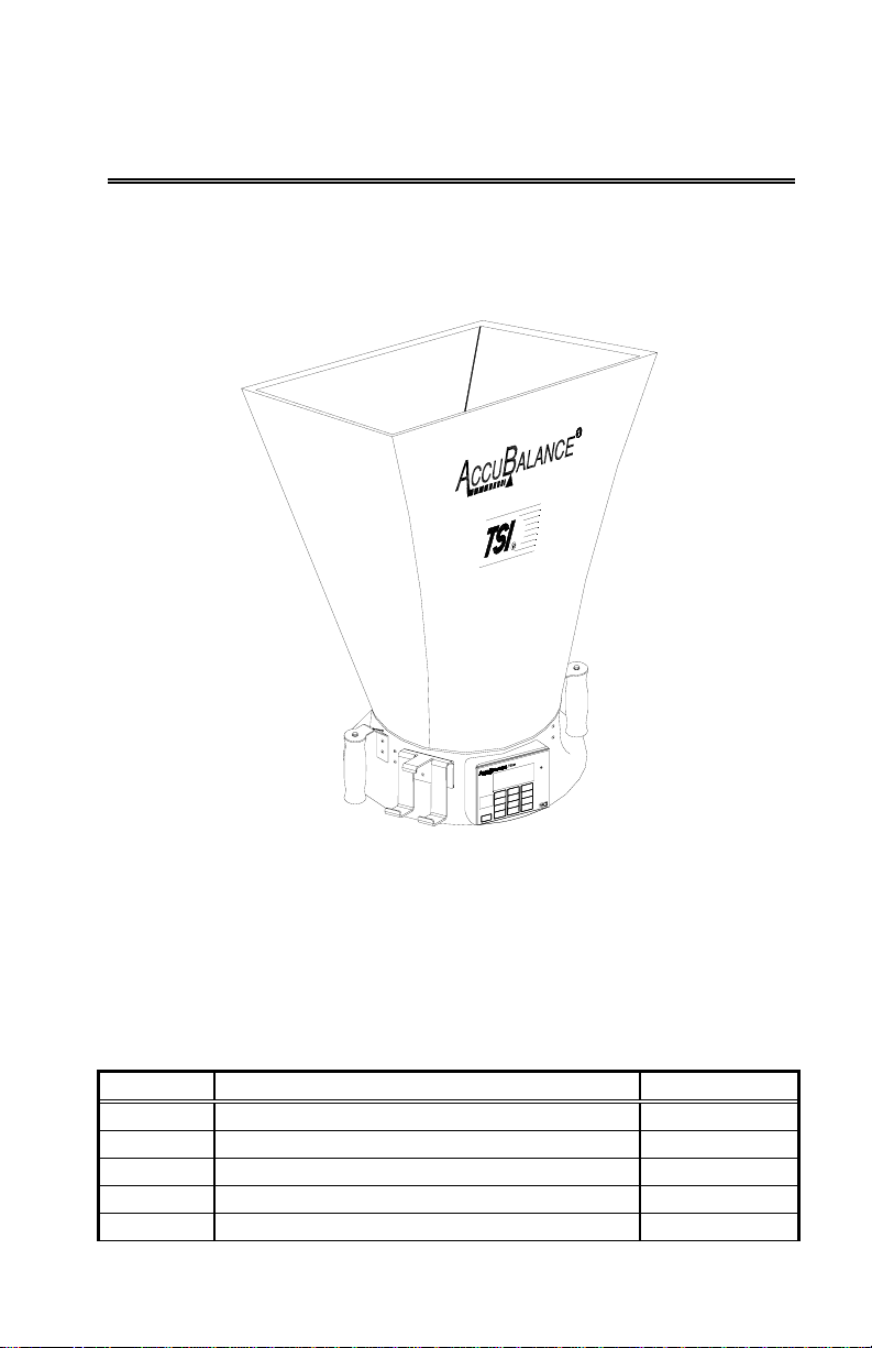
Figure 1: The ACCUBALANCE Plus
Unpacking
Carefully unpack the instrument and accessories from the carrying case.
Check the individual parts against the list of components in Tables 1 through
3. If any are missing or damaged, notify TSI immediately.
Table 1 List of components
Qty Item Part No.
1 Model 8372/8373 base N/A
1 2 ft x 2 ft (610 mm x 610 mm) hood fabric 1307060
6 Frame support poles 1081390
4 2 ft (610 mm) frame tubing* 1081262
6 Right angle tubing connectors* 1081584
2 Chapter 1
Qty Item Part No.
1 Battery holder 1081279
4 C-size batteries 1208018
1 Battery compartment cover 1081458
1 Carrying case 1319067
1 Operation and Service Manual 1980336
1 Data download RS232 cable 1082798
3 3½” floppies containing the “Logdat” data
download software 800832
*Four of the 2 ft frame tubings and four of the right angle connectors are
shipped assembled inside the top of the hood fabric.
Table 2 List of components: -3 Hood Kit (adds 2 hoods to the
base kit)
Qty Item Part No.
1 2 ft x 4 ft (610 mm x 1220 mm) hood fabric 1801065
1 1 ft x 4 ft (305 mm x 1220 mm) hood fabric 1801066
6 2 ft (610 mm) frame tubing 1081262
4 1 ft (305 mm) frame tubing 1081260
6 Right angle tubing connectors 1081584
6 Straight tubing connectors 1302833
Table 3 List of components: -5 Hood Kit (adds 4 hoods to the
base kit)
Qty Item Part No.
1 2 ft x 4 ft (610 mm x 1220 mm) hood fabric 1801065
1 1 ft x 4 ft (305 mm x 1220 mm) hood fabric 1801066
1 1 ft x 5 ft (305 mm x 1525 mm) hood fabric 1801067
1 3 ft x 3 ft (915 mm x 915 mm) hood fabric 1801068
6 2 ft (610 mm) frame tubing 1081262
4 1 ft (305 mm) frame tubing 1081260
6 Right angle tubing connectors 1081584
6 Straight tubing connectors 1302833
2 1x tube connectors 1081580
Included with this product is a registration card. Please complete and mail it
promptly; it allows TSI to inform you of product updates. You may also
register on line by visiting the TSI web site.
Set Up 3
Parts Identification
Before proceeding with assembly and use of the ACCUBALANCE Plus, please
familiarize yourself with the various parts of the instrument. Refer to
Tables 1 through 3 for part descriptions and Figure 2 for general location of
major items.
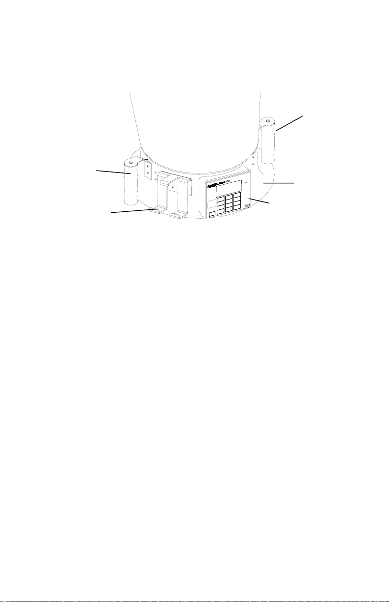
Figure 2: ACCUBALANCE components
1Fabric hood - Basic hood assembly is covered later in this chapter,
other hoods are discussed in Chapter 2.
2Right handle with SAMPLE key - used for capturing information on the
display.
3Meter base
4Electronic meter and display - Detailed keypad functions are covered
in Chapter 2.
5Printer bracket - Allows the Model 8925 to be attached to the
ACCUBALANCE base for ease of use and recording of data.
6Left handle with PRINT button - Used to print that which is on the
display value to the portable printer.
Display
Each time the ACCUBALANCE is turned on, all segments of the display will
be shown momentarily. Below is a list of items that will appear on the
display and their use.
2
3
5
6
4
1
4 Chapter 1
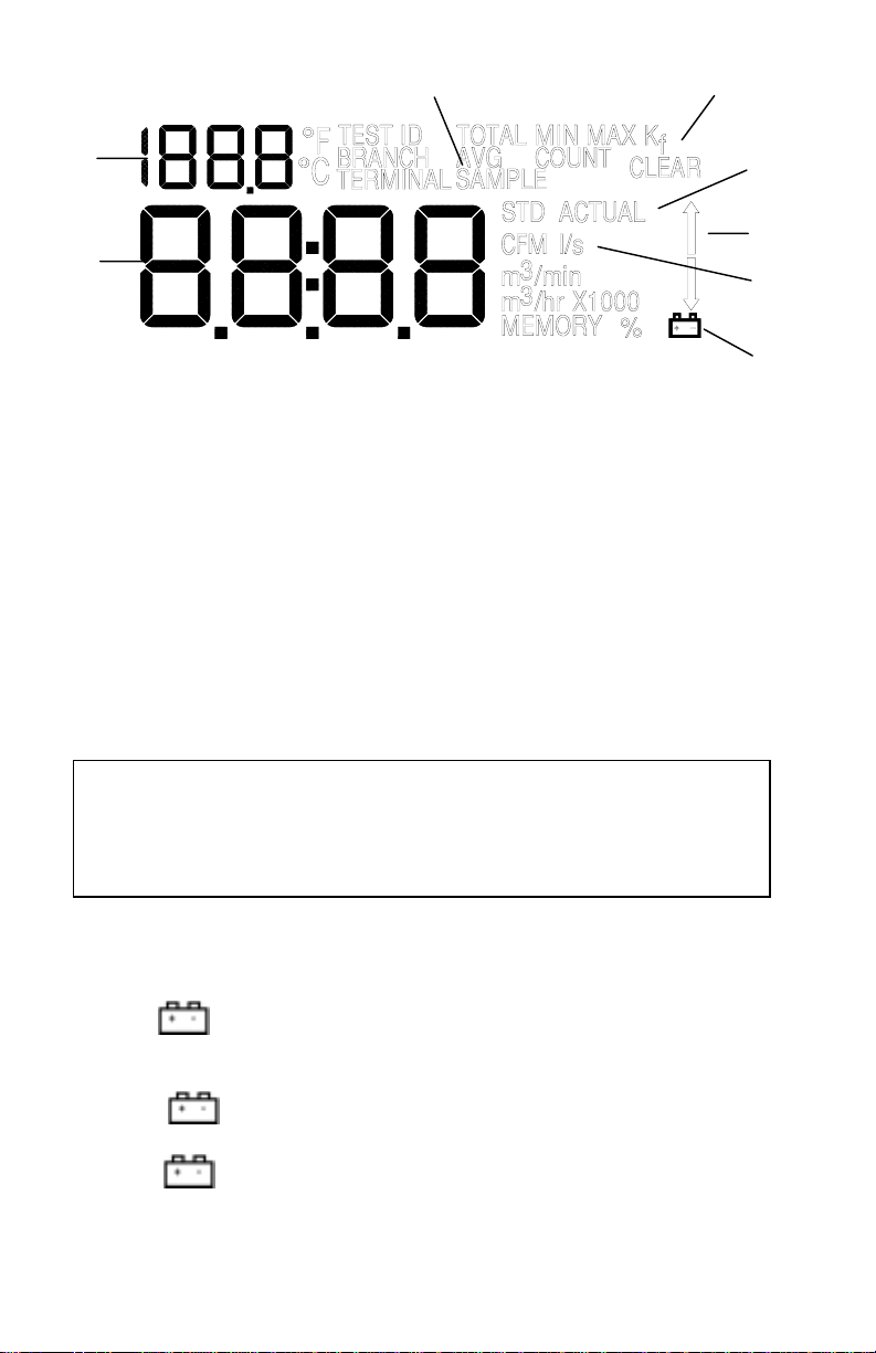
Figure 3: Display of the Model 8372/8373
1Flow units: CFM (cubic feet per minute), l/s (liters per second), m3/hr
(cubic meters per hour), and m3/min (cubic meters per minute). The
ACCUBALANCE indicates flow already corrected to "standard"
conditions. Actual flow conditions can be shown by pressing the
ACTUAL/STANDARD key (see Chapter 2 for more detail operation).
2Flow value: Large digits. See specifications for range and resolution.
3Message area: Small digits. Simultaneous temperature measurement.
4Flow direction arrows: Indicates if supply or return air flow
calibration is being utilized by the ACCUBALANCE.
Notice: For Model 8372 - Be sure this arrow points in the direction of flow
through the ACCUBALANCE Plus,otherwise the measurements made
will be inaccurate. To change the direction of the arrow, press the
SUPPLY/RETURN key. (The Model 8373 senses direction
automatically)
5”SAMPLE” will appear every time you press the SAMPLE key or the
button on the top of the right handle.
6“% “will appear along with a value on the display during power-
up to indicate the percent of battery life remaining.
7The symbol will flash when the batteries have only about 10%
life remaining. When the battery is too low for accurate measurements
“LO “is displayed momentarily before the instrument is
automatically turned off.
3
2
5 9
8
4
6,7
1

Set Up 5
8“STD” or “ACTUAL” will be displayed at all times. “STD” refers to
readings that are based on standard conditions of 29.92 in. Hg (760
mm Hg) and 70 °F (21.1 °C). “ACTUAL” refers to readings that are
converted to local conditions based on temperature and barometric
pressure.
9“Kf”: K factor symbol to indicate that the readings have an adjustment
factored in.
10 “TOTAL”, “MIN”, “MAX”, “AVG”, “COUNT” will be displayed when viewing
STATISTICS.
11 “TEST ID”, “BRANCH”, “TERMINAL” will be displayed when viewing data
for a SAMPLE or when reviewing data.
Display Units
The ACCUBALANCE Plus is shipped with cubic feet per minute (CFM) as the
default flow unit, °F for temperature, and in. Hg (inches of mercury) for
barometric pressure (unless the metric version was ordered). If you wish to
change the units to l/s (liters per second), m3/hr (cubic meters per hour),
m3/min (cubic meters per minute), °C for temperature, and mm Hg
(millimeters of mercury) for barometric pressure, see Changing DIP Switch
Settings in Chapter 2. Please note that no units will be shown on the display
for barometric pressure.
Keypad
Below is a drawing of the key pads, Figure 4, for the Model 8372, Figure 5,
for the Model 8373. The keys are referenced in the Basic Operation section
of this chapter and in Chapter 2 - Operations in More Detail.
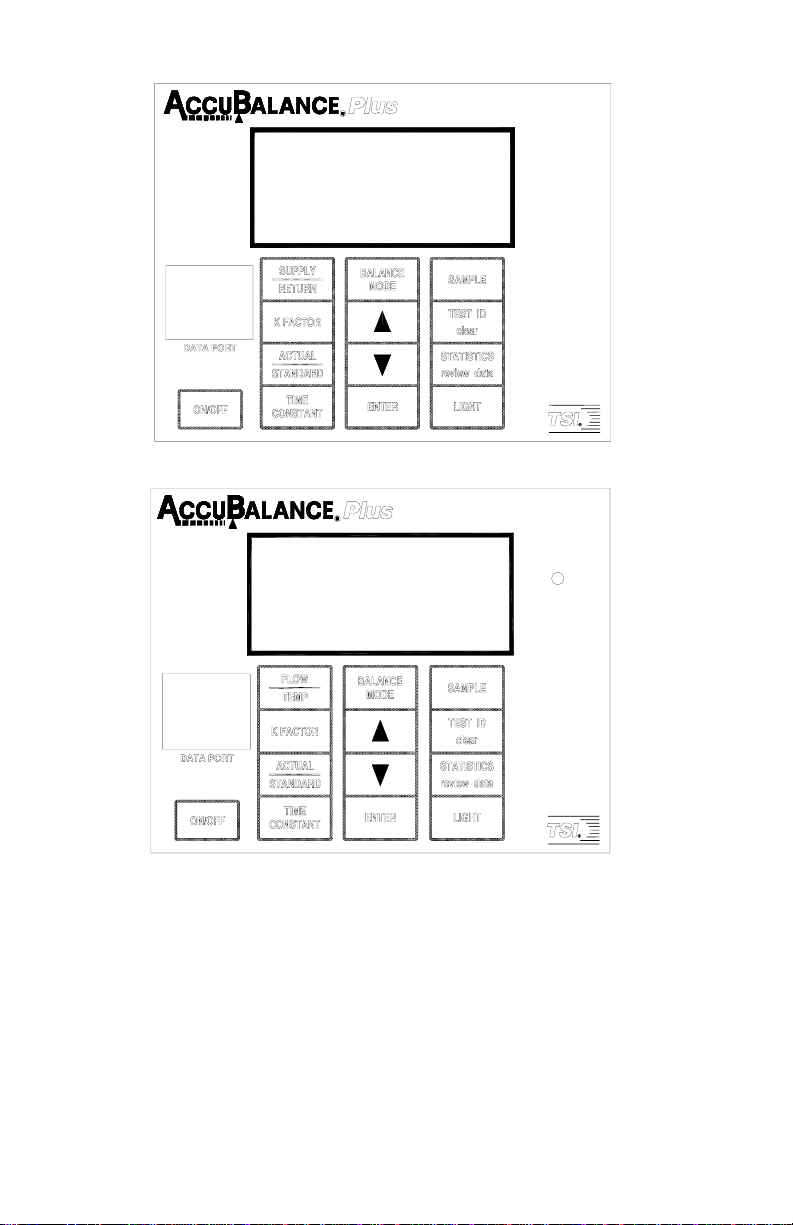
6 Chapter 1
Figure 4: Keypad for the Model 8372
Figure 5: Keypad for the Model 8373
Changing the Real-Time Clock
The ACCUBALANCE Plus has an internal real-time clock that keeps track of
the time of day (the format is HH.MM where HH is the hour in 24-hour
format and MM is minutes) and the date. It is very important to set the time
and date correctly, otherwise date and time stamping of recorded data will
not be correct. This information has been set to Central Time (GMT - 6
hours) (Standard or Daylight Savings) at the factory before shipping. The
ACCUBALANCE Plus does not self-adjust for Daylight Savings Time.

Set Up 7
To change the time and date, press and hold either the ▲or ▼key during
the power-up sequence when the time is displayed. Release the keys when
the ACCUBALANCE Plus beeps twice. You will have an opportunity to view
and/or change the hours, minutes, year, month, and day of month in
sequence. Use the up and down arrow keys (▲▼) to change any settings.
Use the ENTER key to store each setting and advance to the next one.
Compliance Statement for Y2K
The ACCUBALANCE Plus Models 8372 and 8373 will perform as follows:
1No value for date will cause any interruption in operation.
2Date-based functionality will behave consistently for all dates prior to,
during and after the year 2000.
3The instrument does not keep track of century, and all years are output
in 2-digit format. Year 1999 prints as '99' and year 2000 prints as '00'.
4The leap year for year 2000 will be recognized.
Changing the Baud Rate
The ACCUBALANCE Plus has a variable baud rate that is used when
downloading or printing data from the instrument. By changing the baud
rate to a higher rate, the data will be downloaded faster. NOTE: The baud
rate must be equal to that of your computer or printer. The baud rate for the
Model 8925 printer is set as 1200.
The instrument baud rate is displayed during the initial power up sequence.
To change the baud rate, press and hold either the ▲or ▼key during the
power-up sequence while the baud rate is displayed. Release the keys when
the ACCUBALANCE Plus beeps twice. Use the ▲and ▼keys to scroll
through the available values of 1200, 2400, 4800, 9600, and 19200. Press
ENTER to set the value that is displayed.
Preparing the Instrument for Use
Installing the Batteries
The ACCUBALANCE Plus requires four C-size batteries to operate. For
your convenience, four alkaline batteries are included with the
ACCUBALANCE Plus.
To install the batteries, follow these three steps:
1The battery cover is located behind the electronic meter on the
inner side of the ACCUBALANCE Plus base. To remove the battery
cover, pull up on the latches located on the top and bottom of the
cover.

8 Chapter 1
2Place batteries in the battery holder located inside the battery
compartment. Follow the illustration on the battery holder for
correct battery orientation.
3Replace the battery cover. Notice that the battery cover is
designed to fit only one way, with the tab pointing toward the
fabric. Engage the latches by pressing down on them.
Notice: Remove batteries from the battery compartment during shipping,
travel and transport. Jostling may jar the batteries loose and cause
damage to the ACCUBALANCE Plus .
If fresh, new alkaline batteries are used, the value will be near 100-
percent when first turned on. Other batteries, such as NiCd batteries,
may show a lower value even when they are fully charged.
Notice: The percent power remaining will not be accurate for NiCd
batteries because they do not discharge linearly with power use.
Hood Assembly
The ACCUBALANCE Plus is shipped from the factory partially
assembled with the 2 ft x 2 ft nylon hood attached to the base. If you
wish to use another hood size, see Changing Hoods in Chapter 2.
To complete the assembly of the 2 ft x 2 ft hood, follow these six steps:
1Place the base of the ACCUBALANCE Plus on the floor.
2Lift the top of the fabric. Insert one end of a support pole into its
pole mount in the base of the ACCUBALANCE Plus. There is a cup
in each corner of the frame to accept the other end of each support
pole. Helpful Hint: This step is made simpler by temporarily
resting the opposite corner of the fabric top on a table edge.
3Grasp the support pole. Bend the pole slightly to insert the top
end of the pole into the support pole cup located in the corner of
the fabric frame as shown in Figure 6.

Set Up 9
Figure 6: Installing a support pole
4Insert the second support pole into the pole mount on the
opposite side of the ACCUBALANCE Plus base.
5Repeat step 3 for the second support pole.
6 Repeat steps 4 and 5 for the remaining two support poles.
Basic Operation
Start-Up
Press the ON/OFF key on the meter to turn on the power. The display
will initially indicate the percent of battery power remaining.
During start-up, the ACCUBALANCE Plus performs a self test of its
electronic functions. If an error is found, an error message will appear
on the display. Refer to Chapter 4, Troubleshooting, if an error
message appears. If no errors are found, the ACCUBALANCE Plus will
automatically proceed to the measurement mode.
Selecting Flow Direction
Each ACCUBALANCE Plus is calibrated for supply and return air
separately for increased accuracy. The ACCUBALANCE Plus will
assume that air is flowing in the same direction as the arrow on the
right-hand side of the display. Be sure this arrow points in the
direction of flow through the ACCUBALANCE Plus, otherwise
measurements will be inaccurate. To change the direction of the arrow
Rod to pole cup

10 Chapter 1
on Model 8372, press the SUPPLY/RETURN key. Model 8373 will
automatically detect and indicate the direction of the flow.
Taking a Flow Measurement
You are now ready to start measuring flow rates. First, turn on the
ACCUBALANCE Plus. For the Model 8372, select the appropriate flow
direction. For measuring supply air flow, the arrow must point down
away from the hood fabric; for return air flow measurements, the arrow
must point up toward the hood fabric. Model 8373 will automatically
sense the flow direction and it will be shown on the display.
Press the top of the ACCUBALANCE Plus against the perimeter edge of
the diffuser or grille so as to form a seal.
The ACCUBALANCE Plus will begin to display values on a continuous
basis. When you are ready to record a value press the SAMPLE key or
the button on the top of the right handle. The display will show the
word “SAMPLE” for the length of time as determined by the TIME
CONSTANT. When the sample is complete, the value will remain on
the display until SAMPLE is pressed again and the meter will return to
continuous measuring mode.
If the readings are fluctuating, increase the TIME CONSTANT to a
higher number. This is done by pressing and holding the TIME
CONSTANT key. Use the ▲or ▼key to adjust the TIME CONSTANT
value. Press ENTER to resume measurement mode. The
ACCUBALANCE Plus is shipped from the factory with the TIME
CONSTANT at 1 second.
When making a flow measurement, keep objects out of the flow path
at the base of the ACCUBALANCE Plus (one foot clearance minimum).
However, it is acceptable to have a hand supporting the air capture
hood at the bottom of the base.
Notice: You must keep the ACCUBALANCE Plus in place during the
entire sample interval and until the time-averaged measurement
appears on the display.
Turning the ACCUBALANCE Plus Off
To turn off the ACCUBALANCE Plus, simply press the ON/OFF key.
This manual suits for next models
3
Table of contents


