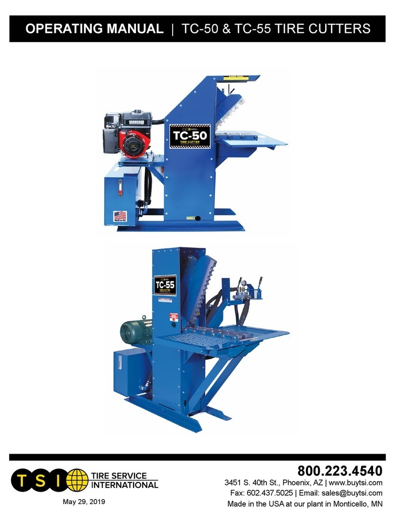
TSI Instruments TC-125 User manual

buyTSI.com - 800.223.4540
Contact us for any assistance
800.223.4540
Tire Service International, LLC
3451 S. 40TH ST.
PHOENIX, AZ 85040
Office: 602.437.5020
Fax: 602.437.5025
Read this manual before operating
TC-125
TIRE CUTTER
Revised: January 2022

buyTSI.com - 800.223.4540
1. Only personnel trained in the TC-125 should be operating this machine.
2. Throughly read all safety and operating instructions before using this machine.
3. Personal Protective Equipment must be used including safety glasses.
4. Never wet the engine, ignition switch or hydraulic controls. Cover these items, if machine is to
be washed.
5. Always disconnect electrical power from battery before attempting any maintenance.
6. Engine needs to be run outside for cooling and exhaust.
Safety Requirements
Installation Requirements
Set-Up Instruction
Operating Instruction
1. The machine instrument panel includes the key switch along with indicator lights. Turning the
key to the right activates the digital display. Follow on-screen directions for starting.
2. Throttle control increases or decreases engine speed. DO NOT operate beyond 3/4 throttle
speed.
1. The hydraulic oil reservoir should be lled 2 to 3 inches from the top. If you add or change the
uid, use Type A automatic transmission uid.
2. Position leveling jacks as required by raising or lowering jacks on either side to level the
machine.
3. For towing the TC-125, connect to a 2-5/16” diameter ball hitch. Connect electrical wires to
a wiring assembly to activate the electric brakes. Once connected, raise leveling jacks to their
highest point before moving.
1. Fuel for engine

buyTSI.com - 800.223.4540
Operating Instruction (continued)
1. Operating control levers - The left lever controls the shear arm. The center lever controls the
tire push/pull bars. The right lever controls the tire lift.
2. Insert the hydraulic push/pull bars into their sockets.
Adjust length as required for tire width, either by the
ball detent pin or with the adjusting cap screw.
3. Position stop arms on the lift as required.
4. Insert ball detent pin into stop arm pin holes.
Truck Tire Cutting Instruction
1. With arms positioned as shown, roll tire on hydraulic tire lift pad.
2. Start engine by following engine operating instructions.
3. By operating tire lift control lever on the right, the tire is raised to the
cutting table.
4. Tip tire up and over to positioned in the center of the cutting table.
5. Using center hydraulic control lever, move tire push/pull bars rmly
against the tire. By operating the lever on the left, move shear arm
down to begin the shearing process.
6. Continue to shear tire all the way through. Some additional adjustment may be done to the
push/pull bars during the shearing to maintain pressure or position on the tire.
7. NOTE: Tire debris may be deposited below the cutting table during normal shearing
operation. Before the next tire is placed onto the cutting table, ensure all of the cut debris is
removed from machine.
8. Reposition the push/pull bars after the shear blade returns to the up position. Then
reposition both of the tire halves and shear through them both.
9. Complete shearing the tire halves. When completed return the shear blade to the up position
and the push/pull bars rearward to the start position. Remove the cut pieces from the cutting
table.

buyTSI.com - 800.223.4540
Large Tire Cutting Instruction
1. Remove arms from sockets.
2. Position push/pull bars as shown here for a large tire.
3. Roll the tire onto the tire lift.
4. Support the top end of the tire on the push/pull bars.
5. Operate hydraulic lift to raise the tire to the cutting table. The tire
should drop over the push/pull bars once raised horizontally.
6. Using push/pull bars draw tire onto the cutting table.
7. Position push/pull bars against the inside lip of the tire. Do not press
the push/pull bars rmly as some adjustment may be required during
shearing process.
8. By using the tire cut lever on the left begin to shear tire.
9. Continue to shear tire, making adjustments to the push/pull bars as
required.
10. Push/pull bars are moved rearward to ease rotation of the tire for
the next shear.
11. With the shear blade up and the push/pull bars moved rearward, rotate tire on roller bed to
the next desired cutting point. Shear tire into smaller sections by repeating.
12. NOTE: Tire debris may be deposited below the cutting table during normal shearing
operation. Before the next tire is placed onto the cutting table, ensure all of the debris is removed
from the machine.

buyTSI.com - 800.223.4540
1. Grease main pivot bearings once a week. There is one bearing on each side of the machine.
2. Grease cylinder pivot anchors on both ends of the cylinder.
3. Grease all other pivot shafts on TC-125 (12 total)
4. Replace hydraulic lter element every six months or more frequently under heavy use or in
dusty climate conditions. Disassemble the 6 cap screws on top of lter assembly. Remove lter
element slowly allowing uid to drain. Replace with a new element. Replace lter cap and 6 cap
screws.
5. NOTE: Fluid should be changed completely every two years or if contaminated by foreign
matter. Filter should be replaced when uid is changed.
6. Follow manufacturers engine instruction manual for all engine service recommendations.
7. Zero Clearance adjustment procedure - With the shear blade in the full down position and the
engine off, loosen the cap screws on bed shear bars (both sides). By checking at various positions
adjust allen cap screws from both sides to adjust shear bars to a zero
clearance. Retighten bed cap screws.
8. Every six months or prior to towing, remove wheels and inspect hub
assemblies. Disassemble the wheel hub assembly and pack grease into
wheel bearings and seals if required.
Maintinance

buyTSI.com - 800.223.4540
Replacement Parts List
Item Description
4378 Cylinder 2 x 6
4857 Cylinder 2.5 x 16
3830 Cylinder 6 x 48
4619F Female Shear Blade (two on bottom)
10171 Gauge, Sight for Reservoir
3019-4000 Gauge, 2.5 Dia x 1/4 NPT
3851 Jack, Sidewind 7,000lb
4618 Male Shear Blade (top)
4389 Needle Valve 3,000psi
10020A Oil Filter Assembly
10152-12V Oil Cooler Assembly
4617 Pin, Fulcrum 2.5 Dia x 17
4622 Pin, 1.5 Dia x 6
10642 Pin, 1.5 Dia x 11.25
4819 Pump, Gear Hydraulic
4823 Valve, 3 spool 45 GPM
1444 Wheel & Tire Assembly 4.10 x 3.5 x 4

buyTSI.com - 800.223.4540
Specication
Size: 192”L x 72”W x 100”H
Weight: 6,800 lbs
Power: Diesel - 49.6 hp Kubota
Cylinder Bore &
Stroke:
6”x 48” with 79,168 lbs of force
Pull Cylinder: 2.5” x 16”
Li Cylinder: 2” x 6”
Hydraulic Oil: 29 gallon SAE 20 or 30 Automatic
Transmission Fluid
System Pressure: 2,800 psi maximum
Pump: 45 gpm
Additional Notes:

buyTSI.com - 800.223.4540
Visit www.buyTSI.com for any additional information. Also be sure to follow us on all the Socials, and
subscribe to our YouTube channel for all our product videos.
Warranty & Workmanship you can depend on.
With over 30 years of manufacturing experience we maintain the ability to provide competitive
prices while employing and manufacturing the majority of our products in the USA. Pride in
our workmanship and standing behind each and every product is not just our claim but our
uncompromising responsibility.
Tire Service International equipment is warranted to be free from defects in materials and
workmanship for a period of one year from the date of original purchase to the original owner.
Repair labor is warranted for 90 days from the date of original purchase. Bushings, blades, bearings
and normal wear and tear are not covered under warranty. Careless handling, negligence, misuse,
abuse, mutilation, improper operation, making unauthorized repairs, additions, and or alterations
automatically cancel this warranty and relieves TSI of any obligation. Cheetah tanks claimed to be
defective while under warranty will be evaluated at our manufacturing plant and either repaired
if possible or exchanged and returned or credit issued to the customer account at our discretion.
Damage resulting from dropping the tanks will not receive warranty consideration. Warranty parts
need to be returned prepaid to the plant for credit. Any replacement parts shipped from the plant
will be shipped at the customer's expense. Machines requiring warranty work must be brought to
the manufacturing plant in 201 Chelsea Rd, Monticello, MN or to a repair facility authorized by TSI.
!!WARNING!! Goods returned without an RGA will be refused. A Returned Goods Authorization
form must be obtained before returning any material or goods. All non-warranty returns will be
subject to a 15% restocking fee plus any additional charges for reconditioning/repacking.
Warranty and Return Policy
Copyright © 2021 Tire Service International, LLC
No part of this manual may be reproduced without
specic approval from Tire Service International, LLC.
Table of contents
Other TSI Instruments Cutter manuals