TSO Products TPG PARALLEL GUIDE SYSTEM User manual

USER GUIDE FOR TPG SYSTEM
Publication 699-009 RevH ©2022 TSO Products LLC Page 1 of 2
when changing between narrow cut and standard calibration rods.
Connecting TPG T-Tracks to your
guide rail can be accomplished using
either a GRS-16 Guide Rail Square,
GRS-16 PE Guide Rail Square, or TPG
Adapter. Either two TPG Adapters can
be used; or one TPG Adapter and one
GRS-16 Guide Rail Square; or two GRS-
16 Guide Rail Squares (one of which must be a GRS-16 PE for the
left-hand T-Track, as it is the only square capable of referencing off
the front or back edge of your workpiece).
CALIBRATION: FOR FINISHED PARTS WIDER THAN
GUIDE RAIL
1. Mount the TPG Parallel Guide T-Track to the GRS-16 Guide
Rail Square or TPG Adapter using the (2) M6 x 10 mm knobs
provided.
2. Slide the FlipStop onto the TPG Parallel Guide T-Track, cursor
end rst, and tighten (secure) the knob.
3. Attach the GRS-16 Square + Parallel Guide assembly to the Fes-
tool, or Makita or Triton guide rail as shown.
If you own a combination square, skip to step 8.
4. Mark a line on the workpiece at 10 inches (254mm) from the
edge.
5. Place the assembled Guide Rail + GRS-16 Square + Parallel
Guide on the workpiece and set the cursor to the 10-inch
(254mm) mark.
6. Loosen the Screw securing the Calibration Rod and slide the rod
so that it contacts the edge of the workpiece. Then tighten the
screw securely with the 3mm hex driver provided.
7. This calibration should be complete for this saw and guide rail
combination, but cuts should be checked occasionally to con-
rm nothing has changed.
Thanks for purchasing this genuine TSO Product. Should you have
any product questions or issues, please contact us toll-free at 800-727-
0311 (U.S.), 239-236-5526 (international), email us at info@tsoprod-
ucts.com, or visit www.tsoproducts.com/support for the most up-to-date
version of this user guide.
INTRODUCTION
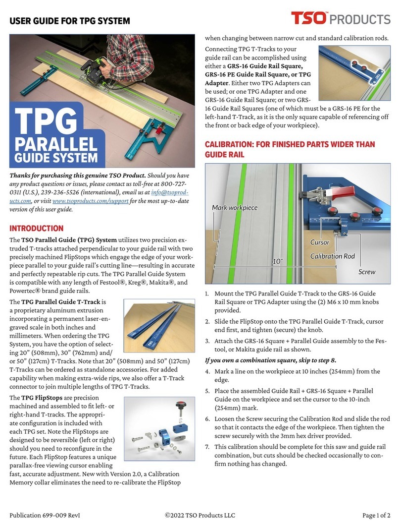
The TSO Parallel Guide (TPG) System utilizes two precision
extruded T-tracks attached perpendicular to your guide rail with
two precisely machined FlipStops which engage the edge of your
workpiece parallel to your guide rail’s cutting line—resulting in
accurate and perfectly repeatable rip cuts. The TPG Parallel Guide
System is compatible with any length of Festool®, Kreg®, Maki-
ta®, Powertec® and Triton® brand guide rails.
The TPG Parallel Guide T-Track is
a proprietary aluminum extrusion
incorporating a permanent laser-en-
graved scale in both inches and
millimeters. When ordering the TPG
System, you have the option of select-
ing 20” (508mm), 30” (762mm) and/
or 50” (127cm) T-Tracks. Note that 20” (508mm) and 50” (127cm)
T-Tracks can be ordered as standalone accessories. For added
capability when making extra-wide rips, we also offer a T-Track
connector to join multiple lengths of TPG T-Tracks.
The TPG FlipStops are precision
machined and assembled to t left- or
right-hand T-tracks. The appropri-
ate conguration is included with
each TPG set. Note the FlipStops are
designed to be reversible (left or right)
should you need to recongure in the
future. Each FlipStop features a unique
parallax-free viewing cursor enabling
fast, accurate adjustment. New with Version 2.0, a Calibration
Memory collar eliminates the need to re-calibrate the FlipStop
TPG
PARALLEL
GUIDE SYSTEM

USER GUIDE FOR TPG SYSTEM
Publication 699-009 RevH ©2022 TSO Products LLC Page 2 of 2
CALIBRATION: FOR FINISHED PARTS WIDER THAN
GUIDE RAIL (CONTINUED)
If you have a combination square…
8. Set your combination square to 10 inches (254mm) and place
the 90° face of the combination square at against the guide
rail splinter guard.
9. Extend or retract the Calibration Rod to touch the tip of the
combination square blade. Ensuring the combination square is
still at against the guide rail splinter guard, secure the Calibra-
tion Rod with the 3mm hex driver provided.
USE: FOR FINISHED PARTS WIDER THAN GUIDE RAIL
1. Conrm that nished part will be wider than the guide rail.
2. Set the cursor on the TPG Parallel Guide to the required width
of cut.
3. Set the saw to the required depth of cut.
4. Position the reference edge of the GRS-16 Guide Rail Square
against the edge of the workpiece perpendicular to the cuT.
5. Move the Parallel Guide + Guide Rail so that the head of the
Calibration Rod rests against the edge of the workpiece which
will be parallel to the cut.
6. It may be helpful to raise the guide rail slightly to ease the fric-
tion caused by its anti-slip strips and make it easier to reposi-
tion.
CALIBRATION: FOR FINISHED PARTS NARROWER
THAN GUIDE RAIL
This calibration process requires use of the supplied Narrow Part
Rod. It is the longer of the two calibration rods included in your
TPG Set.
Although the TPG System, as with all parallel guide devices, can be used
to cut narrow parts (narrower than the guide rail), the preferred method
of making narrow part cuts is with a table saw. Extra care must be used
to make a stable setup. We recommend practicing with scrap material to
perfect your technique.
Cutting narrow parts requires using both the left- and right-hand
parallel guides. Additionally, the workpiece must be supported
with pieces of material under the guide rail of the same thickness
as the workpiece to stabilize the Guide Rail + GRS-16 Square +
Parallel Guide assembly and prevent the workpiece from moving
while being cut. This is even more important when the workpiece
is shorter than the guide rail being used.
1. Mount the TPG Parallel Guide T-Track to the GRS-16 Guide
Rail Square or TPG Adapter using the (2) M6 x 10 mm knobs
provided.
2. Slide the FlipStop onto the TPG Parallel Guide T-Track, cursor
end rst.
3. Attach the GRS-16 Square + Parallel Guide assembly to the right
end of the Festool, Makita, or Triton guide rail.
4. Remove the Standard Calibration Rod (used for wide parts) and
insert the Narrow Part Rod.
5. Place the assembled Guide Rail + GRS-16 Square + Parallel
Guide on the workpiece with the Narrow Part Rod under the
Guide Rail and set the cursor to the 10” (254 mm) mark.
6. Place a piece of material against the Guide Rail splinter guard.
Loosen the screw securing the Narrow Part Rod and slide the
rod so that it contacts the edge of the material in contact with
the splinter guard. Then tighten the screw securely with the 3
mm hex driver provided.
7. With this calibration method, zero-width corresponds to the
10” (254 mm) mark. As an example, to cut material 3” wide, the
cursor would be set to the 13” (330 mm) mark.
8. This calibration should be complete for this saw and guide
rail combination, but cuts should be
checked occasionally to conrm noth-
ing has changed.
For a video walkthrough of calibrating the
TPG System, visit the TPG System product
page at tsoproducts.com.
From the entire TSO Team, we wish you enjoyable use of this
product. Please swing by our website and leave a review if you
get a moment—it really makes a difference.
Other TSO Products Tools manuals
