TSURUGA ELECTRIC NRP-60 User manual
TSURUGA ELECTRIC CORPORATION
4-φ4
24 24
57
2424
Instruction Manual
Meter Relay Model NRP-60
I-01899-1/2
We thank you for your purchase of our model NRP-60 series meter relay. For safety use of this product, please observe the
following caution. For proper operation of it, please also read the instructions to follow before the initial operation.
CAUTION
To prevent electric shock, observe the following cautions:
◆ Never make power line connections with active lines.
◆ Ensure firm and tight connections to the terminals.
◆ Do not touch the power source terminals while the
instrument is powered on.
To avoid electric shock, failure or abnormal heat-up of the
instrument, do not use the instruments in such places where:
◆ exposed to rain, water drops or direct sunlight.
◆ high temperature or humidity, much dust or corrosive gas.
◆ affected by external noise, radio waves or static electricity.
◆ where there is constant vibration shock.
■ Check at Delivery
When the product is delivered to you, please check that its specifications conform to your requirement and that there is no damage in
transit. This instrument is carefully inspected before delivery from factory under our strict quality control program, but if you find
any defect or inconvenience, please inform us of the model name and serial number of the product, etc.
■ Cautions for Use
① This product is a precision instrument, so please take utmost care for transportation, installation or any other handling of it.
② No power on-off switch is provided on this product, so it immediately starts to operate when connected to the power source.
③ In case of fear that the external noise of surge may cause malfunction or breakdown of this instrument, it is necessary to take
proper protective solution against noise.
④ In case of fear that this instrument suffers the surge voltage, ground one side of the measuring input terminals.
⑤ Use this product within the range or conditions conforming to its specifications and standard.
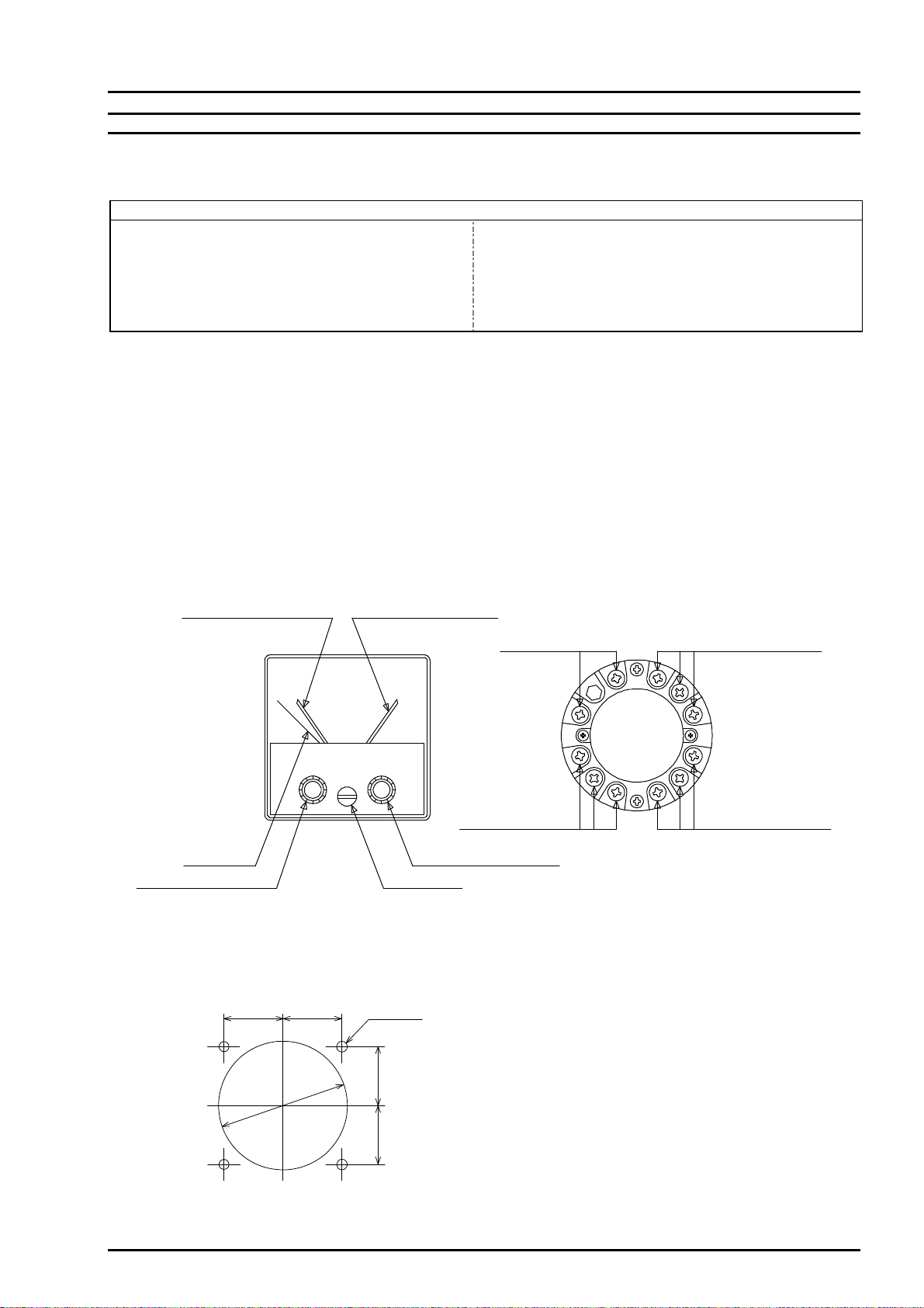
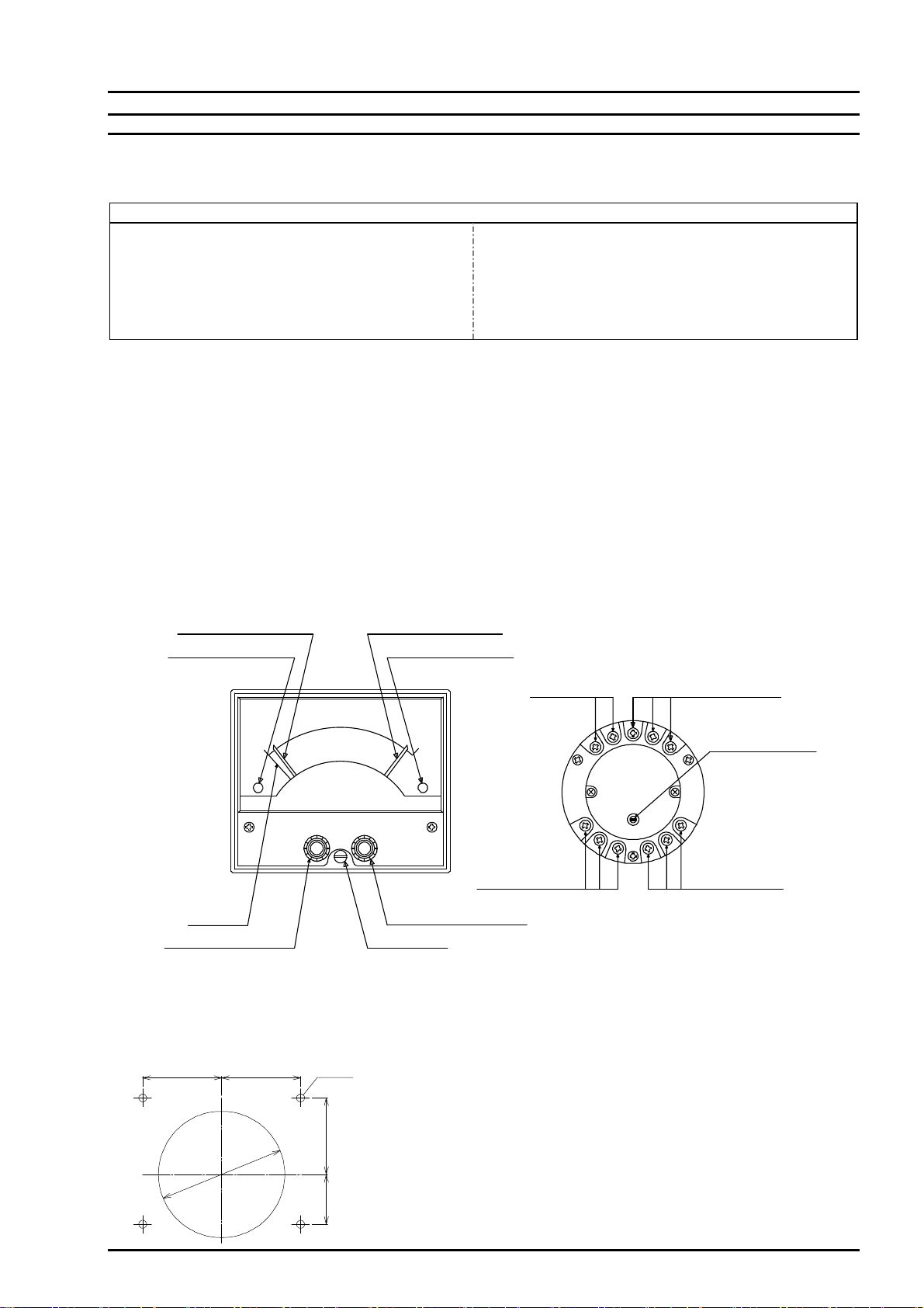
■ Name of Parts
Note: In case that the model name is NRP-60H, no low limit setting lever, set point
index bar ,low limit display or contact output terminal is provided.
■ Panel Cut-Out Dimensions
■ Installation
Insert the instrument from the front of the panel to install.
And fasten them with the mounting screw to the pane
Optimum fastening torque : 0.36~0.48N・m
[Note]
Output terminal
low limit contact
Output terminal
high limit contact
Auxiliary supply terminals
Measuring
input terminal
Low limit setting index High limit setting index
High limit setting knob
Measuring
Low limit setting knob Zero adjuster
pointer
Model NRP-60
I-01899- 2/2
TSURUGA ELECTRIC CORPORATION
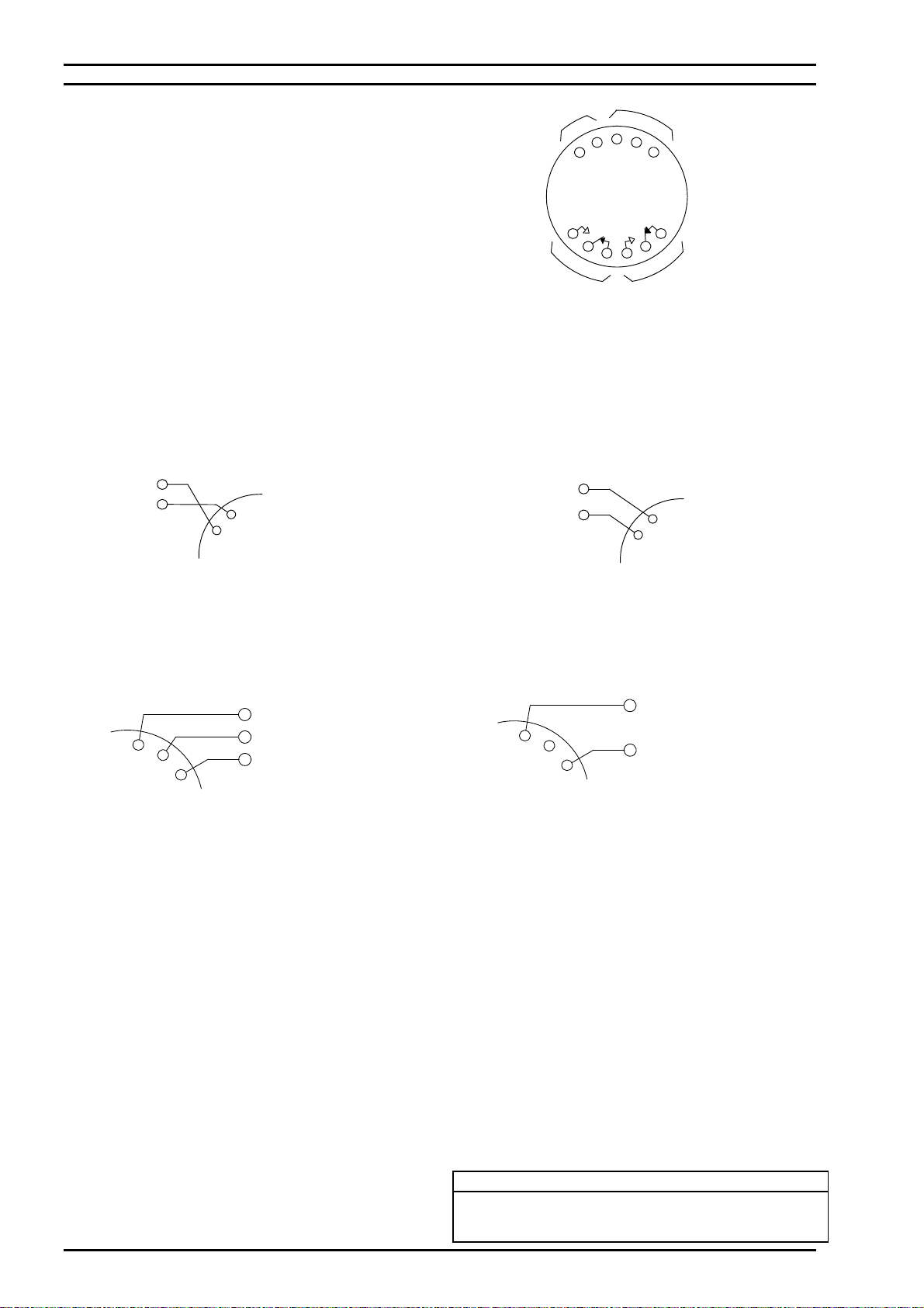
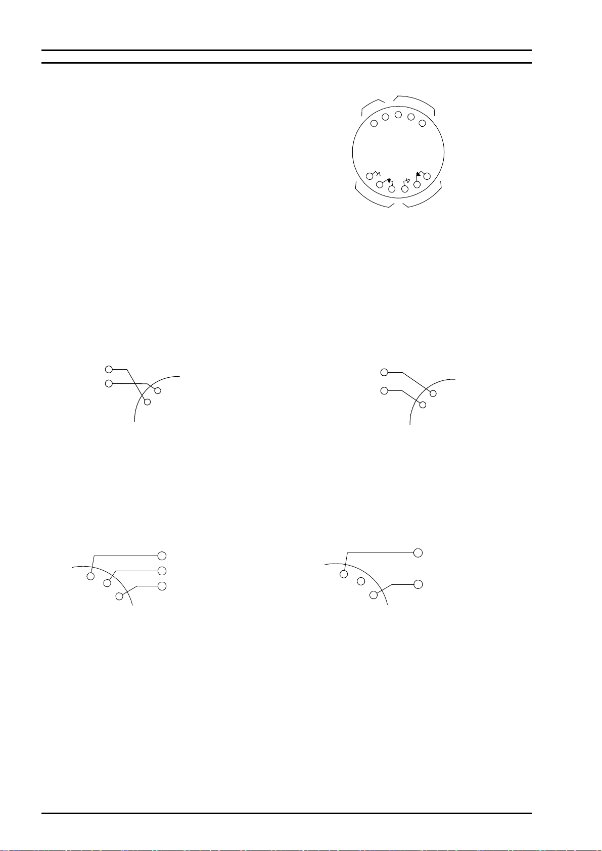
■ Connections
Measuring input terminals of the instrument and,
the contact output and auxiliary supply terminals M3.
Make firm and correct connections with crimp type terminal.
Optimum torque of the terminal screws: 0.36~0.48N・m
Note : In case that the model name is NRP-60H, no contact output
terminals for the low limit is provided.
● Measuring Input Terminals
Arrange a cabling of measuring input line and power source line as distant as possible from each other. Close and parallel wiring of
these two lines may cause unstable reading of the instrument.
① DC Volt Meter
DC Current Meter
Receiving Meter
Connect the measuring input with correct polarity.
Use the particular accessory when it is designated.
② AC Volt Meter
AC Current Meter
Connect the measuring input.
Use the particular accessory when it is designated.
● Auxiliary supply Terminals
① AC power source model ② DC power source model
Connect the AC voltage to the respective terminals of Connect the DV24V to the auxiliary supply
auxiliary supply terminals (SOURCE). terminals (SOURCE) with correct polarity.
AC100V power source voltage: Terminals ± and 100/110V
AC200V power source voltage: Terminals ± and 200/220V
● High Limit (HIGH) and Low Limit (LOW) Contact Output Terminals
The contact capacity of high and low limit contact output is, with resistive load: AC250V, 125VA or DC30V, 60W
Make the connections with the cable conforming to these capacities. In case that the relay controls with the capacity higher than
these, provide the auxiliary relay externally.
■ Operation
① Prior to the operation of instrument, check that the input rate, auxiliary supply voltage and connections are correct.
② Before starting the measurement, check if the measuring pointer is accurately at zero (which is the point when the DC4mA
or DC1V generated by a standard voltage/current generator is input to the input terminals, respectively when the rated input
is DC4~20mA or DC1~5V). If there is a discrepancy at zero, adjust the pointer to indicate zero with the adjuster provided
on the front of the instrument.
③ Turning the high (or low) limit setting knob, set the setting index at a desired point where the relay acts.
The setting index stops at slightly beyond the scaled range. If the setting knob is forcedly turned more, it causes a breakage,
so take care with it.
Note)
When the input impedance at the input rating DC1 ~ 5V with the specification of 7331 accessory having more than 1 MΩ is
inserted the auxiliary power with opened condition of input terminal of 7331, the measuring pointer indicates more than the
upper limit of the scale.
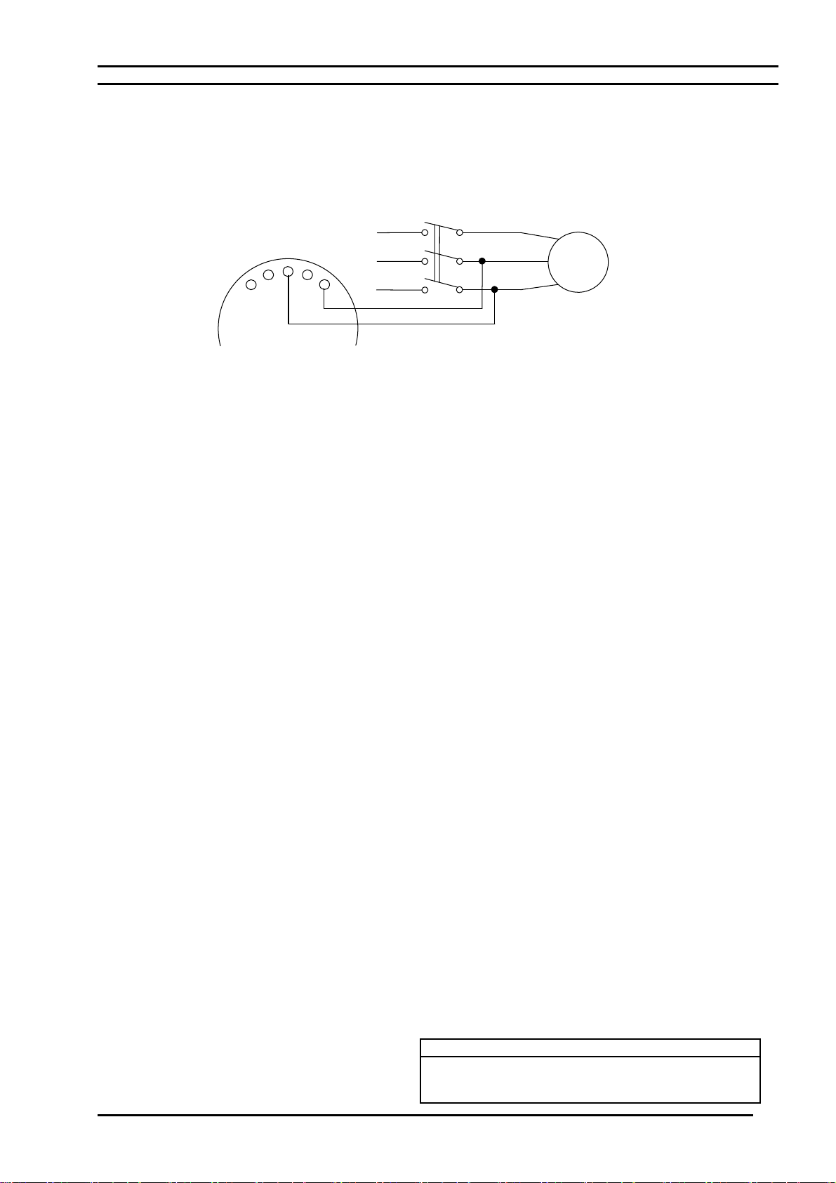
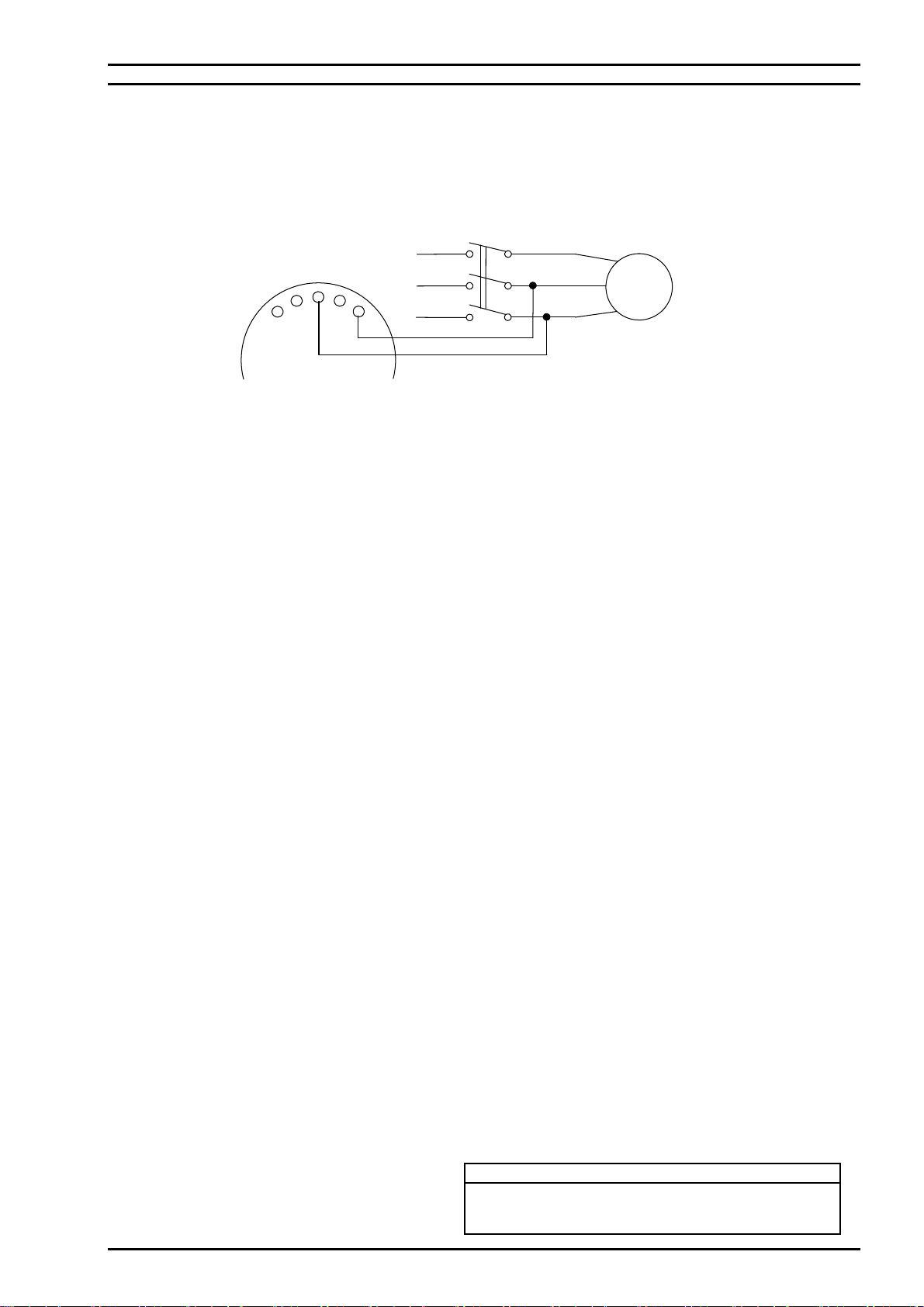
④ While the instrument is powered on and when the measuring pointer exceeds the setting index (set point), the relay is
actuated and, a-c turns ON (close) and c-b turns OFF (open).
HIGH
LOW
M
SOURCE
a
c
b
a
c
b
Output terminal
[Note]
low limit contact
Output terminal
high limit contact
Measuring
input terminal supply terminals
Auxiliary
AC INPUT
INPUT
AC
M(-)
M
(+)(-)
(+)
SOURCE
200V(220V)±10%
100V(110V)±10%
±
SOURCE
DC24V±10%
+
-
Contact Information
Name : Tsuruga Electric Corporation
Address : 1-3-23 Minami-Sumiyoshi, Sumiyoshi-ku, Osaka-shi
558-0041 Japan

Instruction Manual
Meter Relay Model NRP-83
I-01972 1/3
TSURUGA ELECTRIC CORPORATION
80
4-φ4
34 34
3434
We thank you for your purchase of our model NRP-83 series meter relay. For safety use of this product, please observe the
following caution. For proper operation of it, please also read the instructions to follow before the initial operation.
CAUTION
To prevent electric shock, observe the following cautions:
◆ Never make power line connections with active lines.
◆ Ensure firm and tight connections to the terminals.
◆ Do not touch the power source terminals while the
instrument is powered on.
To avoid electric shock, failure or abnormal heat-up of the
instrument, do not use the instruments in such places where:
◆ exposed to rain, water drops or direct sunlight.
◆ high temperature or humidity, much dust or corrosive gas.
◆ affected by external noise, radio waves or static electricity.
◆ where there is constant vibration shock.
■ Check at Delivery
When the product is delivered to you, please check that its specifications conform to your requirement and that there is no damage in
transit. This instrument is carefully inspected before delivery from factory under our strict quality control program, but if you find
any defect or inconvenience, please inform us of the model name and serial number of the product, etc.
■ Cautions for Use
① This product is a precision instrument, so please take utmost care for transportation, installation or any other handling of it.
② No power on-off switch is provided on this product, so it immediately starts to operate when connected to the power source.
③ In case of fear that the external noise of surge may cause malfunction or breakdown of this instrument, it is necessary to take
proper protective solution against noise.
④ In case of fear that this instrument suffers the surge voltage, ground one side of the measuring input terminals.
⑤ Use this product within the range or conditions conforming to its specifications and standard.
■ Name of Parts
Note: In case that the model name is NRP-83H, no low limit setting lever, set point
index bar ,low limit display or contact output terminal is provided.
■ Panel Cut-Out Dimensions
■ Installation
Insert the instrument from the front of the panel to install.
And fasten them with the mounting screw to the pane
Optimum fastening torque : 0.36~0.48N・m
input terminal
Measuring
Auxiliary supply terminals
high limit contact
Output terminal low limit contact
Output terminal
[Note]
(option)
for span adjustment
Variable resister
pointer
Measuring
Low limit setting index
High limit LED display
High limit setting index
Low limit LED display
High limit setting knob
Zero adjuster
Low limit setting knob

Model NRP-83
I-01972 2/3
TSURUGA ELECTRIC CORPORATION
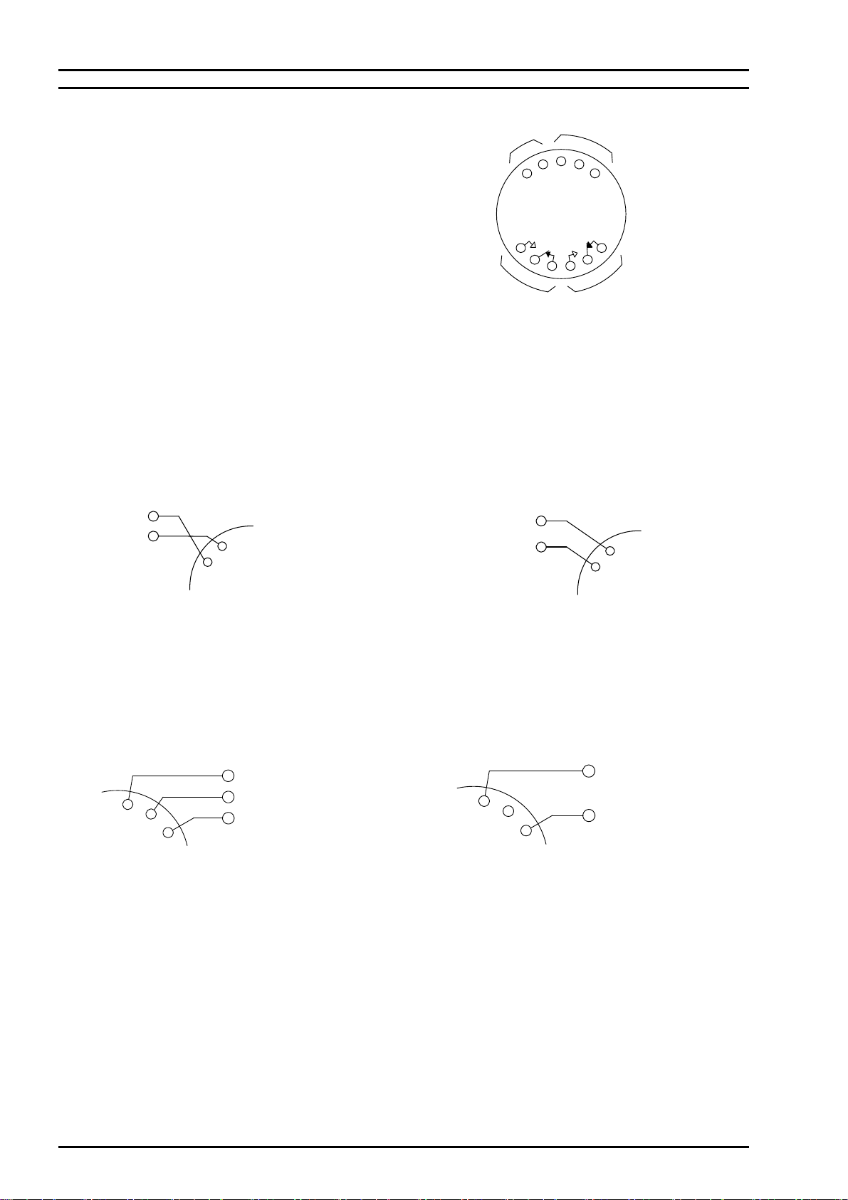
■ Connections
Measuring input terminals of the instrument and,
the contact output and auxiliary supply terminals M3.
Make firm and correct connections with crimp type terminal.
Optimum torque of the terminal screws: 0.36~0.48N・m
Note : In case that the model name is NRP-83H, no contact output
terminals for the low limit is provided.
● Measuring Input Terminals
Arrange a cabling of measuring input line and power source line as
distant as possible from each other. Close and parallel wiring of these
two lines may cause unstable reading of the instrument.
① DC Volt Meter
DC Current Meter
Receiving Meter
Connect the measuring input with correct polarity.
Use the particular accessory when it is designated.
② AC Volt Meter
AC Current Meter
Connect the measuring input.
Use the particular accessory when it is designated.
● Auxiliary supply Terminals
① AC power source model ② DC power source model
Connect the AC voltage to the respective terminals of Connect the DV24V to the auxiliary supply
auxiliary supply terminals (SOURCE). terminals (SOURCE) with correct polarity.
AC100V power source voltage: Terminals ± and 100/110V
AC200V power source voltage: Terminals ± and 200/220V
● High Limit (HIGH) and Low Limit (LOW) Contact Output Terminals
The contact capacity of high and low limit contact output is, with resistive load: AC250V, 3A or DC30V, 3A
Make the connections with the cable conforming to these capacities. In case that the relay controls with the capacity higher than
these, provide the auxiliary relay externally.
HIGH
LOW
M
SOURCE
a
c
b
a
c
b
Output terminal
[Note]
low limit contact
Output terminal
high limit contact
Measuring
input terminal supply terminals
Auxiliary
AC INPUT
INPUT
AC
M(-)
M
(+)(-)
(+)
SOURCE
200V(220V)±10%
100V(110V)±10%
±
SOURCE
DC24V±10%
+
-
Model NRP-83
I-01972 3/3
TSURUGA ELECTRIC CORPORATION
■ Optional specification
○Power on delay circuit (-T2, -T5, -T10)
The power on delay circuit is synchronized with the turning on of the meter relay, so the power has to be supplied from the
measurement line.
(Delay time: -T2: 2 seconds, -T5: 5 seconds, -T10: 10 seconds)
■ Operation
① Prior to the operation of instrument, check that the input rate, auxiliary supply voltage and connections are correct.
② Before starting the measurement, check if the measuring pointer is accurately at zero (which is the point when the DC4mA
or DC1V generated by a standard voltage/current generator is input to the input terminals, respectively when the rated input
is DC4~20mA or DC1~5V). If there is a discrepancy at zero, adjust the pointer to indicate zero with the adjuster provided
on the front of the instrument.
Note)
When the input impedance at the input rating DC1 ~ 5V with the specification of 7331 accessory having more than 1 MΩ is
inserted the auxiliary power with opened condition of input terminal of 7331, the measuring pointer indicates more than the
upper limit of the scale.
③ Turning the high (or low) limit setting knob, set the setting index at a desired point where the relay acts.
The setting index stops at slightly beyond the scaled range. If the setting knob is forcedly turned more, it causes a breakage,
so take care with it.
④ While the instrument is powered on and when the measuring pointer exceeds the setting index (set point), the relay is
actuated and, a-c turns ON (close) and c-b turns OFF (open).
■ Calibration
When the variable resistor for span adjustment is provided, calibrate the instrument at an interval of about one year in order to
maintain long term accuracy. The calibration can be done with the zero adjuster provided on the panel front and the variable
resistor for span adjustment on the rear of the instrument. Make the calibration with the ambient condition of 23oC±5oC and
75%RH or less.
Motor
Power
SOURCE
supply
Contact Information
Name : Tsuruga Electric Corporation
Address : 1-3-23 Minami-Sumiyoshi, Sumiyoshi-ku, Osaka-shi
558-0041 Japan

TSURUGA ELECTRIC CORPORATION
32 32
80
40 40 4-φ4
Instruction Manual
Meter Relay Model NRC-100
I-01758-1/3
We thank you for your purchase of our model NRC-100 series meter relay. For safety use of this product, please observe the
following caution. For proper operation of it, please also read the instructions to follow before the initial operation.
CAUTION
To prevent electric shock, observe the following cautions:
◆ Never make power line connections with active lines.
◆ Ensure firm and tight connections to the terminals.
◆ Do not touch the power source terminals while the
instrument is powered on.
To avoid electric shock, failure or abnormal heat-up of the
instrument, do not use the instruments in such places where:
◆ exposed to rain, water drops or direct sunlight.
◆ high temperature or humidity, much dust or corrosive gas.
◆ affected by external noise, radio waves or static electricity.
◆ where there is constant vibration shock.
■ Check at Delivery
When the product is delivered to you, please check that its specifications conform to your requirement and that there is no damage in
transit. This instrument is carefully inspected before delivery from factory under our strict quality control program, but if you find
any defect or inconvenience, please inform us of the model name and serial number of the product, etc.
■ Cautions for Use
① This product is a precision instrument, so please take utmost care for transportation, installation or any other handling of it.
② No power on-off switch is provided on this product, so it immediately starts to operate when connected to the power source.
③ In case of fear that the external noise of surge may cause malfunction or breakdown of this instrument, it is necessary to take
proper protective solution against noise.
④ In case of fear that this instrument suffers the surge voltage, ground one side of the measuring input terminals.
⑤ Use this product within the range or conditions conforming to its specifications and standard.
■ Name of Parts
Note: In case that the model name is NRC-100H, no low limit setting lever, set point
index bar ,low limit display or contact output terminal is provided.
■ Panel Cut-Out Dimensions
■ Installation
Insert the instrument from the front of the panel to install.
And fasten them with the mounting screw to the pane
Optimum fastening torque : 0.36~0.48N・m
input terminal
Measuring
Auxiliary supply terminals
high limit contact
Output terminal low limit contact
Output terminal
[Note]
(option)
for span adjustment
Variable resister
pointer
Measuring
Low limit setting knob
High limit setting knob
Zero adjuster
High limit LED display
High limit setting index
Low limit LED display
Low limit setting index
Model NRC-100
I-01758- 2/3
TSURUGA ELECTRIC CORPORATION
■ Connections
Measuring input terminals of the instrument and,
the contact output and auxiliary supply terminals M3.
Make firm and correct connections with crimp type terminal.
Optimum torque of the terminal screws: 0.36~0.48N・m
Note : In case that the model name is NRC-100H, no contact output
terminals for the low limit is provided.
● Measuring Input Terminals
Arrange a cabling of measuring input line and power source line as
distant as possible from each other. Close and parallel wiring of these
two lines may cause unstable reading of the instrument.
① DC Volt Meter
DC Current Meter
Receiving Meter
Connect the measuring input with correct polarity.
Use the particular accessory when it is designated.
② AC Volt Meter
AC Current Meter
Connect the measuring input.
Use the particular accessory when it is designated.
● Auxiliary supply Terminals
① AC power source model ② DC power source model
Connect the AC voltage to the respective terminals of Connect the DV24V to the auxiliary supply
auxiliary supply terminals (SOURCE). terminals (SOURCE) with correct polarity.
AC100V power source voltage: Terminals ± and 100/110V
AC200V power source voltage: Terminals ± and 200/220V
● High Limit (HIGH) and Low Limit (LOW) Contact Output Terminals
The contact capacity of high and low limit contact output is, with resistive load: AC250V, 3A or DC30V, 3A
Make the connections with the cable conforming to these capacities. In case that the relay controls with the capacity higher than
these, provide the auxiliary relay externally.
HIGH
LOW
M
SOURCE
a
c
b
a
c
b
Output terminal
[Note]
low limit contact
Output terminal
high limit contact
Measuring
input terminal supply terminals
Auxiliary
AC INPUT
INPUT
AC
M(-)
M
(+)(-)
(+)
SOURCE
200V(220V)±10%
100V(110V)±10%
±
SOURCE
DC24V±10%
+
-
Model NRC-100
I-01758- 3/3
TSURUGA ELECTRIC CORPORATION
■ Optional specification
○Power on delay circuit (-T2, -T5, -T10)
The power on delay circuit is synchronized with the turning on of the meter relay, so the power has to be supplied from the
measurement line.
(Delay time: -T2: 2 seconds, -T5: 5 seconds, -T10: 10 seconds)
■ Operation
① Prior to the operation of instrument, check that the input rate, auxiliary supply voltage and connections are correct.
② Before starting the measurement, check if the measuring pointer is accurately at zero (which is the point when the DC4mA
or DC1V generated by a standard voltage/current generator is input to the input terminals, respectively when the rated input
is DC4~20mA or DC1~5V). If there is a discrepancy at zero, adjust the pointer to indicate zero with the adjuster provided
on the front of the instrument.
Note)
When the input impedance at the input rating DC1 ~ 5V with the specification of 7331 accessory having more than 1 MΩ is
inserted the auxiliary power with opened condition of input terminal of 7331, the measuring pointer indicates more than the
upper limit of the scale.
③ Turning the high (or low) limit setting knob, set the setting index at a desired point where the relay acts.
The setting index stops at slightly beyond the scaled range. If the setting knob is forcedly turned more, it causes a breakage,
so take care with it.
④ While the instrument is powered on and when the measuring pointer exceeds the setting index (set point), the relay is
actuated and, a-c turns ON (close) and c-b turns OFF (open).
■ Calibration
When the variable resistor for span adjustment is provided, calibrate the instrument at an interval of about one year in order to
maintain long term accuracy. The calibration can be done with the zero adjuster provided on the panel front and the variable
resistor for span adjustment on the rear of the instrument. Make the calibration with the ambient condition of 23oC±5oC and
75%RH or less.
Motor
Power
SOURCE
supply
Contact Information
Name : Tsuruga Electric Corporation
Address : 1-3-23 Minami-Sumiyoshi, Sumiyoshi-ku, Osaka-shi
558-0041 Japan
TSURUGA ELECTRIC CORPORATION
48.531.5
φ80
50 50 4-φ5
[Unit:mm]
Instruction Manual
Meter Relay Model NRC-120
I-02329-1/3
We thank you for your purchase of our model NRC-120 series meter relay. For safety use of this product, please observe the
following caution. For proper operation of it, please also read the instructions to follow before the initial operation.
CAUTION
To prevent electric shock, observe the following cautions:
◆Never make power line connections with active lines.
◆Ensure firm and tight connections to the terminals.
◆Do not touch the power source terminals while the
instrument is powered on.
To avoid electric shock, failure or abnormal heat-up of the
instrument, do not use the instruments in such places where:
◆exposed to rain, water drops or direct sunlight.
◆high temperature or humidity, much dust or corrosive gas.
◆affected by external noise, radio waves or static electricity.
◆where there is constant vibration shock.
■Check at Delivery
When the product is delivered to you, please check that its specifications conform to your requirement and that there is no damage
in transit. This instrument is carefully inspected before delivery from factory under our strict quality control program, but if you
find any defect or inconvenience, please inform us of the model name and serial number of the product, etc.
■Cautions for Use
① This product is a precision instrument, so please take utmost care for transportation, installation or any other handling of it.
② No power on-off switch is provided on this product, so it immediately starts to operate when connected to the power source.
③ In case of fear that the external noise of surge may cause malfunction or breakdown of this instrument, it is necessary to take
proper protective solution against noise.
④ In case of fear that this instrument suffers the surge voltage, ground one side of the measuring input terminals.
⑤ Use this product within the range or conditions conforming to its specifications and standard.
■Name of Parts
Note: In case that the model name is NRC-120H, no low limit setting lever, set point
index bar ,low limit display or contact output terminal is provided.
■ Panel Cut-Out Dimensions
■Installation
Insert the instrument from the front of the panel to install.
And fasten them with the mounting screw to the pane
Optimum fastening torque : 0.82~1.11 N・m
input terminal
Measuring
Auxiliary supply terminals
high limit contact
Output terminal low limit contact
Output terminal
[Note]
(option)
for span adjustment
Variable resister
pointer
Measuring
Low limit setting knob
High limit setting knob
Zero adjuster
High limit LED display
High limit setting index
Low limit LED display
Low limit setting index
Model NRC-120
I-02329- 2/3
TSURUGA ELECTRIC CORPORATION
■Connections
Measuring input terminals of the instrument and,
the contact output and auxiliary supply terminals M3.
Make firm and correct connections with crimp type terminal.
Optimum torque of the terminal screws: 0.36~0.48N・m
Note: In case that the model name is NRC-120H, no contact output
terminals for the low limit is provided.
●Measuring Input Terminals
Arrange a cabling of measuring input line and power source line as
distant as possible from each other. Close and parallel wiring of these
two lines may cause unstable reading of the instrument.
①DC Volt Meter
DC Current Meter
Receiving Meter
Connect the measuring input with correct polarity.
Use the particular accessory when it is designated.
②AC Volt Meter
AC Current Meter
Connect the measuring input.
Use the particular accessory when it is designated.
●Auxiliary supply Terminals
①AC power source model ②DC power source model
Connect the AC voltage to the respective terminals of Connect the DV24V to the auxiliary supply
auxiliary supply terminals (SOURCE). terminals (SOURCE) with correct polarity.
AC100V power source voltage: Terminals ±and 100/110V
AC200V power source voltage: Terminals ±and 200/220V
●High Limit (HIGH) and Low Limit (LOW) Contact Output Terminals
The contact capacity of high and low limit contact output is, with resistive load: AC 250V 3A, or DC 30V 3A
Make the connections with the cable conforming to these capacities. In case that the relay controls with the capacity higher than
these, provide the auxiliary relay externally.
HIGH
LOW
M
SOURCE
a
c
b
a
c
b
Output terminal
[Note]
low limit contact
Output terminal
high limit contact
Measuring
input terminal supply terminals
Auxiliary
AC INPUT
INPUT
C
A
M(-)
M
(+)(-)
(+)
SOURCE
200V(220V)±10%
100V(110V)±10%
±
SOURCE
DC24V±10%
+
-

Model NRC-120
I-02329- 3/3
TSURUGA ELECTRIC CORPORATION
■ Optional specification
○Power on delay circuit (-T2, -T5, -T10)
The power on delay circuit is synchronized with the turning on of the meter relay, so the power has to be supplied from the
measurement line.
(Delay time: -T2: 2 seconds, -T5: 5 seconds, -T10: 10 seconds)
■Operation
①Prior to the operation of instrument, check that the input rate, auxiliary supply voltage and connections are correct.
②Before starting the measurement, check if the measuring pointer is accurately at zero (which is the point when the DC4mA
or DC1V generated by a standard voltage/current generator is input to the input terminals, respectively when the rated input
is DC4~20mA or DC1~5V). If there is a discrepancy at zero, adjust the pointer to indicate zero with the adjuster provided
on the front of the instrument.
Note)
When the input impedance at the input rating DC1 ~ 5V with the specification of 7331 accessory having more than 1 MΩis
inserted the auxiliary power with opened condition of input terminal of 7331, the measuring pointer indicates more than the
upper limit of the scale.
③ Turning the high (or low) limit setting knob, set the setting index at a desired point where the relay acts.
The setting index stops at slightly beyond the scaled range. If the setting knob is forcedly turned more, it causes a breakage,
so take care with it.
④While the instrument is powered on and when the measuring pointer exceeds the setting index (set point), the relay is
actuated and, a-c turns ON (close) and c-b turns OFF (open).
■Calibration
When the variable resistor for span adjustment is provided, calibrate the instrument at an interval of about one year in order to
maintain long term accuracy. The calibration can be done with the zero adjuster provided on the panel front and the variable
resistor for span adjustment on the rear of the instrument. Make the calibration with the ambient condition of 23oC±5oC and
75%RH or less.
Motor
Power
SOURCE
supply
Contact Information
Name : Tsuruga Electric Corporation
Address : 1-3-23 Minami-Sumiyoshi, Sumiyoshi-ku, Osaka-shi
558-0041 Japan
Email : [email protected]o.jp
Table of contents


