Tsuruga 8505 User manual

#
MODEL 8505
Withstand Voltage & Insulation Tester
Instruction Manual
I-02271

FOR SAFE USE
For safe use of this tester, please observe the following warning and caution.
!Regarding safety symbols
In order to help the users to use the testers safely, the following symbols are used in this manual.
、Place where there is a dangerous high voltage .
!Warning
It shows the content that a dangerous situation is possible which may cause a fatal accident or
severe injury in case the tester is mishandled.
!Caution
It shows the content that a dangerous situation is possible which may cause a minor injury to user
or only material damage in case the tester is mishandled.
!Warning
●This tester is designed to output a high voltage. As there is a danger of an electric s
hock, please follow the directions below:
・Do not touch output terminal, high voltage cables or test samples during the test.
The places marked with on the tester are the dangerous parts where the high voltage is generated.
・Make sure to connect the protective ground terminal to the earth.
・Do not short-circuit the output to the ground or commercial power supply line. It is dangerous as the housing of
the tester is charged with high voltage. It also causes the breakdown of the tester.
・When operating the tester, put on the rubber gloves of an electric operation purpose.
・For the connection to the test specimen, use the enclosed high-voltage cable or an electric cable that confirms to
the operating voltage.
●Place for installation
・Never use or install this tester in the place where explosive or flammable materials as mentioned below are used
or stored. (Occupational Safety and Health Act, Enforcement Regulations Appendix Table 1 Hazardous
Materials )
[Explosive materials], [Ignitable materials], [Inflammable materials], [Flammable gas], [Oxidizing materials]
※This tester uses metal internally. There is a risk of deterioration due to the occurrence of corrosion or rust and
explosion or ignition by an electric spark.
・Do not place objects on top of this tester or use it as a footstool.
※It affects the heat dissipation causing internal temperature rise and break-down.
※There is a risk that the upper part is deformed.
●Storage
・Take care that the water drops like from rain do not wet the tester.
※There is a risk of electric shock or malfunction.
・Do not place the tester sideways. Take care during handling and do not let it fall down due to the vibration etc.
※There is a risk of damage of internal mechanism or malfunction.
!Caution
●Do not use the tester in the following places
Followings can cause the trouble due to break-down or malfunction.
Rain, water drops or direct sunlight places.
Places having high temperature, high humidity , dust and corrosive gas.
Places having external noise, radio waves or static electricity.
Places which are unstable or having lot of mechanical vibrations or shock.
Places where high sensitivity measuring testers or receivers are located nearby.
・Do not open the case or modify the tester as it may cause a danger of an electric shock or other troubles.
・If the operation is abnormal, turn off the power supply switch immediately and unplug the power cord.
・Make sure to stop the use and turn off the power supply during the maintenance or checking.
・Do not use the tester where the ventilation is poor.
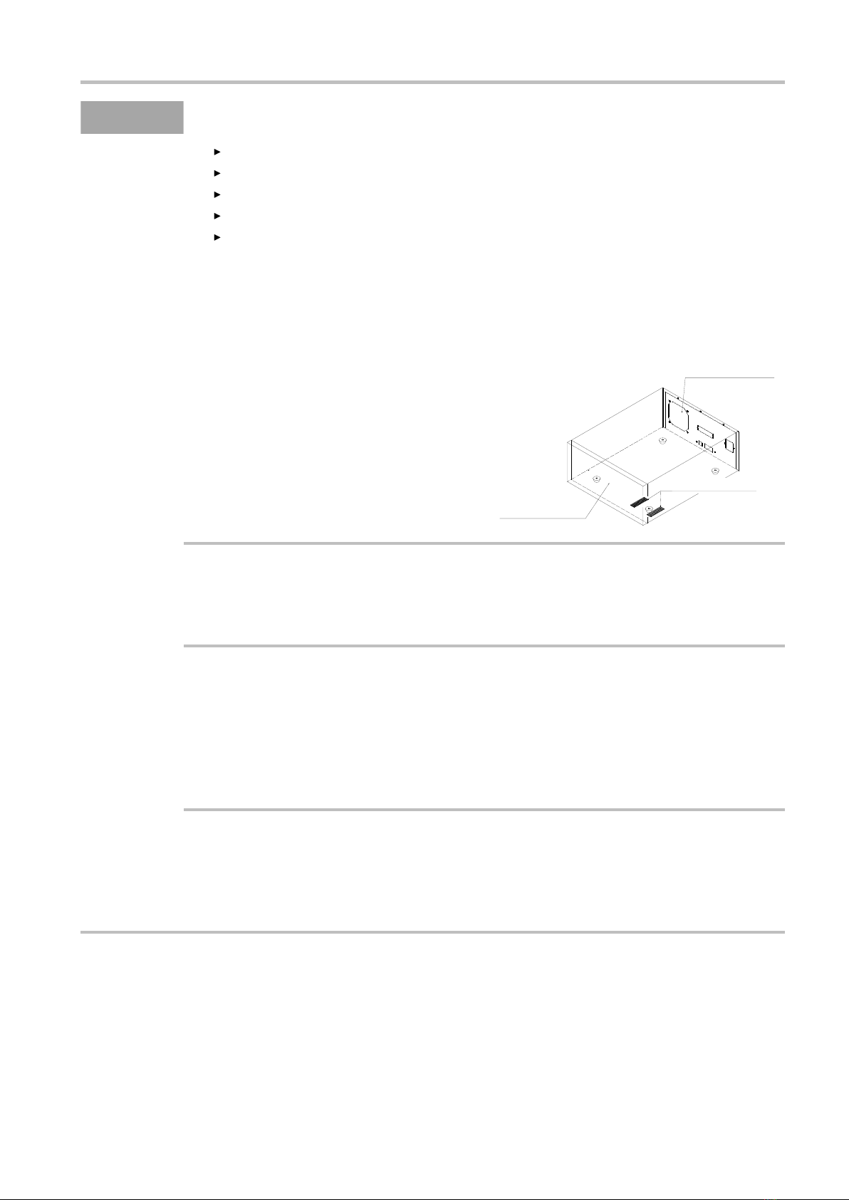
Cooling system of this tester is forced air cooling from
the rear panel. Mainly it takes in the air from the bottom
and discharge to the rear side. As heat may be trapped
and become the reason for the fire, always keep space of
more than 10cms between the top, side, rear and the
walls. In between the bottom surface and the floor (the
height of rubber foot is about 14mm), do not place any
object like paper, plastic etc. which can be easily sucked
in.
●Apply the voltage to capacitance load (test sample)
The output voltage may rise higher than the case of no load depending upon the capacitance value of the load.
Also, in case of voltage dependent load (test sample), the waveform distortion may occur.
In case of test voltage 2kV, the influence of capacitance less than 2000pF can be ignored.
●Transportation
・Hold the chassis (bottom plate) during transportation.
Do not carry the tester holding its red bushing of high voltage terminal section (refer to ⑩ of “1. Part
names and functions”).
※The bushing (red) may get damaged and there is a risk of serious injury when this product falls down.
・Minimize the mechanical vibration or shock when transporting the tester.
※There is a risk of damage of internal mechanism or malfunction.
●Regarding Interlock
This tester is provided with interlock function.
No test can be made when interlock function is in operation.
The interlock function can be released by plugging the enclosed remote /out plug into the remote I/O
connector ⑤ and pressing the stop switch ⑫.
Front panel
Exhaust exit
Suction inlet

Content
Preface................................................................................................................................1
Functions ................................................................................................................................................ 1
Confirmation prior to use.................................................................................................2
Inspection at the time of unpacking ....................................................................................................... 2
Cautions for handling ............................................................................................................................. 2
1.Names and functions of each part ..............................................................................3
Front Panel ............................................................................................................................................. 4
Rear Panel .............................................................................................................................................. 7
2.Preparation before use.................................................................................................9
Connection of power cord .................................................................................................................... 10
Connection of the protective earth terminal ......................................................................................... 10
Method of removing and mounting of key cover (option) ................................................................... 10
Connection to the external control equipment ...................................................................................... 11
Connection of the high-voltage cable ................................................................................................... 11
Power on and off .................................................................................................................................. 12
3.Panel operation ..........................................................................................................13
Expression of the panel display of setting operation ............................................................................ 14
Key Lock ............................................................................................................................................. 14
Configuration of the display................................................................................................................. 15
Setting of test conditions ...................................................................................................................... 15
READY state ....................................................................................................................................... 16
Display during the test ......................................................................................................................... 17
Display example of judgment result ..................................................................................................... 17
4.Setting of a single test and an automatic test (ACW→IR, IR→ACW).................19
Types of test ......................................................................................................................................... 20
Selection of test mode .......................................................................................................................... 21
5.Setting of withstand voltage test conditions.............................................................23
Setting of test voltage ........................................................................................................................... 24
Upper limit judgment value ................................................................................................................. 25
Lower limit judgment value ................................................................................................................. 26
Setting of the voltage rise time (rise time) ........................................................................................... 27
Setting of the voltage fall time (fall time) ............................................................................................ 28
Setting of the test time ......................................................................................................................... 29
Setting of test voltage frequency .......................................................................................................... 30
6.Setting of insulation resistance test (IR) conditions................................................31
Setting of test voltage ........................................................................................................................... 32
Setting of resistance range ................................................................................................................... 33
Upper limit judgment and lower limit judgment value ........................................................................ 34
Setting of mask time ............................................................................................................................ 35
Setting of test time ............................................................................................................................... 36
7.Memory operation .....................................................................................................37
Overview .............................................................................................................................................. 38
Call and setting of memory .................................................................................................................. 39

8.Program operation.....................................................................................................41
Overview .............................................................................................................................................. 42
Flow of program operation................................................................................................................... 43
Call of program operation .................................................................................................................... 44
Setting of the program.......................................................................................................................... 45
9.Test method (From the start of the test till the judgment) .....................................47
Method operation of single withstand voltage test ............................................................................... 48
Operation method of single insulation resistance test .......................................................................... 49
Operation method of automatic test ..................................................................................................... 50
Operation method of program operation test ........................................................................................ 51
10.Other functions........................................................................................................53
Double action start ............................................................................................................................... 54
GOOD hold .......................................................................................................................................... 54
Momentary start ................................................................................................................................... 54
FAIL mode ........................................................................................................................................... 54
NG start ................................................................................................................................................ 54
Setting method ..................................................................................................................................... 55
Setting of the buzzer ............................................................................................................................ 56
Interlock ............................................................................................................................................... 57
11.Remote I/O..............................................................................................................59
Test contents depending on remote I/O ................................................................................................ 60
Connector pin array and pin function ................................................................................................... 61
Call Memory No. from remote I/O ...................................................................................................... 62
Combination of Memory No. and MEM SET Signals ......................................................................... 63
I/O control by MEM SET .................................................................................................................... 64
I/O control by REAR MODE ............................................................................................................. 65
I/O Control with combination of REAR MODE and MEM SET ......................................................... 67
I/O Control with separate judgment(During GOOD judgment) ...................................................... 68
I/O Control with separate judgment(During ACW-NG Upper limit judgment) .............................. 69
I/O Control with separate judgment(During IR-NG lower limt judgment) ..................................... 70
Timing Chart: Details from the start to the high voltage output ........................................................... 71
Interlock signal .................................................................................................................................... 72
Protective function operation (PROTECTION) .................................................................................. 72
Input signal .......................................................................................................................................... 73
Output signal and the control power supply ......................................................................................... 74
12.PC remote control....................................................................................................75
RS-232C・USB Interface ...................................................................................................................... 76
13.Error message..........................................................................................................77
Error display ........................................................................................................................................ 78
Coping with error display .................................................................................................................... 78
14.Maintenance.............................................................................................................79
Cleaning ............................................................................................................................................... 80
Problem solving ................................................................................................................................... 80
Calibration ........................................................................................................................................... 80

15.Specifications ...........................................................................................................81
Withstand voltage test .......................................................................................................................... 82
Insulation resistance test ...................................................................................................................... 84
Memory operation ................................................................................................................................ 85
Program operation ................................................................................................................................ 85
Other functions .................................................................................................................................... 86
Input Output signal .............................................................................................................................. 86
RS-232C・USB Interface ...................................................................................................................... 87
General specification............................................................................................................................ 88
Setting of the default value .................................................................................................................. 88
Dimensions .......................................................................................................................................... 90
MEMO ................................................................................................................................................. 91

MODEL 8505 1
Preface
For proper use of this tester, read these instructions carefully before initial operation. Make sure that
this instruction manual is available to the responsible person for the operation. Besides, keep this
manual near the tester so that the operator can read it any time.
Functions
As this tester handles the high voltage, so it is designed with a lot of protective functions and a number
of considerations for the safety of the users.
・The withstand voltage tester has the capability of maximum output of 5kV and output capacity of
100VA.
・Precise test can be made due to upper and lower limit leakage current setting.
・As the insulation tester, this model is provided with 6 ranges of DC25V~DC1000V.
・The displays of test voltage, current and test time are easy-to-read green large LED.
・16 sets of memory are equipped which can write and read the test conditions.
・16 sets of memory are equipped which can program 16 steps of applied voltage of withstand
voltage test and test time.
・It is possible to control input of the start/stop of the test from the outside by remote I/O connector.
Besides, matching with the status of this tester, the output signals like “waiting”, “under test” or
“decision result” etc. are output in open collector.

MODEL 8505 2
Confirmation prior to use
Inspection at the time of unpacking
(1)When unpacking
When the tester is delivered, check whether it has been damaged in transit and unpack it carefully.
In case the tester does not operate as per the specification due to damage, contact the dealer from
where you have purchased or sales office.
(2)Checking of the contents
Check the packing box which contains the main item and the standard accessories as listed below.
List of accessories
Instruction manual (Main document) 1 set
RS-232C・USB Interface manual 1 set
High voltage cable 2m 1 pair
Earth wire 3m 1 piece
Power supply cord 2.5m 1 piece
Remote I/O plug 1 piece(36P)
!Caution
・For external communication RS-232C(D sub 9 pin model 5881-11-020)
When the customer procures it, it is requested to use the inch pitch screw type.
USB cable (Standard A-B model 5881-12-010) is optional.
Cautions for handling
Since this tester deals with high voltage, it is designed paying special attention to the safety. However, it
is still dangerous as it outputs high voltage of max. 5kV. An erroneous handling may cause fatal
accident. In order to avoid any accident, strictly observe the following cautions and take utmost care for
safety.
!Warning
If the earthing is insufficient, there is a risk of electric shock.
(1)Make sure to connect the protective ground terminals (rear panel) to the earth. If the grounding
is insufficient and the output is short-circuited to the earth or power supply line, the tester
housing is charged with high voltage and it is very dangerous when the operator touches the
outer box.
Check if the earthing cable is disconnected or not.
(2)During the test, never touch the output terminals, high voltage cable and test samples.
(3)When making a connection to the test sample, with output OFF , connect the LOW side prior
to other.
(4)When operating this tester, put on rubber gloves for electric shock prevention.

MODEL 8505 3
1.Names and functions of each part
Front Panel............................................................................................................................................. 4
Rear Panel .............................................................................................................................................. 7

1.Names and functions of each part
MODEL 8505 4
Front Panel
No.
Name
Function description
1
DANGER Lamp
Gives warning lamp when the test voltage is an
output.
Lighting of each lamp, refer
blinking state
2
MEMORY No.
Memory operation, display of memory number and step number of program operation
Memory, Lit up during program operation , blinking during setting up
PROG Lamp
During program operation, Lit up during
setting
Lighting of each lamp, refer
blinking state
3
TEST VOLTAGE
Withstand voltage test : Display of setting of test voltage and value of output voltage.
Program operation : Setting of step off (end) (withstand voltage test only)
Insulation test : Setting of the test voltage
V, kV Lamp
Unit display of test voltage
Lighting of each lamp, refer
blinking state
4
FREQ Display
Display of the frequency setting of the test voltage in regards to withstand voltage test
5
CURRENT
/RESISTANCE
Withstand voltage test : Display of leakage current measurement value and result
value, blinking during setting up
Insulation test : Display of insulation resistance measurement value and result
value, blinking during setting up
HIGH SET Lamp
Lights up when upper limit value is set
Lighting of each lamp, refer
blinking state
LOW SET Lamp
Lights up when lower limit value is set
6
TIME
Withstand voltage test : Display of RAISE、TEST、FALL time
Insulation test : Display of MASK、TEST time
RAISE Lamp
During withstand voltage test RAISE operation,
Lights up during setting
Lighting of each lamp, refer
blinking state
TEST Lamp
During withstand voltage test TEST operation,
Lights up during setting
FALL Lamp
During withstand voltage test FALL operation,
Lights up during setting
MASK Lamp
During MASK time of insulation test, Lights up
during setting
1413129 10
87654321
11
mA
HIGH
LOW
GOOD GOOD
HIGH
L O W
HIGH
L O W
MΩ
15 16

MODEL 8505 5
1
No.
Name
Function description
7
JUDGE
Display of decision result and test status
ACW-TEST Lamp
Lights up during withstand voltage test
Lighting of each lamp,
refer blinking state
IR-TEST Lamp
Lights up during insulation test
GOOD Lamp
Lights up when the decision result of the test is passed
HIGH Lamp
Lights up when the decision result of the test is larger than the
upper limit decision value
LOW Lamp
Lights up when the decision result of the test is less than the
lower limit decision value
8
MODE
Display of test mode and operation mode
ACW-IR Lamp
Withstand voltage test → Lights up in insulation test mode,
blinking during setting
Lighting of each lamp,
refer blinking state
IR-ACW Lamp
Insulation test → Lights up in withstand voltage test mode,
blinking during setting
ACW Lamp
Lights up during withstand voltage test mode , blinking during
setting
IR Lamp
Lights up during insulation test mode, blinking during setting
READY Lamp
Lights up during READY status
REMOTE Lamp
Lights up during remote control status
KEYLOCK Lamp
Lights up during locked status of key operation setting
DISCHARGE Lamp
Blinking during the discharge of insulation test
1.Names and functions of each part
MODEL 8505 6
No.
Name
Function description
9
LOW terminal
Low-voltage side terminal of the test voltage output, the tester case and the same
potential
10
HIGH VOLTAGE terminal
High-voltage side terminal of the test voltage output, the output of the high voltage
during the test
11
Buzzer
Buzzer
12
START switch
Start switch of the test
13
STOP switch
Interruption and judgment return switch of the test
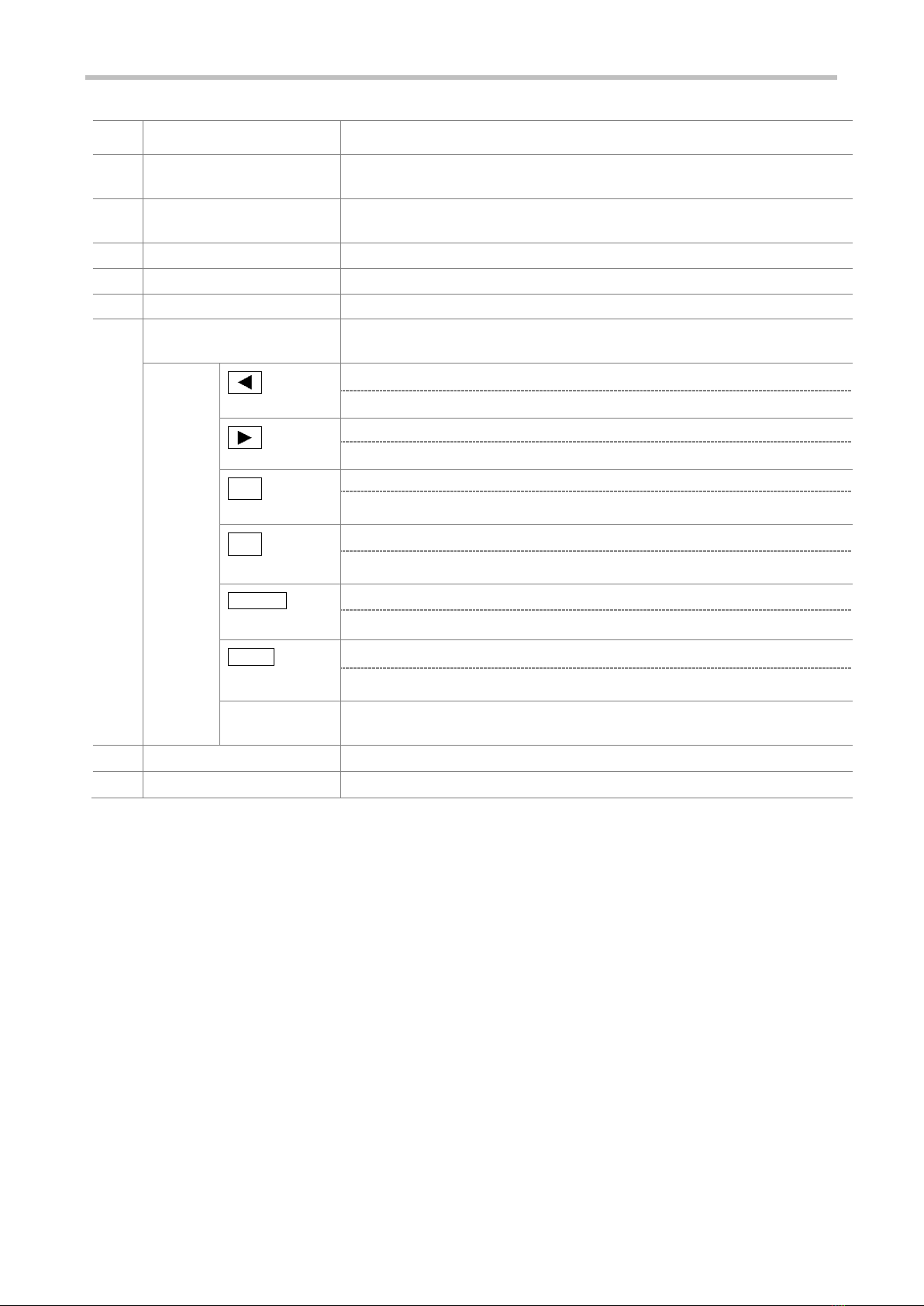
14
Setup key
Key for reading and writing the setting of the test conditions such as test mode, test
voltage, upper and lower limit values, test time etc.
MEM
Key to select each setting after entering the setup mode
Hold down the SHIFT and press the MEM key to switch to the memory operation
PROG
Key to select each setting after entering the setup mode
Hold down the SHIFT and press PROG key to switch to the program operation
▼
SET
Key to change each setting item
Hold down the SHIFT and press SET key for some time to switch to other function
setting
▲
RANGE
Key to change each setting item
Hold down the SHIFT and press RANGE key while setting to switch to the decimal
point
REMOTE
LOCK
Key to set/release remote operation
Hold down the SHIFT and press LOCK key to switch to Key lock set/release
ENTER
EXIT
Stores the set value and exits from the setting operation
Hold down the SHIFT and press EXIT key to interrupt the setting operation and
READY state
SHIFT
Used in combination with other keys
Function that is displayed on the lower side of the key is enabled
15
POWER switch
Switch for the power
16
Key cover
Protect the set up key from being touched (option)
MODEL 8505 7
1
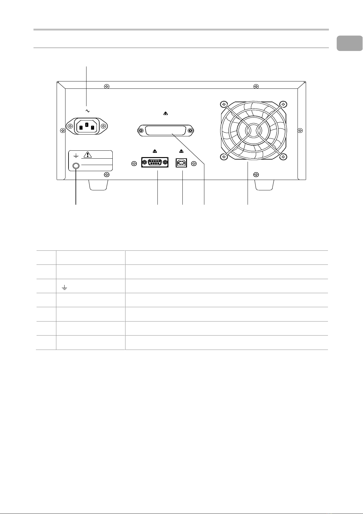
Rear Panel
No.
Name
Function description
1
AC LINE connector
Supply power inlet
2
Protective earth terminal. Terminal for earthing the case of the tester with same
potential
3
RS-232C connector
RS-232C interface
4
USB connector
USB interface
5
Remote I/O connector
Connector for external control
6
Cooling fan
Fan for exhaust
注 意
CAUTION
大 地 ア ー ス し て く だ さ い 。
接 地 端 子 は 確 実 に
ENSURE GROUNDING OF
EARTH TERMINAL.
1
2 3 4 5
REMOTE I/O
RS-232C USB
AC LINE 200VA MAX
100-240V 50-60Hz
6


MODEL 8505 9
2.Preparation before use
Connection of power cord.................................................................................................................... 10
Connection of the protective earth terminal ......................................................................................... 10
Method of removing and mounting of key cover (option) ................................................................... 10
Connection to the external control equipment ..................................................................................... 11
Connection of the high-voltage cable .................................................................................................. 11
Power on and off .................................................................................................................................. 12

2.Preparation before use
MODEL 8505 10
Connection of power cord
1Make sure that the power switch POWER of this tester is turned off.
2Connect the power cord to the inlet for the power supply of the rear face.
The plug of the power cord that comes with this tester is for AC100V. If it exceeds AC125V, use
the power cord suitable for the rating. 200V type power cord with a plug attached (European 2-pole
with earth model name 5880-23-030) is optional.
3Power cord plug (3P) is connected to the earthed outlet.
The plug of the power cord is 3- pin and the round shaped pin of the center is the earthing.
!Warning
Use supply voltage AC100~AC240V (AC90~250V) and power frequency 50/60Hz. Besides,
when you connect the power cord, make sure that the power switch is turned off. Beyond this
range could lead to the failure and incomplete operation of the tester.
Connection of the protective earth terminal
Earth the protective earth terminal ② to the ground using the supplied earthing wire. When the
earthing is imperfect or when the output is short circuited to the ground or power line, the case of the
tester is highly charged and it is dangerous to touch it. Besides, when using the tester, be sure to check
that the earthing wire is not disconnected.
!Warning
If the earthing is imperfect, there is a risk of an electric shock.
Method of removing and mounting of key cover (option)
You can mount the key cover (Model 5858-19) to the set up key as an option.
It is used when the set value is not wanted to be processed. As it is fixed with knurled screws, removing
and mounting can be done easily with your fingers.
MODEL 8505 11
2
Connection to the external control equipment
External control equipment can be connected to the remote I/O connector ⑤
Refer to “11.Remote I/O” for connection method.
Connection of the high-voltage cable
During the test, the high voltage output terminal is charged to a high voltage. Connect the supplied high
voltage cable with the HIGH VOLTAGE terminal and LOW terminal. For high voltage cable, use the
supplied cable or cable adaptable for the voltage used.
!Warning
・Make sure to confirm the power off before connecting the high voltage cable. There is
a risk of an electrical shock.
・As the vinyl covering part of alligator clip of the supplied high voltage cable is not a
withstand voltage, do not touch during the test. There is a risk of an electric shock.
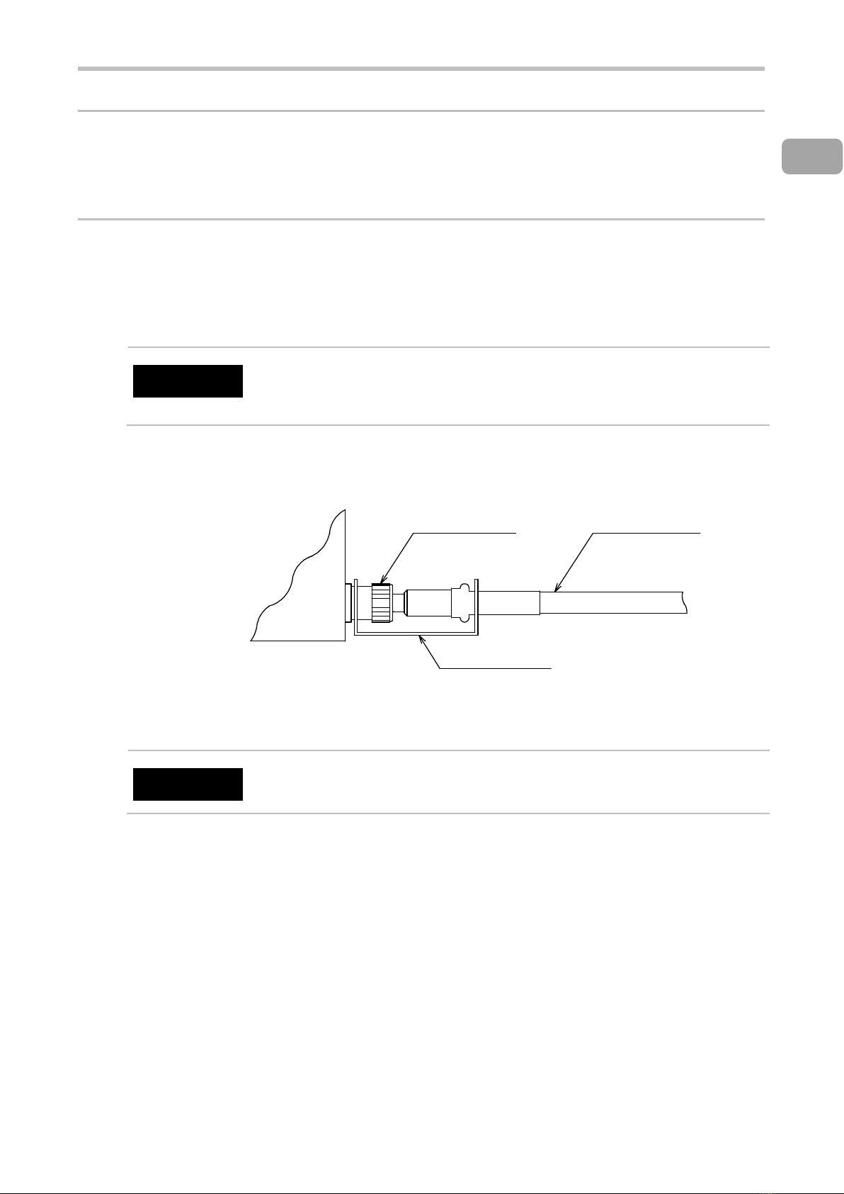
After connecting the low-voltage side cable to the LOW terminal ⑨, be sure to secure the retaining
bracket to the terminal.
Tighten the low terminal of the main body with the U shaped groove side of the retaining bracket
!Warning
When the low voltage side cable is disconnected, the whole tested equipment gets charged with
high voltage and there is a risk of an electric shock.
8505
MAIN
BODY
LOW TERMINAL ⑨LOW VOLTAGE CABLE
(BLACK)
Retaining bracket

2.Preparation before use
MODEL 8505 12
Power on and off
After purchasing for the first time when POWER switch⑮ is on, the test begins and due to interlock
function, the state becomes PROTECTION state. Connect the supplied remote I/O connector.
Use the supplied remote I/O connector only after the PROTECT state is released easily.
If you do the actual test, use the interlock function for the safety.
To guard the test area against the electric shock, use the interlock function like cut-off etc.
when opening the door or cover.
1Make sure that the power cord, connection cables etc. are connected properly.
2Press “-” side of POWER switch ⑮ of front panel to turn it on.
3After turning on the power switch, all lights on display are on for few seconds (lamp test).
However, TEST VOLTAGE and CURRENT/RESISTANCE display firm version.
After a few seconds, the display would be of test mode when the previous power was turned off.
4Press “○” side of the POWER switch of the front panel to turn it off.
!Caution
Do not turn off the POWER switch ⑮ during the test voltage output. This may cause a malfunction.
However, it excludes in the state of emergency stop when voltage output does not decrease even
when the STOP switch is pressed due to the abnormality of test sample etc.

MODEL 8505 13
3.Panel operation
Expression of the panel display of setting operation ............................................................................ 14
Key Lock ............................................................................................................................................. 14
Configuration of the display ................................................................................................................ 15
Setting of test conditions ..................................................................................................................... 15
READY state ....................................................................................................................................... 16
Display during the test ......................................................................................................................... 17
Display example of judgment result .................................................................................................... 17

3.Panel operation
MODEL 8505 14
Expression of the panel display of setting operation
Depending on the key operation, the state of the display unit LED is expressed as below:
Numerical Indicator
Surface-emitting
LED Lamp
Round LED
Lamp
On state
Blinking state
Off state
!Caution
During setting, if key is not operated for about five minutes, it automatically returns to READY state.
During this time the contents changed will not be stored.
Key Lock
With this operation, the setting key operation is disabled.
At this time, only START switch and STOP switch are enabled in front panel operation.
Setting of Key Lock ① Press LOCK key (pressing the LOCK while holding down the SHIFT) for 3 seconds in the READY
state.
② KEY LOCK lamp is lit and the key lock function is set.
Release of Key Lock ③ Press LOCK key (pressing the LOCK while holding down the SHIFT) for 3 seconds till KEY
LOCK lamp is off.
ACW-IR
ACW-IR
ACW-IR
mA
1
3
HIGH
Table of contents
Other Tsuruga Test Equipment manuals


