Tsuruga 8526 User manual

TSURUGA ELECTRIC CORPORATION
I-01990-1
MODEL 8526
AC/DC Withstanding Voltage Tester
Instruction Manual

FOR SAFE USE
For safe use of this product, please observe the following warning and caution. In order to help the users’
safe use of the products, the following symbol marks are used in this manual.
This is the warning to avoid the danger when it is assumed that such danger as
may cause fatal accident or severe injure to a user occurs in case that the product
is mishandled.
This is the caution to avoid the danger when it is assumed that such danger as may
cause minor injure to a user or generate only physical obstacle occurs in case that
the product is mishandled.
WARNING
This tester outputs high voltage. As there is danger of an electric shock, please strictly
follow the directions below:
●Do not touch high voltage cables or test samples during the test.
The places marked with on the tester are the dangerous parts where the
high voltage is generated.
●Make sure to connect the protective ground terminal to the earth.
●Do not short-circuit the output to the ground or commercial power supply line.
It is dangerous as the housing of tester is charged with high voltage. It also causes
the break-down of the tester.
●When operating the tester, put on the rubber gloves for an electric operation.
●For the connection to the sample to be tested, use the attached high voltage
cable or an electric cable appropriate to the operating voltage.
●Do not repeat ON/OFF of the power supply switch. It is dangerous and causes the
break-down of the tester.
●Place for installation
Never install or use this product in the place where such explosive or flammable
materials as mentioned below are used or stored (Occupational Safety and Health
Laws, Enforcement RegulationsAppendix Table 1 Dangerous Materials.
[Explosive material], [Flammable material], [Inflammable material], [Flammable
gas], [Oxidizing material]
※Model 8526 internally uses the metallic materials. There is a fear of deterioration
due to corrosion or rust and explosion or inflaming by an electric spark.
●Do not put anything on the 8526 or use it as foot stool.
※It affects the heat radiation, causing internal heat up and breakdown.
※It may also cause a deformation of the top part of the product.
●When the voltage is applied to the capacitance load (test sample), the output
voltage may rise higher than the case of no load depending upon the capacitance
value of the load. Also, in case of the voltage liable load (test sample), wave
distortion may occur.
In case of test voltage 2kV, the influence of capacitance 2000pF or less can be
ignored.
CAUTION
Pay attention to the following cautions about the power supply.
This tester is equipped with a high voltage transformer 500VA, so it can happen in the
following cases that the considerably big current (a few 10A) flows to the commercial
power supply line which this tester is connected to.
During a few 10ms immediately after the start of withstanding voltage test.
During a few 10ms while this tester makes a NG (no good) judgement for the test
sample.
Take care for the capacity of supply power line and the other equipment or devices
connected to the same line.
Besides, in case that the stabilized AC power supply is used, depending upon the action
of its current limiter circuit, the output is turned ON/OFFat high speed. It eventually
generates the considerably big surge voltage and is very dangerous.
WARNING
CAUTION
CAUTION
●To avoid break-down, malfunction or other troubles, do not use the tester in such
places where:
exposed to rain, water drops or direct sunlight.
high temperature or humidity, heavy dust or corrosive gas.
affected by external noise, radio waves or static electricity.
unstable or of much mechanical vibration
high sensitivity measuring instruments or receiver locates nearby
●Do not open the case or modify the tester as it may cause a danger of an electric
shock or other troubles.
●In case that abnormal operation occurs, turn off the power supply switch
immediately and pull out the power supply cable from the plug socket.
●When doing the maintenance or checking, be sure to stop the use of product and turn
off the power supply.
●Do not use the product in the place of vibration or where the shock may occur as it
will cause the breakdown of the product.
MAINTENANCE & TRANSPORTATION
WARNING
●Take care that the water drops like rain do not wet the product.
*It may cause the electric shock or malfunction.
●Do not lay along the product. Also take care that the product does not fall down by
vibration or else.
*It may cause the damage of internal mechanism or malfunction.
CAUTION
●When the product is transported, hold the chassis (bottom plate).
Do not carry the product holding its red bushing at high voltage output terminal
section (refer to ⑥and ⑲of the article 3 Name of parts and functions).
*The bushing (red) may break, causing serious injury by the fallen 8526.
●Minimize the mechanical shock or vibration when transporting the product.
*It may cause the damage of internal mechanism or malfunction.
INTERLOCK
Model 8526is provided with interlock function.
During the interlock function is in operation, no test is allowed.
The interlock function can be canceled by connecting the attached REMOTE/OUT plug into the
REMOTE/OUT connector ⑱on the back and then pressing the STOP switch ②.
Please refer to the article 14.3 (P32) for the interlock function.

i
Contents
Page
1. Preface ································································································· 1
1.1 ●Initial setting at the time of delivery······················································· 1
2. Confirmation prior to use············································································ 2
2.1 ●Unpacking ···················································································· 2
2.2 ●Cautions for handling········································································ 2
3. Name of parts and functions ········································································ 3
3.1 ●Front panel···················································································· 3
3.2 ●Rear panel····················································································· 6
4. Preparation prior to use ·············································································· 8
4.1 ●Zero adjustment of output voltmeter······················································· 8
4.2 ●Connection of protective ground terminal ················································ 8
4.3 ●Connection with external control device·················································· 8
4.4 ●Connection of high voltage cable ·························································· 8
4.5 ●Connection of power supply cable························································· 9
4.6 ●Throw in and shut off of power source···················································· 9
4.7 ●Before the test ················································································ 9
5. Setting items in each mode·········································································10
5.1 ●READY status···············································································10
5.2 ●Setting mode of test condition·····························································10
5.3 ●Memory write-in mode·····································································10
5.4 ●Memory read-out mode ····································································10
6. Kind of test mode and flow of setting·····························································11
6.1 ●Kind of test mode ···········································································11
6.2 ●Flow of setting ··············································································11
7. Setting of test mode ·················································································12
7.1 ●Status of display and expression in instruction manual ································12
7.2 ●Selection of each test mode································································12
8. Setting of test condition for withstanding voltage test ··········································13
8.1 ●Test range of withstanding voltage test···················································13
8.2 ●Referential voltage··········································································14
8.3 ●High limit of leak current ··································································16
8.4 ●Low limit of leak current···································································17
8.5 ●Test time······················································································19
9. Memory function ····················································································21
9.1 ●Configuration of memory··································································21
9.2 ●Memory write-in············································································21
9.3 ●Memory read-out············································································22

ii
Page
10. Test procedure (from start to judgement result)···············································23
10.1 ●Setting of test voltage (before starting test)··············································23
10.2 ●Test operation················································································23
11. Key lock ···························································································26
12. Special test mode ·················································································27
13. Remote control····················································································28
13.1 ●Operation by REMOTE connector························································28
13.2 ●Operation by REMOTE terminal ·························································28
13.3 ●Operation by REMOTE/OUT connector·················································29
13.4 ●Operation by REAR:MEM ································································30
13.5 ●Priority of each remote control····························································30
14. External control···················································································31
14.1 ●Control by REMOTE/OUT connector····················································31
14.2 ●Arrangement and function of connector pins············································31
14.3 ●Interlock signal··············································································32
14.4 ●Protective function (PROTECTION)·····················································32
14.5 ●Output signals and power supply for control ············································33
15. Status output·······················································································34
15.1 ●Name of STATUS OUTPUT and condition for output·································34
15.2 ●Specifications of status output·····························································34
15.3 ●Setting of condition for status output·····················································35
16. Timing chart·······················································································36
17. Adjustment of buzzer sound·····································································37
18. Error message ·····················································································38
19. Maintenance·······················································································39
19.1 ●Cleaning······················································································39
19.2 ●Failure symptom ············································································39
19.3 ●Replacement of fuse ········································································39
20. Specifications ·····················································································40
1
1. Preface
For proper use of this tester, please carefully read these instructions before initial operation.
Please make sure that this instruction manual reaches the responsible person of operation
and also keep it near the tester so the operator can read it any time.
Model 8526 deals high voltage, so it is designed to provide many protective functions and
various concerns to secure the operators’ safety.
●As the AC withstanding voltage tester, this model has the capability of max. output 5kV
and output capacity 500VA, which allow for a withstanding voltage test of various
electronic equipment or components, in accordance with the various standard.
●As a DC withstanding voltage tester, this model has the capability of maximum output
5kV and output capacity 50W, which enables a safe DC withstanding voltage test,
leaving no residual electric charge in the test sample thanks to its automatic discharging
function.
●Referential voltage setting, which prevents the test from being started unless the test
voltage comes into the range of either higher value of ±5% of set value or ±50V, high
and low leak current setting, timer function ensures highly accurate measurement.
●Large green LED of high visibility is employed for the display of test voltage, current
and test time.
●9 memory is provided to write in and read out the test conditions regulated by the
various standards or regulations.
●Relay contact can be output as the status output during the test.
●By means of REMOTE/OUT connector, an output signal to show “waiting”, “in-test”
or “judgement”can be output in open collector, depending upon the status of the tester.
●This tester is also provided with the remote control connector and terminal blocks which
allows remote start/stop of the test. With use of this function jointly with judgement
result and output signals, it facilitates the automation and labour-saving.
1.1 ●Initial setting at the time of delivery
The tester has the following initial setting at the time of delivery from factory.
Function
Setting
Remarks
Key lock
OFF
For detail, please refer to the article 11.Key lock.
Double action
OFF
For detail, please refer to the article 12.
Special test mode.
GOOD hold
OFF
Momentary
OFF
FAIL mode
OFF
Memory (Common for No.1~No.9)
At the delivery from factory, the following data is written in every memory No.1~9.
Keep pressing ENTER key and SHIFT key together, power on the tester, then the
settings are reset to the initial ones at the time of delivery.
Test mode
AC Withstanding voltage test
condition
DC Withstanding voltage test
condition
AC
Withstanding
voltage test
Test voltage range 2.5kV
Test voltage range 2.5kV
Referential voltage 0.00kV (OFF)
Referential voltage 0.00kV (OFF)
High limit leak current 10.0mA
High limit leak current 1.0mA
Low limit leak current 0.0mA (OFF)
Low limit leak current 0.0mA (OFF)
Test time 60.0s
Test time 60.0s
2
2. Confirmation prior to use
2.1 ●Unpacking
(1) Unpacking
When the tester is delivered, please check whether it has not been damaged in transit
and unpack it carefully. If any damage or inconvenience is found, please consult the
dealer whom you purchased the tester from for proper solution.
(2) Check of contents
Please do not leave in the carton any item of the contents listed below.
List of accessories:
High voltage cable 2m 1 pair
Earth wire 3m 1 piece
Power supply cord 2.5m 1 piece
REMOTE/OUT plug 1 piece (36P)
Fuse 7A 1 piece
Instruction manual 1 copy
RS-232C interface instruction manual 1 copy
RS-232C connector (D-sub 9 pins) Model 5881-11-020 (9 pins –9 pins / 2.0m) for
external communication is available at option. When a customer procures it,
please use the inch pitch screw type.
2.2 ●Cautions for handling
Since the Model 8526 deals high voltage, it is designed paying special attention to safety.
However, it is still dangerous as it outputs high voltage of max. 5kV. An erroneous
handling may cause fatal accident. In order avoid any accident, please strictly observe
the following cautions and take utmost care for safety.
(1) Make sure to connect the protective grounding terminals (back panel) to the earth. If
the grounding is insufficient, the tester housing is charged with high voltage when the
output is short-circuited to the earth or the power source line, and is very dangerous.
Please also check if the grounding cable is disconnected or not.
WARNING
Insufficient grounding may cause the electric shock.
(2) Never touch the output terminals, high voltage cable and test samples during the test.
(3) When making a connection to the test sample, connect the LOW side prior to the other,
with the output OFF.
(4) When operating the Model 8526, put a rubber glove for prevention of electric shock.
CAUTION
3
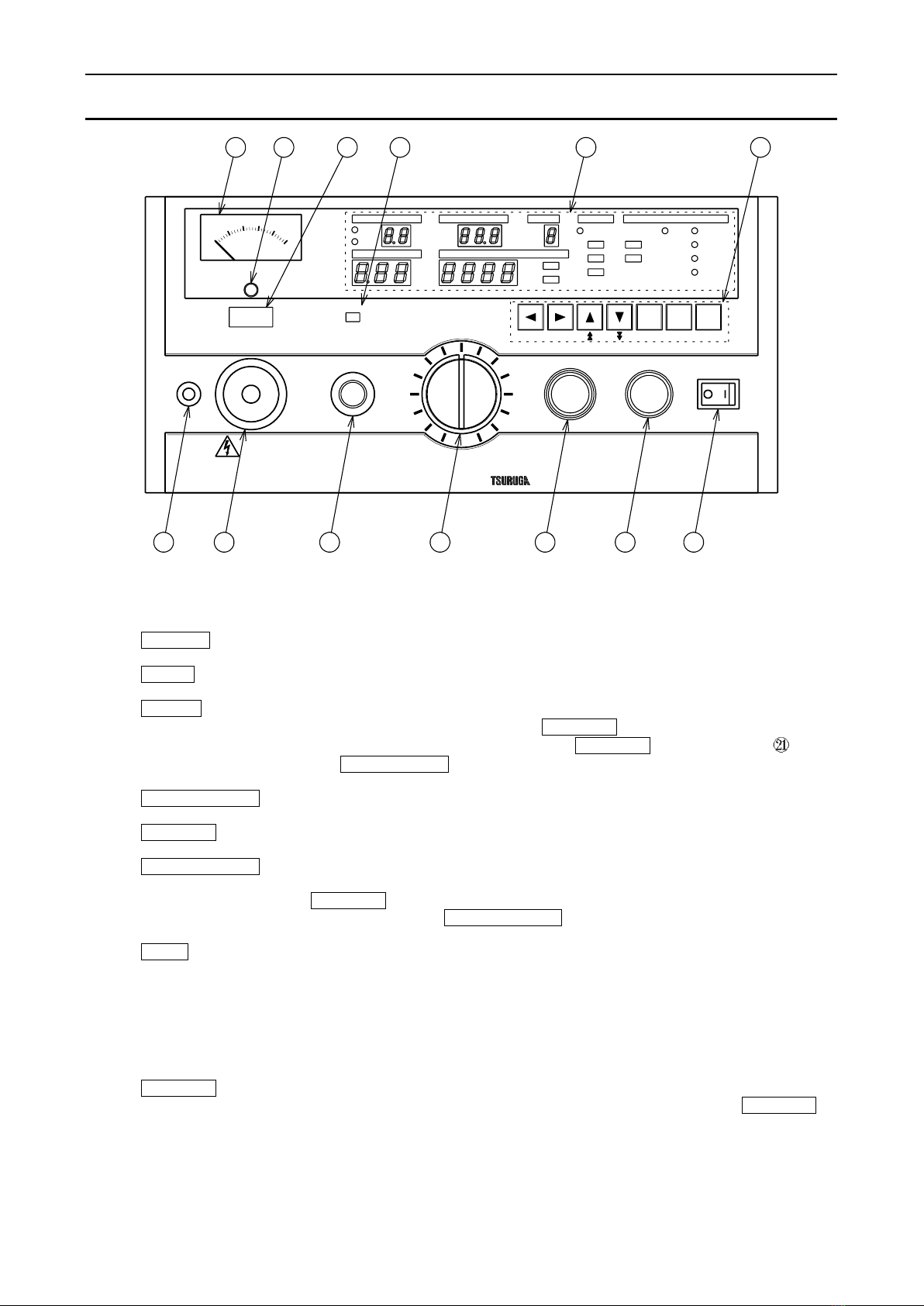
3. Name of parts and functions
3.1 ●Front panel
①POWER Power supply switch. Press right to turn ON and left to turn OFF.
②STOP Switch to interrupt the test operation and to reset a judgement.
③START Switch to start the test.
This switch is disabled when the REMOTE connector ⑤is used, or the
remote operation is made through the REMOTE terminal blocks or
the REMOTE/OUT connector ⑱.
④TEST VOLTAGE Knob to adjust the voltage of withstanding voltage test.
⑤REMOTE Connector for remote control.
⑥HIGH VOLTAGE High voltage side terminal of the test voltage output.
It outputs high voltage during the test, so never touch it during the
DANGER lamp ⑩is lit up. The operator may suffer electric shock.
It is common with HIGH VOLTAGE on the back panel.
⑦LOW Low voltage side terminal of the test voltage output. It is of the same
voltage as the case of this tester.
⑧Output voltmeter Electrical instrument to indicate the output voltage value.
⑨Zero adjuster Knob to adjust the zero position of the voltmeter for voltage tester.
The adjustment is done when no power is applied.
⑩DANGER lamp It gives warning during the test voltage is output.
Never touch the high voltage cable and test sample during the DANGER
lamp ⑩is lit up. The operator may suffer electric shock.
PROTECT
AC/DC WITHSTAND VOLTAGE TESTER MODEL 8526
REMOTE
MODEJUDGE
kV
AC
DC
DC
AC
ONLINE
DISCHARGE
KEY LOCK
READY
mA
CURRENTTEST VOLTAGE
BUZZER
LOCK
MAX
MAX 5kV
OUTPUT
HIGH VOLTAGE
REMOTE
TEST VOLTAGE
WRITE
READ
START STOP
EXIT
POWER
MIN
LOW
DANGER
TIME
RANGE MEMORY
s
No.
kV
kV
HIGH SET
LOW SET
GOOD
HIGH
LOW
SHIFTENTERON/OFF
8 9 10 11 12 13
7 6 5 4 3 2 1
4
Name of parts and functions
⑪Buzzer hole Aperture for the buzzer.
WARNING
Do not put any thing in the buzzer hole or insert a screwdriver or else.
●It may cause electric shock if touched with metal piece.
●It may also cause trouble of breakdown or mal-function.
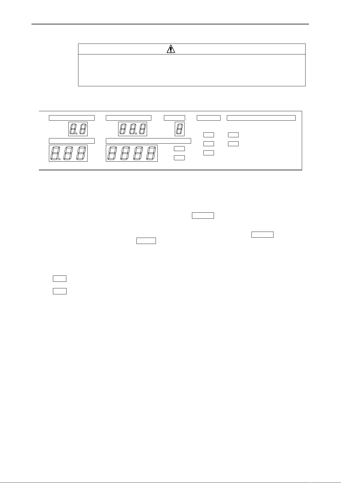
⑫Display section Displays the information of test condition, test result and so on.
READY lamp Lit up in READY status.
REMOTE lamp Lit up when the remote control is done.
During this lamp is lit up, the START switch ③is disabled.
KEY LOCK lamp Lit up when the key lock function is turned ON.
During this lamp is lit up, the switches other than the START switch ③
and the STOP switch ②are disabled.
DISCHARGE lamp Lit up during the discharging of DC withstanding voltage test.
ONLINE lamp Lit up while the tester is remote controlled via RS-232C.
AC lamp Lit up during the setting for the AC withstanding voltage test.
DC lamp Lit up during the setting for the DC withstanding voltage test.
Range display Displays the voltage range of AC/DC withstanding voltage test.
(RANGE) (2.5kV or 5.0kV)
Voltage display of During the setting of referential voltage, it displays the set value, and during
Withstanding volt test the test, it displays the output voltage value.
(TEST VOLTAGE)
Current/resistance During the setting of high and low leak current, it displays the set value
display (CURRENT) of leak current, and during the test, it displays the measured value.
PROTECT
○
ONLINE
○
○
○
○
○
KEY LOCK
DISCHARGE
REMOTE
READYAC
DC
○
○
No.s
mA
HIGH SET
SET
LOW
HIGH
GOOD
LOW
MODEJUDGE
CURRENTTEST VOLTAGE
MEMORY
RANGE TIME
kV
kV
AC
DC
5
Name of parts and functions
Test time display Displays the test time of each test (AC or DC withstanding voltage test).
(TIME) During the test it display the time remaining.
When the test time is set to OFF, the time lapse is displayed during the test.
HIGH SET Lit up at the setting of high limit leak current.
LOW SET Lit up at the setting of low limit leak current.
GOOD Lit up after the test, when the test judgement result is acceptable.
HIGH Lit up after the test, when the test judgement result is rejected for its high
limit.
LOW Lit up after the test, when the test judgement result is rejected for its low
limit.
Memory No. display Displays memory number being set in the memory mode.
(MEMORY No.)
PROTECT lamp Lit up when the PROTECTION is output.
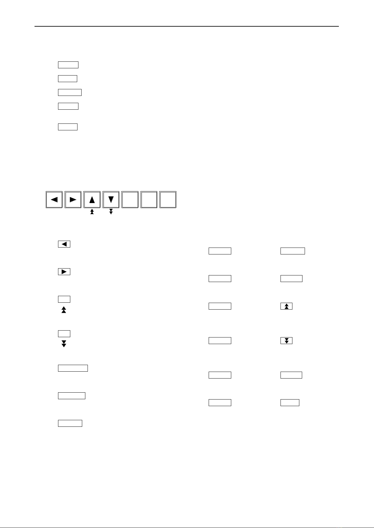
⑬Setting keys Keys to set the test condition such as referential voltage, leak current, test
time etc. and to write in or read out the memory.
key Key to feed and select each setting item toward left.
WRITE (When pressed together with SHIFT key, it becomes WRITE key used
for writing the memory.)
key Key to feed and select each setting item toward right.
READ (When pressed together with SHIFT key, it becomes READ key used
for read-out of the memory.)
▲key Key to increase the first digit of the set value one by one digit.
(When pressed together with SHIFT key, it becomes key used to
increase the second digit of the set value one by one digit.
When kept pressed, the digit continuously increases.
▼key Key to decrease the first digit of the set value one by one digit.
(When pressed together with SHIFT key, it becomes key used to
decrease the second digit of the set value one by one digit.
When kept pressed, the digit continuously decreases.
ON/OFF key Key for selection to set or not to set each setting item.
LOCK (When pressed together with SHIFT key, it becomes LOCK key and is
used to set/reset the key lock.)
ENTER key Key to finish the setting of test condition or to decide in memory setting.
EXIT (When pressed together with SHIFT key, it becomes EXIT key used to
interrupt the setting or memory mode and return to READY status.)
SHIFT key Shift key to use together with one of other keys.
(The function indicated on each key in blue letters becomes effective.)
ON/OFF ENTER SHIFT
WRITE READ LOCK EXIT
6
Name of parts and functions
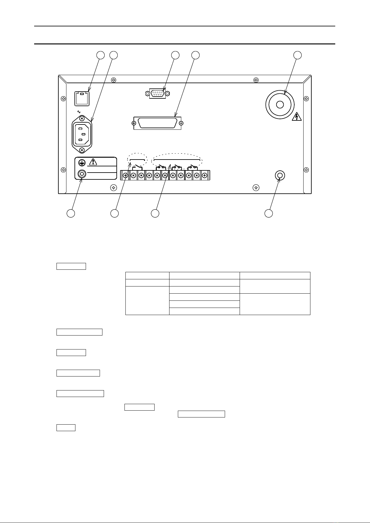
3.2 ●Rear panel
⑭Protecting grounding Terminal for grounding to the earth.
terminal Make sure to ground to the earth using the attached earth cable (green).
It is the same voltage as the case of the tester.
⑮FUSE 7A Fuse socket. The rate of fuse is as the following table shows.
Type
Power source voltage
Rate of fuse
Standard
100VAC
125V 7A
Optional
115V AC
200VAC
250V 4A
220VAC
240VAC
Do not use the fuse other than rated one.
⑯100V~50/60Hz Inlet for connection of supply power source.
It conforms to the attached power cord (3P).
⑰RS-232C Connector for RS-232C serial communication (D-sub 9 pins).
Refer to the instruction manual of interface.
⑱REMOTE/OUT Connector for the setting inputs of interlock and to output the output signals.
For detail, refer to the article 14.1 (P31).
⑲HIGH VOLTAGE High voltage side terminal of test voltage output.
It outputs high voltage during the test, so never touch it during the
DANGER lamp ⑩is lit up. The operator may suffer electric shock.
It is common with HIGH VOLTAGE on the front panel.
⑳LOW Low voltage side terminal of the test voltage output. It is of the same
voltage as the case of this tester.
100V 50/60Hz
FUSE 7A
CC CREAR:ONSTOPSTART
REMOTE
ac
NC
STATUS OUT
注 意
CAUT ION
PROTECT IVE EARTH TERMINAL .
ENSUREGROUNDINGOF
大地アース して ください 。
保護接地端子は確実に
RS-232C
REMOTE/OUT
LOW
HIGH VOLTAGE
OUTPUT MAX 5kV
1918171615
2014 2122

7
Name of parts and functions
REMOTE Terminal blocks for remote control.
START C When the REAR:ON C terminal is in short-circuit, the test is started by
short-circuiting the START C terminal.
When the REMOTE connector ⑤is in use, START C terminal is
disabled.
STOP C By making the short-circuit between the terminals, the test action can be
interrupted and the judgement result can be reset.
REAR:ON C By making the short-circuit between the terminals, the start of the test
becomes possible from the rear terminals. The START switch ③on
the front panel becomes ineffective.
For detail, refer to the article 13 (P28).
STATUS OUT Terminal blocks for status output.
For detail, refer to the article 15 (P34).
8
4. Preparation prior to use
4.1 ●Zero adjustment of output voltmeter
Before powering ON the power source switch, please confirm that the pointer of the
output voltmeter indicates “0”.
If it is deviated, make an adjustment turning the zero adjuster ⑨with the screwdriver.
4.2 ●Connection of protective ground terminal
Make sure to connect the protective grounding terminals (back panel) to the earth. If the
grounding is insufficient, the tester housing is charged with high voltage when the output
is short-circuited to the earth or the power source line, and is very dangerous.
Please also check if the grounding cable is disconnected or not.
WARNING
Insufficient grounding may cause the electric shock.
4.3 ●Connection with external control device
An external control device can be connected to the REMOTE connector ⑤,
REMOTE terminal , REMOTE/OUT connector ⑱and STATUS OUT
terminal .
For detail of connection, refer to the article 13~15 (P28~35).
4.4 ●Connection of high voltage cable
Choice of output section
Make a choice where to take out the high voltage output, either from the front panel or
from the rear panel. During the test, the high voltage output terminal at both front and
rear panel are charged with high voltage.
When the front panel is selected
Make a connection of the attached high voltage cable to the HIGH VOLTAGE terminal
⑥and LOW terminal ⑦.
When the rear panel is selected
Make a connection of the attached high voltage cable to the HIGH VOLTAGE terminal
⑲and LOW terminal ⑳.
Use the attached high voltage cable or the cable appropriates to the voltage to use.
WARNING
●Before making a connection of high voltage cable, ensure that the output
is OFF and the output voltmeter ⑧indicates “0”V.
There is a danger of electric shock.
●Avinyl coating of alligator clip of the attached high voltage cable has no
insulation withstandibility, so never touch it during the test.
There is a danger of electric shock.
●Take out the high voltage output at either side, front or rear panel.
Never use the both sides together, as it is very dangerous.
9
Preparation prior to use
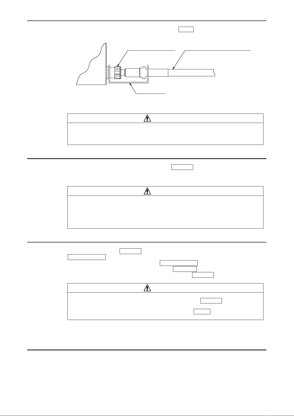
After connecting the low voltage side cable to the LOW terminal, make sure to fix
the locking metal to the terminal.
Fasten the U-shape ditch side to the LOW terminal of the tester main unit.
WARNING
If the low voltage side cable is disconnected, whole the test sample is charged
with high voltage and may cause a danger of an electric shock.
4.5 ●Connection of power supply cable
After confirming that the power supply switch POWER ①is OFF, connect the
attached power source cord to the inlet for the supply source power on the rear panel.
Connect the plug (3P) of power source cord to the socket with the earth connection.
WARNING
Confirm that the power source voltage is 100VAC, and use the tester within
the range of 90V~110VAC. Use of the tester out of this range causes a
breakdown or incomplete operation. In case of optional non-standard power
source voltage, use the tester within ±10% of the nominal voltage.
4.6 ●Throw in and shut off of power source
Before turning ON the POWER switch ①and throw in the power, confirm that the
TEST VOLTAGE knob ④is completely turned anti-clockwise to the end.
For shut off of the power supply, turn the TEST VOLTAGE knob ④clockwise
completely to the end, and after confirming the DANGER lamp ⑩is turned off
and the output voltmeter ⑧indicates 0V, turn OFF the POWER switch ①.
WARNING
While the test voltage is output, do not turn OFF the POWER switch ①,
as it will cause the breakdown, excepting such emergency case that the
voltage output can not decreased even though the STOP switch is pressed.
The test conditions at the time of power shutdown are retained even if the power is turned
OFF and the tester returns with these test conditions when the power is turned ON again.
4.7 ●Before the test
(1) Before powering on the tester, carefully read the article 2.2 Cautions for handling.
(2) For after the power source switch is turned ON, whole the display segments are lit up
(lamp test), and after the while lighting is finished, the tester enters into the test mode
the last time when the power is turned OFF.
Locking metal
LOW voltage side cable(black)LOW terminal ⑦or ⑳
Main
8526
10
5. Setting items in each mode
5.1 ●READY status
When the POWER switch ①is turned ON, the lamp test is done and then READY is
lit up showing that the tester enters in READY status.
The test condition at the previous power shutdown is displayed.
Pressing the START switch ③starts the test.
In READY mode, the setting of the following items can be done.
Items to set
(1) Test condition Refer to the article 7~8 (P12~20)
(2) Key lock Refer to the article 11 (P26)
(3) Buzzer sounding Refer to the article 17 (P37)
(4) Status output condition Refer to the article 15.3 (P35)
(5) Special test mode Refer to the article 12 (P27)
①Double action
②GOOD hold
③Momentary
④FAIL mode
5.2 ●Setting mode of test condition
In READY status, by pressing the (or ) key, READY is turned off and the
tester enters into the test condition setting mode.
In the test condition setting mode, the test mode and condition can be set or changed.
A press of ENTER key finishes the setting and the tester becomes READY status.
Item to set
Test mode Test condition
Ref. art. 7.2 (P12) Ref. art. 8 (P13~20)
5.3 ●Memory write-in mode
After setting the test condition in the test condition setting mode, press the WRITE key
(SHIFT + ), then the memory number blinks, being ready to write in the memory.
In the memory write-in mode, 9 memory sets can be written. Each memory set consists
of 6 items of test conditions which are set in the test condition setting mode.
A press of ENTER key finishes the setting and the tester becomes READY status.
Item to set
Test condition →Memory write-in (No.1) →Test condition →
Ref. art. 7.2 (P12) Ref. art. 9.2 (P21) Ref. art. 7.2 (P12)
Memory write-in (No.2) Test condition →Memory write-in (No.9)
Ref. art. 9.2 (P21) Ref. art. 7.2 (P12) Ref. art. 9.2 (P21)
5.4 ●Memory read-out mode
In READY status, by pressing the READ key (SHIFT + ), a memory No. blinks
and the tester becomes ready to read out the memory. In the memory read out mode, one
of the 9 memories written in [ref. art. 9.2 (P21)] can be called up and read out.
A press of ENTER key finishes the setting and the tester becomes READY status.
Item to set
Memory read out (Select memory No.) Ref. art. 9.3 (P22)
11
6. Kind of test mode and flow of setting
6.1 ●Kind of test mode
AC Withstanding voltage test
DC Withstanding voltage test
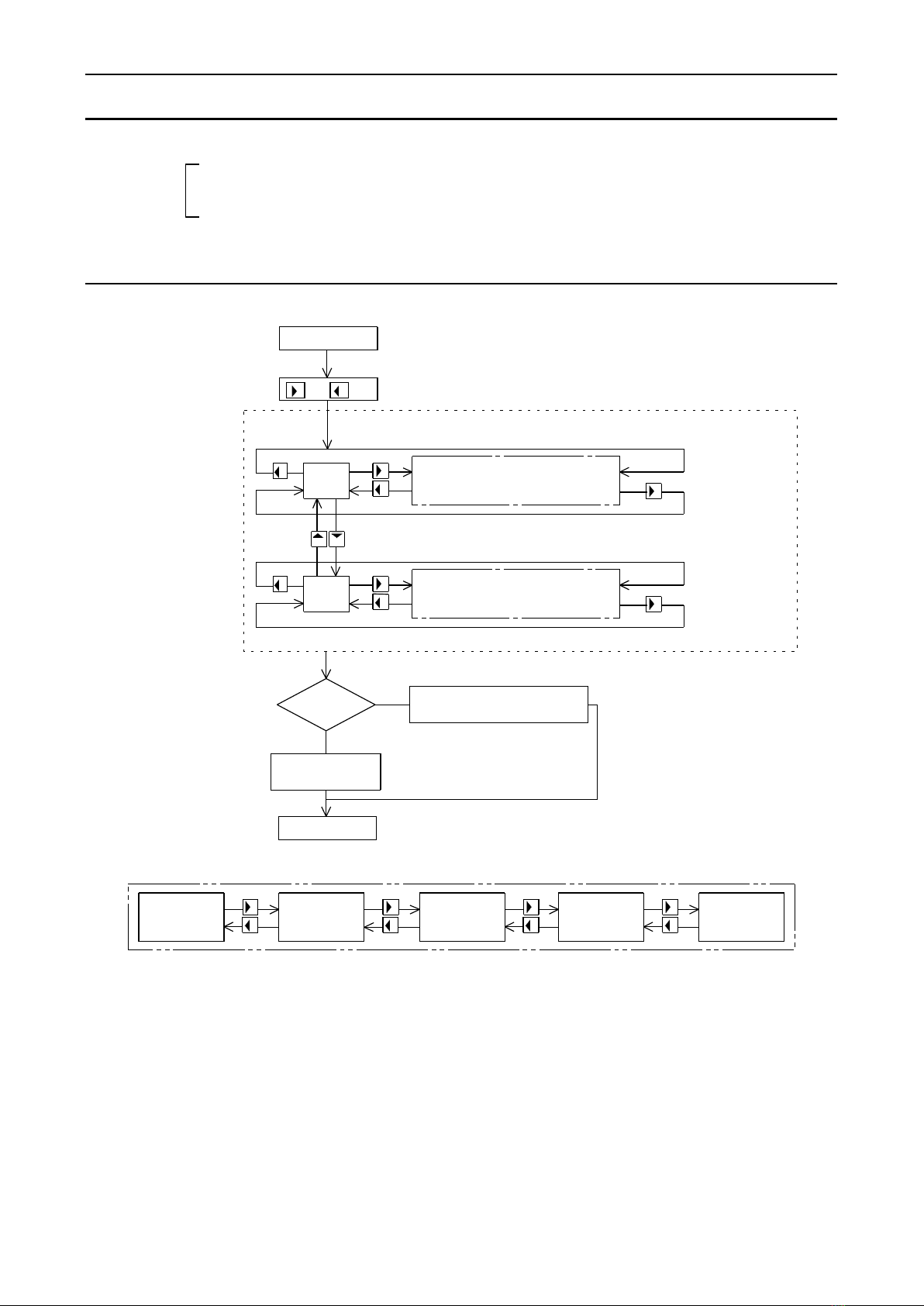
6.2 ●Flow of setting
READY status
After the setting, the mode previously set is initially lit up.
blinks
Setting of test condition of
or key
AC: AC Withstanding voltage test
AC blinks at delivery from factory.
AC
AC is lit up
blinks
Setting of test condition of
Memory of ENTER key
to memorize the set value
EXIT key
(SHIFT+ENTER)
YES
NO
setting
DC
DC is lit up
DC: DC Withstanding voltage test
READY status
AC Withstanding
voltage test
DC Withstanding
voltage test
Flow of setting for withstanding voltage test
Range Test time
Referential
voltage
leak current leak current
withstanding voltage test.
withstanding voltage test.
High limit of Low limit of

12
7. Setting of test mode
7.1 ●Status of display and expression in instruction manual
Digital display
Flat display
LED lamp
Lit-up mode
GOOD
●KEY LOCK
Blinking mode
GOOD
◎KEY LOCK
Turn-off mode
GOOD
○KEY LOCK
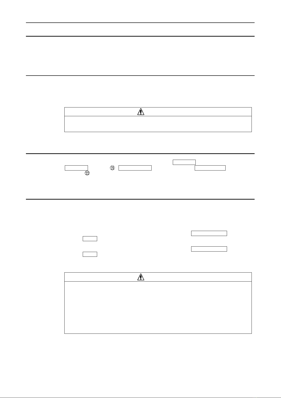
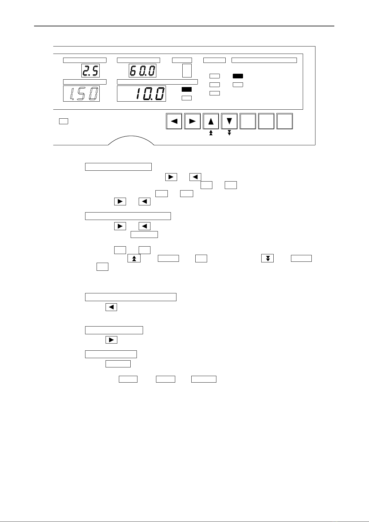
7.2 ●Selection of each test mode
The following 2 test modes can be set.
AC (AC Withstanding voltage test)
DC (DC Withstanding voltage test)
①To enter the setting for selection of test mode,
In READY status, press or key, then the test mode lamp blinks.
The test mode lamp moves up and down with ▲or ▼key. Set to the required
test mode lamp (blinking status). A press of ENTER key determines the selected
mode and the tester returns to READY status
②To enter the setting ofAC withstanding voltage test,
In the condition ①, while AC (AC withstanding voltage test) is in blinking, press
or key, then you can enter the setting of test condition for the AC
withstanding voltage test.
③To enter the setting of DC withstanding voltage test,
In the condition ①, while DC (DC withstanding voltage test) is in blinking, press
or key, then you can enter the setting of test condition for the DC
withstanding voltage test.
PROTECT
○
ONLINE
○
○
○
○
○
KEY LOCK
DISCHARGE
REMOTE
READYAC
DC
○
No.s
mA
SET
SET
LOW
GOOD
LOW
MODEJUDGE
CURRENTTEST VOLTAGE
MEMORY
RANGE TIME
kV
kV
●
AC
DCHIGH
HIGH

13
8. Setting of test condition for withstanding voltage test
The setting of test condition has to be made independently for theAC withstanding voltage
test and DC withstanding voltage test. The condition set in the AC withstanding voltage test
mode and in the DC withstanding voltage test mode is respectively valid for the AC, DC.
8.1 ●Test range of withstanding voltage test
Range to set: 2.5kV or 5kV
To enter setting mode
①In READY status, press or key, then the test mode lamp blinks. The test
mode lamp moves up and down with ▲or ▼key. Make the required test
mode lamp blinking ( AC or DC ).
②Press or key and make the test mode lamp lit up.
Setting of test voltage range
①Press or key and select the status that the AC or DC lamp is lit up, and the
test voltage range is blinking (refer to the above figure).
②Switch the test voltage to 2.5kV or 5kV with ▲or ▼key.
When the test voltage range is switched, the range display displays the selected
voltage value in blinking. A press of or key changes the display of
voltage value from blinking to lit up, then, move to the next item of condition setting.
To return to the previous setting
Press key, then the setting changes to that of test mode selection.
To the next setting
Press key, then the setting moves to the setting of referential voltage.
Finish of setting
Press ENTER key, then the tester returns to READY status, memorizing the settings
having been made.
When the EXIT key ( SHIFT and ENTER key at a time) is pressed in the setting
mode, the setting mode for the test condition is interrupted and the tester becomes
READY status.
The test conditions in this case are those before entering the setting mode of test
condition.
ON/OFF ENTER
WRITE READ LOCK EXIT
SHIFT
BUZZER
PROTECT
○
ONLINE
○
○
○
○
○
KEY LOCK
DISCHARGE
REMOTE
READYAC
DC
○
No.s
mA
SET
SET
LOW
HIGH
GOOD
LOW
MODEJUDGE
CURRENTTEST VOLTAGE
MEMORY
RANGE TIME
kV
kV
DC
AC
HIGH
●

14
Setting of test condition for withstanding voltage test
8.2 ●Referential voltage
Adjustable range: 0.00~5.00kV,OFF
[When turning OFF the setting of referential voltage]
To enter setting mode
①In READY status, press or key, then the test mode lamp blinks. The test
mode lamp moves up and down with ▲or ▼key. Make the required test
mode lamp blinking ( AC or DC ).
②Press or key and make the test mode lamp lit up.
To turn OFF the setting of referential voltage
①Press or key and select the status that the test voltage display blinks.
②Next, press ON/OFF key and select the status that the display blinks with
(refer to the above figure).
To return to the previous setting
Press key, then the setting changes to the setting of test range of withstanding
voltage test.
To the next setting
Press key, then the setting moves to the setting of high limit of leak current.
Finish of setting
Press ENTER key, then the tester returns to READY status, memorizing the settings
having been made.
When the EXIT key ( SHIFT and ENTER key at a time) is pressed in the setting
mode, the setting mode for the test condition is interrupted and the tester becomes
READY status.
The test conditions in this case are those before entering the setting mode of test
condition.
ON/OFF ENTER
WRITE READ LOCK EXIT
SHIFT
BUZZER
PROTECT
○
ONLINE
○
○
○
○
○
KEY LOCK
DISCHARGE
REMOTE
READYAC
DC
○
No.s
mA
SET
SET
LOW
HIGH
GOOD
LOW
MODEJUDGE
CURRENTTEST VOLTAGE
MEMORY
RANGE TIME
kV
kV
DC
AC
HIGH
●
15
Setting of test condition for withstanding voltage test
[When setting the referential voltage]
To enter setting mode
①In READY status, press or key, then the test mode lamp blinks. The test
mode lamp moves up and down with ▲or ▼key. Make the required test
mode lamp blinking ( AC or DC ).
②Press or key and make the test mode lamp lit up.
Setting of referential voltage
①Press or key and select the status that the test voltage display blinks.
②Next, press ON/OFF key and select the status that the display blinks with the
numeral.
③Press ▲or ▼key and set the referential voltage.
A press of key ( SHIFT and ▲keys at a time) or key ( SHIFT and
▼keys at a time) allows the setting of second digit (the digit of 0.10kV) (refer to
the above figure).
Note: The referential voltage can be set within the range of 0.00~5.00kV.
To return to the previous setting
Press key, then the setting changes to the setting of test range of withstanding
voltage test.
To the next setting
Press key, then the setting moves to the setting of high limit of leak current.
Finish of setting
Press ENTER key, then the tester returns to READY status, memorizing the settings
having been made.
When the EXIT key ( SHIFT and ENTER key at a time) is pressed in the setting
mode, the setting mode for the test condition is interrupted and the tester becomes
READY status.
The test conditions in this case are those before entering the setting mode of test
condition.
ON/OFF ENTER
WRITE READ LOCK EXIT
SHIFT
BUZZER
PROTECT
○
ONLINE
○
○
○
○
○
KEY LOCK
DISCHARGE
REMOTE
READYAC
DC
○
No.s
mA
SET
SET
LOW
HIGH
GOOD
LOW
MODEJUDGE
CURRENTTEST VOLTAGE
MEMORY
RANGE TIME
kV
kV
DC
HIGH
●
AC
Table of contents
Other Tsuruga Test Equipment manuals


