CESVA CB011 User manual

CB011 / CB012
Acoustic calibrator
USER'S MANUAL
M_CB011CB012_v0003_20211022_EN


1
, founded in 1969 in Barcelona, has always engaged in the
manufacturing of sound equipment and instruments with in-house R&D&I and
patents.
We are members of national and international committees for the creation and
review of regulations and standards.
has a flexible and efficient distribution network in more than 40
countries all over the world.
We provide our customers with an after-sales service that guarantees that our
instruments have a long service life, in addition to any periodic verification and
calibration services.
Our website is where you can find all the information you need to know about our
products, request free quotes with no commitment to purchase, download
software, get in touch with us, or simply keep abreast of all the training activities
and exhibitions that we regularly take part in.
Taking care of and listening to our customers brings us closer to them and allows
us to provide them with a measuring solution that is totally adapted to their
needs.
EN

2 Contents
1. What is in this manual? 3
2. Material and documentation 4
3. General description of the device 5
1.1 Main characteristics of the CB011 and CB012 5
1.2 Description of CB011 and CB012 6
4. Operation 8
1.3 Verification method 8
1.3.1 Operating mode 8
1.3.2 Permanent on mode 10
1.4 Changing the batteries 11
1.5 Summary of indicators 11
5. Technical specifications 12
1.6 Frequency and sound pressure level 12
1.7 Distortion 12
1.8 Environmental conditions of operation 12
1.9 Reference conditions 12
1.10 Dimensions and weight 13
1.11 Power supply 13
1.12 Electrostatic and radio frequency criteria 13
1.13 Standards 14
1.14 Certificates 14
1.15 Notes 14
6. Reference to standard 15
1.16 Standard UNE-EN IEC 60942:2019 15
Contents

Chapter 1 What is in this manual? 3
This manual provides you with all the information you need to learn about your
new acoustic calibrator.
The information is divided into 6 chapters:
Chapter two and three describe the main features of the device and its physical
parts.
Chapter four specifies its operation.
Chapter five details the technical specifications of the instrument.
And finally, chapter six shows the references indicated by the standard.
What is in this manual?
1. What is in this manual?
1

4 Chapter 2 Material and documentation
The first step is to check the material and documentation when purchasing the
CB011/CB012 acoustic calibrator:
CB011/CB012 acoustic calibrator
2 AAA alkaline batteries.
Documentation included:
User's manual.
Warranty.
If any of these items are missing, please contact your official
distributor.
Material and documentation
2. Material and documentation
2

Chapter 3 General description of the device 5
Proper verification of the sound level instruments is essential before and after
each series of measurements. The CB011 and CB012 acoustic calibrators
provide maximum reliability when performing these verifications.
The CB011 has been specially designed to verify class 1 and class 2 dosimeters
and sound level meters, and the CB012 to verify class 2 dosimeters and sound
level meters. These calibrators comply with UNE-EN IEC 60942:2019 class 1
(CB011) and class 2 (CB012).
Both calibrators are portable and very easy to use, which makes them useful for
verifying sound measuring instruments both in the laboratory and at the point of
measurement. The CB011 and CB012 generate a sound pressure level of 94 dB
(re 20 µPa) at a frequency of 1 kHz.
In addition, thanks to their internal structure and operating mode, they avoid
having to apply corrections for environmental conditions.
1.1 Main characteristics of the CB011 and CB012
The following features of the CB011 and CB012 should be noted:
They can be used with any microphone capable of being verified in a closed
cavity and with a diameter of ½".
They are recommended for the C-130, C140, C-250, C240, P05,
and P008 microphones.
The operation of these calibrators is based on a feedback system. The CB011
and CB012 have an internal microphone to check that the signal generated
through the speaker is always correct. This avoids having to apply any type of
correction, since the level generated is independent of the environmental
conditions in which the device is located.
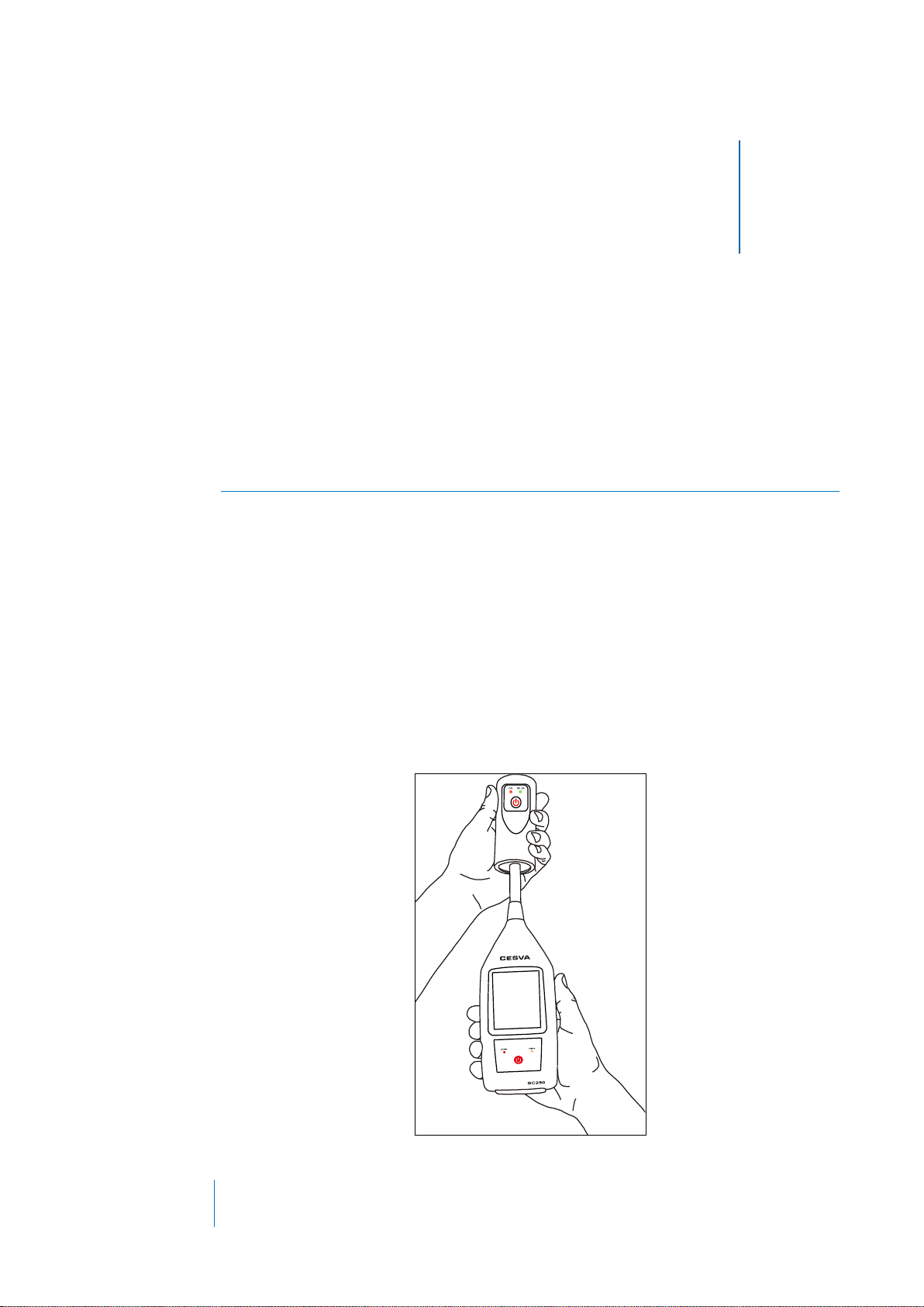
Both the CB011 and CB012 are operated with just one button. When pressed,
the calibrator generates a sound pressure level of 94 dB and uses 1 kHz as
the verification frequency, eliminating the need for corrections due to
frequency weightings, since these are zero at this frequency.
These calibrators also have a permanent on mode for long-term use.
The CB011 and CB012 calibrators have a protection system that prevents the
device from being turned on unintentionally, both after use and due to
accidental turned on.
General description of the device
3. General description of the device
3

6 Chapter 3 General description of the device
1.2 Description of CB011 and CB012
The following figure describes the most important parts of the CB011 and CB012:
1. Cavity · Cavity for inserting the microphone.
2. Power button · Button for turning the calibrator on and off.
3. Power Indicator ·When starting the calibrator, the red LED light should light
up. It also provides information on the status of the batteries (see 4.3)
4. Level indicator · Shows that the level 94 dB at 1 kHz emitted by the calibrator
is correct, lighting up in green (see 4.3).
5. Battery compartment · Compartment for the batteries.
6. Battery cover ·Remove it to change the batteries.
7. Fixing screw ·Screw to secure the battery cover.
8. IEC Marking ·In this area the model and serial number of the calibrator are
detailed, as well as the standards that it complies with.
9. CE Marking ·European conformity mark.
10. WEEE Marking ·Symbol that indicates the selective collection of electrical and
electronic devices.
11. Space for the national marking label ·Space reserved for the label
corresponding to the conformity marking (legal metrology).

Chapter 3 General description of the device 7

8 Chapter 4 Commissioning
To learn about the operation of the CB011 and CB012, it is advisable to read the
manual in its entirety.
1.3 Verification method
1.3.1 Operating mode
To start the verification of the measurement using the CB011 or CB012:
1) Insert the instrument into the calibrator, inserting the microphone part into the
verification cavity and enduring that it has reached the bottom of the cavity
and is parallel to the axis of the calibrator (see image). There may be a
certain amount of resistance, since the calibrator fits onto the microphone
tightly. Insert the instrument gently to avoid damaging the microphone.
Operation
4. Operation
4

Chapter 4 Commissioning 9
2) Turn on the instrument to be verified. And wait until the instrument is ready to
start measuring (see the instrument's Manual).
3) Start the calibrator using the power button (2). The power indicator (3) will
light up, indicating that the calibrator is on and that the status of the batteries
is correct (see 4.3).
4) Wait for the level indicator (4) to light up continuously (typically 3 seconds)
ensuring a stable and correct sound pressure level.
If the sound pressure level is not correct, the level indicator (4) will light up
intermittently (see 4.3) and after 20 seconds the calibrator will turn off
automatically.
5) Start a measurement with the instrument and obtain the value measured by
the instrument.
6) Compare this value with the effective verification level (Generated level +
correction factor).
The following table lists the correction factors for different microphones and
for two microphones commonly used in laboratory tests.
Brand
Model
Correction
factor
Effective level of
verification
dB
dB
CESVA
C-250
-0.1
93.9
CESVA
C-130
-0.1
93.9
CESVA
C240
-0.1
93.9
CESVA
C140
-0.1
93.9
CESVA
P05
-0.1
93.9
CESVA
P007
-0.1
93.9
B&K
4134
0.0
94.0
B&K
4180
0.0
94.0
NOTE:
The effective verification level is obtained by correcting the level
generated by the calibrator (94 dB) with the pressure to free-field
correction factor of the microphone at the frequency of 1 kHz. In the event
that the instrument to be verified is designed to measure in free field, this
factor must be applied. For instruments designed to measure in the
pressure field, no correction is necessary. This factor is equal to changing
the sign of the pressure to free field correction at 1 kHz, indicated in the
instrument's instruction manual.

10 Chapter 4 Commissioning
7) If the difference between the measured value and the effective verification
level is within the ranges recommended in the instrument's instruction
manual, the verification result is favourable. Otherwise, contact the nearest
official service.
8) At the end of the verification, stop the calibrator by pressing the power button
(2).
1.3.2 Permanent on mode
For certain applications it may be necessary to have the calibrator turned on
continuously for a long period of time. To do so:
1) Turn on the calibrator by pressing and holding the power button (for more
than three seconds) until the indicator (3) lights up intermittently (see 4.3)
indicating that the calibrator is working in permanent on mode and the status
of the batteries is correct (see 4.3). Then release the power button.
The level indicator (4) lights up continuously, thus ensuring a stable and
correct sound pressure level. If the sound pressure level is not correct, the
level indicator (4) will light up intermittently (see 4.3)
2) The verification is carried out in the same way as in section 4.1.1. Except to
finish the verification, you will need to turn off the calibrator by pressing the
power button (2).
NOTE:
The calibrator will automatically turn off 1 minute after being turned on.
This protection prevents the calibrator from being left on, to preserve the
batteries.
NOTE:
When the battery level is low, the calibrator behaves in the same way as in
section 4.1.1

Chapter 4 Commissioning 11
1.4 Changing the batteries
The CB011 and CB012 calibrators use two 1.5V AAA alkaline batteries. To
change the batteries, follow the steps below:
1) Using a screwdriver, unscrew the fixing screw (7).
2) Slide the battery cover (6) out.
3) Remove the batteries and insert the new batteries respecting the polarity.
4) Then replace the battery cover (6) and screw in the fixing screw (7).
5) Start the calibrator and verify that the power indicator (3) lights up
continuously.
1.5 Summary of indicators
INDICATOR
LED ILLUMINATION
DESCRIPTION
OF START UP [3]
CONTINUOUS
100% of the time on
Calibrator on
INTERMITTENT
90% of the time on
Calibrator on in continuous run mode
INTERMITTENT
50% of the time on
Low voltage batteries
OF LEVEL [4]
CONTINUOUS
100% of the time on
Correct sound pressure level
INTERMITTENT
50% of the time on
Incorrect sound pressure level
NOTE:
The batteries must be 1.5V alkaline type AAA, also known as LR03 (IEC)
and 24A (ANSI/ANDE). If the voltage is low, the power indicator (3) will
light up intermittently (see 4.3).
A flat battery may turn the calibrator on, but the voltage will soon drop and
the calibrator will turn off or indicate that the batteries are flat.
When the battery level is low, the calibrator behaves in the same way as in
section 4.1.1

12 Chapter 5 Technical Specifications
This chapter contains the technical specifications for the CB011 and CB012
calibrators:
1.6 Frequency and sound pressure level
Main frequency:
1 kHz
Main sound pressure level (re 20µPa):
94.0 dB
1.7 Distortion
Distortion:
Less than 2.5 %
1.8 Environmental conditions of operation
Relative humidity:
25 to 90 %
Static pressure:
65 to 108 kPa
Temperature:
Class 1 -10 to +50 ºC
Class 2 0 to +40 ºC
1.9 Reference conditions
Temperature:
23 ºC
Static pressure:
101.325 kPa
Relative humidity:
50 %
Effective load volume
200 mm3
The variation in the effective load volume does not produce any change in the sound pressure level.
Technical specifications
5. Technical specifications
5

Chapter 5 Technical Specifications 13
1.10 Dimensions and weight
Cavity diameter:
13.3 cm
Dimensions:
112 x 50 mm
Weight:
Without batteries 103.0 g
With batteries 127.0 g
1.11 Power supply
Batteries:
Two 1.5 V alkaline batteries, AAA (LR3) size
Typical duration with continuous operation:
24 hours
Operating voltage:
3 V
1.12 Electrostatic and radio frequency criteria
NORMAL RUN MODE:
Device on in permanent on mode
DESCRIPTION OF THE REFERENCE
ORIENTATION:
Device in horizontal position with the ON/OFF button and status
indicators on the upper face.
HIGHER RADIO FREQUENCY EMISSION:
Device turned on in permanent on mode (status indicator led (3)
intermittent).
The calibrator continues to run after being exposed to contact discharges of up to 4 kV and air discharge of up to 8
kV, for both positive and negative voltages referred to ground.
MAXIMUM SUSCEPTIBILITY TO ELECTRICAL
POWER AND RADIO FREQUENCY FIELDS:
Device switched on in permanent on mode, in a horizontal
position with the battery compartment facing the table, the
opening of the cavity where the microphone is inserted not facing
the transmitter and with the antenna in horizontal polarisation.

14 Chapter 5 Technical Specifications
1.13 Standards
CB011 and CB012 comply with the following national and international standards:
IEC 60942:2017 class 1 (CB011); IEC 60942:2017 class 2 (CB012)
UNE-EN IEC 60942:2019 class 1 (CB011); UNE-EN IEC 60942:2019 class 2 (CB012)
Marking . It complies with the low voltage directive 2014/35/EU and the EMC directive 2014/30/EU.
as a manufacturer of electrical and electronic devices, informs you that the product
you have just purchased complies with Directive 2012/19/EU on waste electrical and electronic equipment
(WEEE). Similarly, the product bears the following symbol, which indicates that it is subject to selective
waste collection:
1.14 Certificates
Type approval Certificate for Spain
1.15 Notes
If your CB011 or CB012 ceases to comply with any of these specifications, please consult your closest official
dealer for checking, adjustment or repair.
recommends the calibrator be checked once a year by an authorised body.

Chapter 6 Reference to the standard 15
This instruction manual contains the information specified by the international
dosimeter standards.
Below are cross-references between specific paragraphs of these standards and
the corresponding sections of this manual where the required information is
displayed.
If you need more information, please contact your official retailer.
1.16 Standard UNE-EN IEC 60942:2019
PARAGRAPH
UNE-EN IEC
60942
Point 6.3
DESCRIPTION
SECTION Manual CB011 CB012
a
the identification of the microphone
configurations (…) or, alternatively, the name of
the manufacturer or supplier, the model
designation and the configurations (…), together
with the detailed instructions that have to be
followed to ensure that the acoustic calibrator
functions as intended when used as described in
the instruction manual;
3.1 Main characteristics of the CB011 and CB012
b
(…) for Class 1 and Class 2 acoustic calibrators,
the specified sound pressure level and
frequency of the output signal when the acoustic
calibrator is coupled to the specified microphone
models and configurations;
3.1 Main characteristics of the CB011 and CB012
c
where appropriate, details of relevant firmware
and software, including, where applicable,
version numbers;
Not applicable
d
If a specific orientation of the acoustic calibrator
has to be used to meet the requirements of this
standard, this orientation must be indicated;
4.1.1 Operating mode
e
the elapsed time, and details of operation of any
indicators if required, before the specified sound
pressure level and frequency stabilize (…), once
the acoustic calibrator is turned on with the
microphone attached to it. In addition, the
instruction manual should contain information on
the elapsed time necessary to stabilise the
combination of the microphone and the acoustic
4.1.1 Operating mode
Reference to standard
6. Reference to standard
6

16 Chapter 6 Reference to the standard
PARAGRAPH
UNE-EN IEC
60942
Point 6.3
DESCRIPTION
SECTION Manual CB011 CB012
calibrator, after their joint coupling;
f
if the environmental tests, described in annex A,
require the acoustic calibrator to operate for a
period of time longer than the normal operating
time, the information describing how this can be
achieved;
4.1.2 Permanent on mode
g
the main sound pressure level. (…);
5.1 Frequency and sound pressure level
h
the main frequency. (…);
5.1 Frequency and sound pressure level
i
The static pressure range over which the
performance of the acoustic calibrator is
specified, and the correction data, if applicable,
specified in section 5.5, along with the
measurement uncertainties for 95% probability
of coverage associated with the correction data;
5.3 Environmental conditions
j
Identification of the available combinations of
sound pressure level and frequency that meet
the requirements of this standard for their class;
Not applicable
k
The typical change in acoustic pressure level
produced by the acoustic calibrator with
changes in the effective load volume of the
inserted microphone, as applicable;
5.4 Reference conditions
l
The types of batteries that can be used, if
applicable, along with the typical service life,
details of any battery status indicators and their
operation (…);
4.3 Summary of indicators and 5.6 Power supply
m
For acoustic calibrators with the letter
designation “M”, (…);
Not applicable
n
For acoustic calibrators with the letter
designation “M”, (…);
Not applicable
o
The configuration for the normal run mode;
5.7 Electrostatic and radio frequency criteria
p
The cables and accessories, if any, to be used
with the acoustic calibrator, with which the
calibrator meets the requirements of section 5.9
on electromagnetic compatibility;
Not applicable
q
A description of the reference orientation for
testing the effects of exposure to radio
frequency fields;
5.7 Electrostatic and radio frequency criteria
r
If applicable, the unmodulated effective electric
field strength greater than the specified
requirements for which the acoustic calibrator
meets the specifications of this standard;
Not applicable
s
The settings, sound pressure level and
frequency settings for higher radio frequency
emissions;
5.7 Electrostatic and radio frequency criteria
t
The configuration and connection devices, if
any, that produce minimal immunity (maximum
susceptibility) to power supply and radio
frequency fields;
5.7 Electrostatic and radio frequency criteria

Chapter 6 Reference to the standard 17
PARAGRAPH
UNE-EN IEC
60942
Point 6.3
DESCRIPTION
SECTION Manual CB011 CB012
u
If design data for adapters are included, these
data should include the insertion distance and
the minimum diameter of the microphone for
which sealing will occur;
Not applicable
v
Details of frequency and sound pressure level
combinations that do not meet the requirements
of their class, along with a description of their
acoustic characteristics and a statement of the
nominal acceptance limits maintained around
the design objectives.
Not applicable
*
When an acoustic calibrator possesses
additional characteristics not specified in this
standard, the instruction manual should include
a statement to this effect, along with a
description of the manufacturer's design
objectives for the additional characteristics and a
statement of the corresponding nominal
acceptance limits. together with the maximum
allowable uncertainty measurement for a 95%
coverage probability.
Not applicable

18 Chapter 6 Reference to the standard
Other manuals for CB011
1
This manual suits for next models
1
Table of contents
Other CESVA Test Equipment manuals