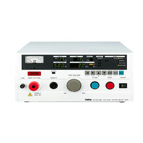
Tsuruga 3587 User manual

#
MODEL 3587
Digital MΩ Tester
Operation Manual
I-02356

MODEL 3587
Contents
1. Preface ····································································· 1
1.1 Preparations prior to use .......................................................................... 2
1.2 Confirmation prior to use ........................................................................ 2
1.3 Warning and caution during measurement ............................................... 3
2. Name of parts ···························································· 4
2.1 Front panel .............................................................................................. 4
2.2 Rear panel ............................................................................................... 5
2.3 Display panel .......................................................................................... 6
3. Operation ································································· 7
3.1 Power supply .......................................................................................... 7
3.2 Connection of test leads .......................................................................... 7
3.2.1 Probe with switch (Model name 5813-23:Option) ......................... 7
3.2.2 HIGH probe (Model name5813-22:Option), LOW probe (Model
name5813-21:Option) ................................................................... 7
3.3 Pre-operation check (Correctness Confirmation of Digital MΩ tester) ..... 8
3.3.1 Preparation .................................................................................... 8
3.3.2 Confirmation Method .................................................................... 8
3.4 Setting flow............................................................................................. 9
3.4.1 MEMORY SET flow ..................................................................... 9
3.4.2 GENERAL SET flow .................................................................. 10
3.4.3 SYSTEM SET flow ..................................................................... 10
3.5 Key lock ............................................................................................... 11
3.6 Memory ................................................................................................ 12
3.7 Memory setting ..................................................................................... 13
3.7.1 Selection of memory ................................................................... 14
3.7.2 Setting of measurement mode...................................................... 14
3.7.3 Measurement voltage setting ....................................................... 15
3.7.4 Selection of resistance range ....................................................... 16
3.7.5 Range switching operation of auto range ..................................... 17
3.7.6 Comparator ................................................................................. 18
3.7.7 Timer/mask timer ........................................................................ 19
3.8 Equipment setting ................................................................................. 20
3.8.1 Start input setting ........................................................................ 21
3.8.2 Selection of memory setting by back side control ........................ 21
3.8.3 Sampling rate setting ................................................................... 22
3.8.4 Frequency setting of power supply .............................................. 22
3.8.5 Connection check setting ............................................................. 23
3.8.6 Buzzer setting ............................................................................. 23
3.8.7 Communication setting ................................................................ 24
3.9 System setting ....................................................................................... 25
3.9.1 Automatic discharge function setting ........................................... 25
3.9.2 Contrast setting ........................................................................... 25

MODEL 3587
4. Measurement method ················································· 26
4.1 AUTO/CONTINUE mode ..................................................................... 26
4.1.1 AUTO operation .......................................................................... 26
4.1.2 CONTINUE operation ................................................................ 27
4.2 REMOTE / MANUAL .......................................................................... 28
4.2.1 MANUAL operation (MANUAL) ............................................... 28
4.2.2 Remote 1 operation (REMOTE 1) ............................................... 28
4.2.3 Remote 2 operation (REMOTE 2) ............................................... 28
4.3 Connection check function .................................................................... 29
4.4 Automatic discharge function ................................................................ 30
5. External control ························································ 31
5.1 Control terminal .................................................................................... 31
5.1.1 Terminal arrangement .................................................................. 31
5.1.2 Connection .................................................................................. 32
5.1.3 PNP/NPN switching .................................................................... 32
5.1.4 Input/output signal ...................................................................... 32
5.1.5 Memory operation ....................................................................... 33
5.1.6 External control timing chart ....................................................... 34
5.1.7 Internal circuit configuration ....................................................... 36
6. Communication (RS-232C) ·········································· 37
6.1 Specification ......................................................................................... 37
6.1.1 Communication specification ...................................................... 37
6.1.2 Connecter pin arrangement .......................................................... 37
6.1.3 Operation .................................................................................... 38
6.2 List of communication command and response ..................................... 39
7. Error display ···························································· 45
8 Use in panel-mount ····················································· 46
8.1 Assembly drawing ................................................................................. 46
8.2 External dimensions when fitted with panel-mount bracket ................... 46
9. Maintenance ···························································· 47
10 Failure symptom ······················································ 47
11. Specifications ·························································· 48
11.1 Model name ........................................................................................ 48
11.2 Measuring range and accuracy ............................................................. 48
11.3 General specifications ......................................................................... 49
11.4 Adaptability ......................................................................................... 50
11.5 Table of factory setting ........................................................................ 51
11.6 External dimensions ............................................................................ 52
11.7 Option ................................................................................................. 52

MODEL 3587
This page is blank.

- 1 - MODEL 3587
1. Preface
The Model 3587 is a digital MΩ tester for insulation resistance test of the many types of
household appliances, electronics equipment and parts.
We would like to thank you for your purchase of our MODEL 3587. For safety and proper use
of this product, please carefully read this operation manual before the use.
This product should be handled by persons having good knowledge in electricity.
The following symbol marks are used in this manual for the safety use of the product.
! Warning This is the warning to avoid danger. Severe injure or fatal accident may
occur to the user in case the product is mishandled.
! Caution This is the caution to avoid danger. Minor injury to the user or physical
obstacle may occur in case the product is mishandled.
High Voltage Danger
High voltage is applied in in the tester during test and never touch your
hands in dangerous location.
! Warning
● Do not open the case or modify the main body.
● Never touch the terminals when power is ON. There may be risk of
electric shock.
! Caution
● The instrument may be damaged if testing method not specified by
manufacturer is used. Read the instruction manual carefully and
understand the contents before the use.
● The rated data for warm up is specified for more than 30 minutes.
● To avoid break-down, malfunction or deterioration of life time,
do not use this product in such places where:
◆ exposed to rain, water drops or direct sunlight.
◆ high temperature or humidity, heavy dust or corrosive gas.
◆ affected by external noise, radio waves or static electricity.
◆ where there is constant vibration or shock.
● Store this product at -20 to 70 ℃.
● Wipe off front panel and housing with dry soft cloth. If necessary,
use close with small amount of synthetic detergent for cleaning.
Do not use an organic solvent such as thinner, benzine for front panel
or housing cleaning, which might damage shape and color of front
panel and housing.

MODEL 3587 - 2 -
1.1 Preparations prior to use
●Unpacking
When the tester is delivered, please check whether it conforms to the required specifications
and has not been damaged in transit. If there is any damage on the tester or it does no work in
conformity with the specifications, please inform us of the model and product name.
●Storage
In case of storing the tester for a long time, store it at the place of low humidity and where it is
not exposed to the direct sunlight.
1.2 Confirmation prior to use
● Power supply
Use the tester with the power source voltage within 90 to 250VAC and the frequency 50/60Hz.
When connecting the power supply cable, confirm that the power supply switch is turned OFF.
! Warning
●Set the power switch for the instrument where it can be used very easily.
●Power supply cable
The plug of power supply cable connected to the tester is for 100VAC use. When the tester is
used with 200VAC, replace the plug with appropriate one for 200VAC use. Please connect the
power supply cable to the power supply connector on the rear panel of the tester. The plug of
power supply cable has 3 pins and the round shape pin in the center is for grounding.

- 3 - MODEL 3587
1.3 Warning and caution during measurement
Electric shock accident or malfunction
! Warning
●Check and confirm the cable condition and metal portion of the wire
before use. There is a danger of electric shock if the measuring cable is
broken or the metal portion of the wire is exposed. If some damage is
found, stop using it immediately and replace the specified new one.
●In order to prevent the electric shock accident or the failure of this unit,
do not apply voltage to the measurement terminal.
●In order to prevent the failure, conduct the measurement after turning off
the power related to the measurement.
●A high voltage is passed through the measuring cable. Never touch the
tip of the measuring cable to avoid the electric shock.
●In order to avoid electric shocks and to ensure the safety of the tester,
protective earth connection is necessary. Connect the supplied power
cord with ground insulating type bipolar outlet.
●When the tester is used, use the supplied power cord by the
manufacturer only. If the power cord not specified by manufacturer is
used, it may be the cause of fire.
Connection of the control cable and communication cable
! Caution
●Use the specified cable size to connect the control terminal.
●Make sure that communication cable and control cable are connected
surely. If the connection is not undertaken correctly, it may cause of the
failure to satisfy specification or malfunction.
●Power supply must be turned off on each device before connection of
communication cable and control cable. Failure to turn of the electric
power cause the electric shock or malfunction.
●Do not change the logic switching (PNP / NPN) of the control terminal
while the power supply is turned on. Set the logical switch (PNP / NPN)
suitable to the external device.
Other caution
! Caution
●If power supply is done by UPS(Uninterruptible power supply device)
or DC-AC inverter, do not use rectangular wave or pseudo rectangular
wave output of UPS or DC-AC inverter. If used, this may cause the
malfunction of the instrument.
●The power supply frequency setting is necessary to eliminate the
induced voltage of power supply. Setting the suitable power frequency
of the power supply in instrument before use.

MODEL 3587 - 4 -
2. Name of parts
2.1 Front panel
①Measuring
terminal
HIGH:+Measuring terminal When the sample to be measured is ground, it is to be
connected to the grounded side of the sample.
LOW:-Measuring terminal To be connected to the non-grounded side of the
sample.
GUARD:LOW(Side) The terminal to guard the leak current of LOW
! Caution
If the HIGH terminal is short circuited to the ground, the
LOW terminal becomes high voltage, which is very dangerous.
Do not touch the measuring terminal during the measurement
(TEST lights up).
②Remote input
When the start input is set to REMORE 2, connect a probe with a switch (Option).
It becomes effective during setting of REMORE 2 only.
This is an input that controls ON / OFF of measurement voltage.
③Display Portion This is green graphic display.
It displays the measured value and various settings, etc.
④TEST LAMP Test lamp lights up during measurement. It blinks during the automatic discharge
function.
⑤START KEY Start key is turned on to start the measurement.
⑥STOP KEY Stop key is used to stop the measurement.
⑦Judgement lamp HIGT:Red lamp is lit up when the measured value exceeds the high limit value.
GOOD:Yellowish green lamp is lit up with a good judgement.
LOW:Red lamp is lit up when the measured value exceeds the low limit value.
⑧Function key F1 to F4 these keys are used to set various measurement conditions and comparators.
HIGH
GOOD
LOW
START STOP
3587MODEL
LOW REMOTE
GUARD
HIGH
[ SET ] [ ] [ LOCK ]
MΩ
12.34
99.9 s 99.9 s
TIMER MASK
999.9
000.0
MΩ
No.10 1000V 2000 MΩ M
F3F2F1
1
2
3 45 6
7
HI SET
LO SET
MΩ
8
TEST
[RCL]
F4

- 5 - MODEL 3587
2.2 Rear panel
⑨Power supply switch Power supply ON/OFF switch
⑩Power inlet Connect the supplied power supply cord. Use the power supply voltage and
frequency within the specified range.
⑪Rear measuring
terminal
HIGH:+Measuring terminal When the sample to be measured is ground, it is to be
connected to the grounded side of the sample.
LOW:-Measuring terminal To be connected to the non-grounded side of the
sample.
! Caution
If the HIGH terminal is short circuited to the ground, the
LOW terminal becomes high voltage, which is very dangerous.
Do not touch the measuring terminal during the measurement
(TEST lights up).
⑫Connection check
terminal
Terminal for checking the contact status of the contact probe.
⑬RS-232C connecter Connector for RS-232C communication
⑭P/N Selector switch Switch to select the external control and BCD output of sink (NPN) and source
(PNP)
⑮Input and output
terminal
Terminals for external control
⑯Interface board mounting part
For BCD Interface board Installation part
100-240V 50-60Hz
AC LINE 28VA MAX
O-COM
GO
LO
HI
CHG
C-ERR
TEST
I-COM
MEM1
MEM2
MEM4
MEM8
START
RESET
CONTROL
PN
RS-232C
LOW
HIGH
L CONTACT
H CONTACT
9
10
13 14 15
16 12 11

MODEL 3587 - 6 -
2.3 Display panel
⑰Memory No. Displays memory No. (No.1 to No.10)
⑱Measurement
voltage
Displays the output voltage setting (25V to 1050V)
⑲Resistance range Displays the resistance range (2MΩ, 20MΩ, 200MΩ, 2000MΩ, AUTO)
⑳Start/On line
display
Displays the status of the start input and the online status of RS-232C
Start input
“M” :MANUAL
“R1” :REMOTE 1
“R2” :REMOTE 2
Status of online
“” :RS-232C communication function ON
㉑Measured value Displays the measured value
㉒Comparator Displays the measured value of HIGH and LOW comparator
㉓Function Displays the function guide of F1 to F4.
F4 displays the status of key lock.
Key lock ON/OFF can be done by press for more than 3 s. Reverse display is shown
during key lock condition.
2000 MΩ1000VNo.10
MΩ
000.0
999.9
MASKTIMER
99.9 s99.9 s
12.34
MΩ
[LOCK][][SET]
HI SET
LO SET
MΩ
17 18 19 20
22
21
23
[RCL]
M

- 7 - MODEL 3587
3. Operation
3.1 Power supply
First confirm the power OFF of the switch located at the rear panel of the instrument and
connect cord to the power supply. Then, ON the power supply switch. This instrument
becomes in operation condition immediately but it is preferred for preheating 30 minute
before the use.
As this instrument is equipped with a parameter holding function, following (1) to (4)
status can be memorized even though the power supply is turned OFF.
(1)10 sets of memories (Measurement voltage, Resistance range, Comparator
setting, Measurement condition of timer etc.)
(2)Key lock state
(3)Start input setting (REMOTE/MANUAL)
(4)Various types of setting
3.2 Connection of test leads
! Caution
This tester comes under the measurement category 0. Do not use the tester for the
measurement of the circuit having measurement category of Ⅱ, Ⅲ and Ⅳ.
For the safety, please use the test lead prescribed by maker only.
If the HIGH terminal is short circuited to the ground, the LOW terminal becomes high
voltage, which is very dangerous.
Do not touch the testing lead by hand during the measurement.
It may cause electric shock during connection and disconnection of testing leads. Turn
OFF the power supply to instrument.
3.2.1 Probe with switch (Model name 5813-23:Option)
Remote measurement operation is performed with the switch built in probe.
Insert the red plug of the probe with switch to the HIGH terminal (red), the remote plug
to the REMOTE terminal, and the black cable to the LOW terminal (black) respectively.
3.2.2 HIGH probe (Model name5813-22:Option), LOW probe (Model name5813-21:Option)
Insert HIGH probe into HIGH terminal (red) and LOW probe into LOW terminal (black)
respectively.
-
ON OFF
LOW
REMOTE
GUARD
HIGH
Red
Black
LOW
REMOTE
GUARD
HIGH
Red
Black

MODEL 3587 - 8 -
3.3 Pre-operation check (Correctness Confirmation of Digital MΩ tester)
The following pre-operation checks are recommended before the measurement start.
3.3.1 Preparation
Resistor ︓Calibration resistors MODEL 5804 Series(option)or any other resistor
having same type of resistance designed for the calibration of Digital MΩ
tester.
Model Resistance
value
5804-11 1MΩ
5804-12 10MΩ
5804-13 100MΩ
5804-14 1000MΩ
Specification of recommended calibration resistor
Max. Circuit
Voltage DC1500V
Tolerance ± 1%
Temp. Coeff. ±50ppm/℃
But for 1000MΩ:±100ppm/℃
Connecting
terminal
Johnson 12mm Terminal
Red color
! Caution
In case of commercially available resistor usage:
・Depending on the test voltage, if the rated voltage or power
of the resistor is exceeded, the resistor may be damaged.
・It is recommended to use the resistor within approximately
50% of the rated power.
3.3.2 Confirmation Method
(1)Suitable resistor is selected.
(2)Set measurement voltage to 500V and measurement range to AUTO in Digital MΩ
tester
(3)Connect the resistor and Digital MΩ tester by means of test lead.
(4)Measurement is started and make sure that the measured display value lies within
the accuracy (Accuracy of the measurement instrument+tolerance of the resistor)
of the resistor.
MODEL 5804

- 9 - MODEL 3587
3.4 Setting flow
3.4.1 MEMORY SET flow
SYSTEM SET F4[ENT]
GENERAL SET F4[ENT]
MEMORY SET
F4[LOCK]
F1[SET]
F4[ENT]
F2[RCL]
F1[SEL]
F1[SEL]
F1[SEL]
Measurement screen flow
Initial screen after power onMeasurement screen
Memory selection from No. 1 to 10
Invalid key operation from F1 to F3
Setting screen SETTING MODE
3.4.1 Refer to MEMORY SET flow
3.4.2 Refer to GENERAL SET flow
3.4.3 Refer to SYSTEM SET flow
MEMORY No 1
TEST MODE AUTO
VOLTAGE 1000V
RANGE 2000MΩ
F4[ENT]
F4[ENT]
HIGH SET 9990MΩ
LOW SET 0020MΩ
COMP RNG 2000MΩ
F4[ENT]
TIMER 10.0s
MASKTIMER 00.5s
MEMORY SET 1/3
MEMORY SET 2/3
MEMORY SET 3/3
Fanction
to measurement screen
Memorize and return
Note: When RANGE is selected, if F1「SEL」key is
Fanction
Fanction
to measurement screen
Memorize and return
to measurement screen
Memorize and return
Note: When COMP RNG is selected, if F1「SEL」key is
Note: When MASK TIMER is selected, if F1「SEL」key is
Measurement screen
Contents
Contents
Contents
F1[SEL] Operation of function (Downward only)
F2[▲]、F3[▼] Switching between contents
pressed, 2/3 of the screen is switched
pressed, 3/3 of the screen is switched
pressed, 1/3 of the screen is switched
to MEMORY SET.
to MEMORY SET.
to MEMORY SET.
F2[▲]、F3[▼] Switching between contents

MODEL 3587 - 10 -
3.4.2 GENERAL SET flow
3.4.3 SYSTEM SET flow
F4[ENT]
F4[ENT]
F4[ENT]
10.0s
REMOTE MANUAL
EXT.CTRL OFF
SAMPLING FAST
POWER FRQ 60Hz
CNTCT CHK ON
BUZZ MODE OFF
BUZZ VOL 1
ONLINE
RS BPS 19200BPS
RS PRITY NONE
GENERAL SET 1/3
GENERAL SET 2/3
GENERAL SET 3/3
Measurement screen
Function
to measurement screen
Memorize and return
to measurement screen
Memorize and return
to measurement screen
Memorize and return
Function
Function
Note: When POWER FRQ is selected, if F1「SEL」key
is pressed, 2/3 of the screen switches to
Note: When BUZZ VOL is selected, if F1「SEL」key
is pressed, 3/3 of the screen switches to
Note: When RS PARITY is selected, if F1「SEL」key
is pressed, 1/3 of the screen switches to
MEMORY SET.
MEMORY SET.
MEMORY SET.
Contents
Contents
Contents
F1[SEL] Operation of function (Downward only)
F2[▲]、F3[▼] Switching between contents
F4[ENT]
DISCHARGE DISABLE
CONTRAST 3
SYSTEM SET
Measurement screen
Fanction
to measurement screen
Memorize and return
Contents
F1[SEL] Operation of function (Downward only)
F2[▲]、F3[▼] Switching between contents

- 11 - MODEL 3587
3.5 Key lock
It is a switch that prohibits operation of the instrument from the front panel in order to
avoid the measurement by unintentional change of setting. But, key lock can’t be set in
START key, STOP key and probe with switch. Display of the LOCK back ground
changes during key lock condition. If other key are required to use during key lock
condition, key lock must be released first to use the other keys.
●Key lock method
Press F4 [LOCK] key for more than 3 s.
Display of the back ground of LOCK changes which shows that instrument is in
locked condition.
●Cancellation of key lock
During the key in locked condition, press F4 [LOCK] key for more than 3 s.
Key lock will be released.
HIGH
GOOD
LOW
START STOP
3587MODEL
LOW
REMOTE
GUARD
HIGH
[SET] [ ]
MΩ
12.34
99.9 s 99.9 s
TIMER MASK
999.9
000.0
MΩ
No.10 1000V 2000 MΩ M
F3F2F1
LOCK
HI SET
LO SET
MΩ
TEST
[RCL]
F4

MODEL 3587 - 12 -
3.6 Memory
This instrument is equipped with 10 pairs of memories that store comparator and
measurement conditions. The following 4 items, 8 types are available for memory
storage.
Measurement mode (AUTO, CONTINUE)
Measurement range (Measurement voltage, Resistance range)
Setting of comparator (Upper value and lower value, Range )
Setting of timer (Timer, Mask timer)
Note: Setting can’t be cone in ONLINE condition.
Memory selection signal can’t be selected during valid period.
Selection can’t be done during measurement.
[Selection of memory]
●Front panel method
Call
When F2 [RCL] key (①) is pressed in standby state, memory no. will increased and
setting call will be displayed.
Memory from 1 to 10 can be selected.
●External control method
Refer to memory operation (5.1.5) for detail information.
[Memory registration]
After selecting the memory no. you want to register, select measurement mode,
measurement range, comparator, timer etc. with MEMORY SET.
HIGH
GOOD
LOW
START STOP
3587MODEL
LOW
REMOTE
GUARD
HIGH
[ SET ] [ ] [ LOCK ]
MΩ
12.34
99.9 s 99.9 s
TIMER MASK
999.9
000.0
MΩ
No.10 1000V 2000 MΩ M
F3F2F1
1
HI SET
LO SET
MΩ
TEST
[RCL]
F4

- 13 - MODEL 3587
3.7 Memory setting
Input of MEMORY SET
① Press F1 [SET] key in standby state.
Display changes to SETTING MODE.
② Press F1 [SEL] key to select MEMORY SET.
Memory setting can be changed by pressing F4 [ENT] key.
Basic operation
Memory No., measurement mode, measurement voltage, resistance range, comparator,
timer, mask timer can be set.
Operation key
F1 [SEL] : Selection of setting item.
The back ground of the display color of the selected item will be
changed.
F2 [▲] : Change of setting values
F3 [▼] : Selection of setting from TEST MODE ,RANGE ,COMP RNG
setting value can be increased or decreased by numerical setting.
F4 [ENT] :Memorize the setting and the display returns to measurement
standby state.
HIGH
GOOD
LOW
START STOP
3587MODEL
LOW
REMOT E
GUARD
HIGH
[]
F3F2F1
SETTING MODE
SYSTEM SET
EXT. POLARITY : NPN
[ENT]
1
2
MEMORY SET
TEST
[RCL][SEL]
F4
GENERAL SET
HIGH
GOOD
LOW
START STOP
3587MODEL
LOW
REMOTE
GUARD
HIGH
F3F2F1
[ ENT ]
MEMORY SET
MEMORY No
TEST MODE
VOLTAG E
RANGE
AUTO
1000V
2000MΩ
1/3
[][]
1
TEST
[SEL]
F4

MODEL 3587 - 14 -
3.7.1 Selection of memory
① Press F1 [SEL] key to select the MEMORY No.
② Select the Memory No.by F2 [▲], F3 [▼] key.
③ Press F4 [ENT] to memorize the setting and the display returns to measurement
standby state.
To continue the other setting, select the items that you want to change by pressing
F1 [SEL]
3.7.2 Setting of measurement mode
CONTINUE mode to undertake the measurement continuously and timer which measures
the time can be selected by AUTO mode.
① Press F1 [SEL] key to select the MEMEORY SET and press F4 [ENT] key to enter it.
Select TEST MODE by F1 [SEL] key.
② Press F2 [▲], F3 [▼] key.to select AUTO/CONTINUE.
③ Press F4 [ENT] to memorize the setting and the display returns to measurement
standby state.
To continue the other setting, select the items that you want to change by pressing
F1 [SEL]
HIGH
GOOD
LOW
START STOP
3587MODEL
LOW
REMOTE
GUARD
HIGH
F3F2F1
[ ENT ]
MEMORY SET
MEMORY No
TEST MODE
VOLTAG E
RANGE
1
1000V
2000MΩ
1/3
[][]
AUTO
TEST
[SEL]
F4
HIGH
GOOD
LOW
START STOP
3587MODEL
LOW
REMOTE
GUARD
HIGH
F3F2F1
[ ENT ]
MEMORY SET
MEMORY No
TEST MODE
VOLTAG E
RANGE
AUTO
1000V
2000MΩ
1/3
[][]
1
TEST
[SEL]
F4

- 15 - MODEL 3587
3.7.3 Measurement voltage setting
① Press F1 [SEL] to select MEMEORY SET and press F4 [ENT] to enter it.
Select VOLTAGE by F1 [SEL] key.
② Press F2 [▲], F3 [▼] key.to change the setting
If keys are pressed continuously, the speed of setting value changes in 3 steps.
Setting range 25V to 1050V
③ Press F4 [ENT] to memorize the setting and the display returns to measurement
standby state.
When the measurement range is out of range, OUT OF RANGE is displayed for about
1 s and display returns to setting mode.
Set the measurement voltage or measurement range within the range of Table 3.1.
To continue the other setting, select the items that you want to change by pressing
F1 [SEL].
Table 3.1 Voltage setting and resistance range
Measurement
voltage setting Resistance range
25V to 99V 2MΩ, 20MΩ, 200MΩ, AUTO
100V to 499V 2MΩ, 20MΩ, 200MΩ, 2000MΩ, AUTO
500V to 1050V 20MΩ, 200MΩ, 2000MΩ, AUTO
HIGH
GOOD
LOW
START STOP
3587MODEL
LOW
REMOTE
GUARD
HIGH
F3F2F1
[ENT]
MEMORY SET
MEMORY No
TEST MODE
VOLTAGE
RANGE
1
AUTO
2000MΩ
1/3
[][]
1000V
TEST
[ SEL ]
F4

MODEL 3587 - 16 -
3.7.4 Selection of resistance range
① Press F1 [SEL] key to select MEMEORY SET and press F4 [ENT] key to enter it.
Select RANGE by F1 [SEL] KEY.
② Press F2 [▲], F3 [▼] key to change the setting
③ Press F4 [ENT] to memorize the setting and display returns to measurement standby
state.
When the resistance range is out of range, OUT OF RANGE is displayed for about 1 s
and display returns to setting mode.
Set the measurement voltage or measurement range within the range of table 3.1.
To continue the other setting, select the items that you want to change by pressing F1
[SEL].
Table 3.2 Display range for resistance range
Measurement
voltage Resistance range Display range
25V to
99V
2.000MΩ 0.000 to 4.990 ※ 1
20.00MΩ 1.79 to 49.90 ※ 2
200.0MΩ 17.9 to 999.0 ※ 3
100V to
499V
2.000MΩ 0.000 to 4.990 ※ 1
20.00MΩ 1.79 to 49.90 ※ 2
200.0MΩ 17.9 to 499.0 ※ 2
2000MΩ 179 to 9990 ※ 3
500V to
1050V
20.00MΩ 0.00 to 49.90 ※ 1
200.0MΩ 17.9 to 499.0 ※ 2
2000MΩ 179 to 9990 ※ 3
※ 1,2 When count is exceeded 4990, OVER is displayed.
※ 2,3 When the count is less than 179, UNDER is displayed.
※ 3 When count is exceeded 9990, OVER is displayed.
HIGH
GOOD
LOW
START STOP
3587MODEL
LOW
REMOTE
GUARD
HIGH
F3F2F1
[ENT]
MEMORY SET
MEMORY No
TEST MODE
VOLTAGE
RANGE
1
AUTO
2000MΩ
1/3
[][]
TEST
1000V
[ SEL ]
F4
Table of contents
Other Tsuruga Test Equipment manuals