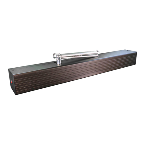
Tucker KP evo User manual

920.1044
KP evo -TAP CONTROLLER


920.1044 | 01
IMPORTANT
READ THIS SECTION BEFORE PROCEEDING WITH INSTALLATION
Tucker Auto-Mation,LLC (hereafter referred to as “Tucker”) recommends that all of its automated
pedestrian door products be installed by atrained automatic door technician and that the resulting
performance of the product be in full compliance with the most current version of the American
National Standards Institute document A156.10 or A156.19 (whichever is applicable) as well as any
applicable building codes and/or re codes.Tucker further recommends that afull inspection of the
operating system be performed in accordance with the guidelines of the American Association of
Automatic Door manufacturers (AAADM).This inspection must be performed by acertified AAADM
trained inspector.Tucker recommends this documented inspection be performed upon completion
of the installation as well as, following the completion of every service call thereafter.If service is
not performed within one year of the previous service action, aroutine AAADM inspection should
be performed and documented.Under no circumstance should the product operate for more than
one year without an AAADM inspection.Tucker does NOT recommend installation or service, on
any of their automated pedestrian door products, by any individual who is not certified as an
AAADM inspector.Following the installation or service of any Tucker automated pedestrian door
product, if it is deemed unsafe, or is operating in an unsatisfactory manner according to national
performance standards or recommended performance guidelines as defined by Tucker, repairs
should be made immediately.If an immediate repair cannot be made, the product should be
disabled, and appropriate measures should be taken to secure the door in asafe position or to
enable the door to safely be used manually.During this situation, every effort should be made to
notify the owner (or person responsible) of the condition and to advise on corrective actions that
must be taken to return the product to safe operation.
KP evo -TAP CONTROLLER

TABLE OF CONTENTS
1. KP EVO ……………………………………………
1.1 Installation and connections ……….
1.2 Switching on and the home screen
1.3 SELECTION menu ………………………..
1.4 FUNCTIONS menu ……………………….
2. DIAGNOSTICS ……………………………………
2.1 LEDs check ……………………………………
I/O board LEDs ……………………………..
Logic board LEDs ………………………….
2.2 Inputs and outputs status check …..
2.3 Automation status check ………………
2.4 Warnings ………………………………………
2.5 Errors ……………………………………………
2.6 Other board data ………………………….
2.7 Firmware versions ………………………..
2.8 Log Data ……………………………………….
3. UPLOAD / DOWNLOAD …………………….
4. PUT TING INTO SERVICE ……………………
4.1 Final checks ………………………………….
4.2 Final operations …………………………..
Installing an aluminum cover ………………
5. MAINTENANCE …………………………………
5.1 Inserting / replacing the battery ……
5.2 Replacing the fuse …………………………
5.3 Routine maintenance …………………..…..
6. INTERCOM ………………………………………..
6.1 Intermode …………………………………….
6.2 Interlock ……………………………………….
Interlock with no memory ………………….
Interlock with memory ……………………….
6.3 2 Leaves ………………………………………..
6.4 2 Leaves + Interlock ………………………
7. COMPANY ADDRESS …………………………
3
3
4
5
6
14
14
14
14
15
15
15
16
18
18
18
19
20
20
20
21
21
21
21
22
23
24
24
25
25
25
25
26
AKP EVO menu ………………………………………………
BAccess permissions and passwords ……………..
CI/O board LEDs …………………………………………….
DLogic board LEDs ………………………………………….
EStatus ………………………………………………………….
FWarnings ……………………………………………………..
GErrors …………………………………………………………..
HSelecting the upload/download function …….
IScheduled maintenance ………………………………
7
14
14
14
15
16
17
18
21
920.1044 | 02

1. KP evo
1.1 INSTALLATION AND CONNECTIONS
-------------------------------------------------------------------------------------------------------------------------------------------
CARRY OUT THE FOLLOWING OPERATIONS WITH
THE ELECTRICITY SUPPLY DISCONNECTED
-------------------------------------------------------------------------------------------------------------------------------------------
1. Disassemble the parts (01).
2. Break the cable passage insert.
-------------------------------------------------------------------------------------------------------------------------------------------
With reference to 02, the KP EVO is designed
for the cables to enter from the back (1) or from
underneath (2).
-------------------------------------------------------------------------------------------------------------------------------------------
3. Decide where to position the support and x it
using suitable screws (01 -1).
4. Connect the KP EVO to the 950N2 using a 4 pair
twisted U/UTP AWG24 cable with a maximum
length of 50m (03).
-------------------------------------------------------------------------------------------------------------------------------------------
An optional key device can be connected between
terminals G and K in order to enable/disable the
KP EVO.
-------------------------------------------------------------------------------------------------------------------------------------------
5. Reassemble the parts indicated in (01).
920.1044 | 03

1.2 SWITCHING ON AND THE HOME SCREEN
1. Turn power on to the 950N2
2. The display will show the following in sequence:
920.1044 | 04
in which the Bootloader version appears, then
in which the firmware version appears, and lastly
The content of this home screen, including the
fixed icons and those that may appear under
certain circumstances, is explained in 04.
3. The 4 buttons are used to select controls that,
depending on the screen, appear on the display
above them.
4. By pressing the relative button on the home screen
(04) you can:
= set the NIGHT mode
= set the MANUAL mode
= switch to the FUNCTIONS menu that includes
all the 950N2 configuration parameters.
= switch to the SELECTION menu that includes
additional operating modes.
---------------------------------------------------------------------------------------------------------------------------------------
By pressing the button to set the NIGHT or
MANUAL mode, the relative icon is highlighted
and the description of the operating mode is
updated on the display.Once MANUAL mode
has been set by pressing the relative button,
press it again to return to the previous mode.
--------------------------------------------------------------------------------------------------------------------------------------

1.3 SELECTION MENU
To access the SELECTION menu from the home
screen, press the button (05).
4. New icons appear on the display that dene the
operating modes that can be set.The possible
combinations can be obtained by pressing the
corresponding buttons (05). After having set the
operating mode, press the OK button to confirm and
return to the home screen.
---------------------------------------------------------------------------------------------------------------------------
The description of the operating mode on the
display is updated with the description of the
one that has been set.
---------------------------------------------------------------------------------------------------------------------------
920.1044 | 05

1.4 FUNCTIONS MENU
To ac cess the FUNCTIONS menu from the ho me screen,
press the button (06).
The display prompts for a 4-digit password to be
entered.
---------------------------------------------------------------------------------------------------------------------------
The factory-set password is: 0000
---------------------------------------------------------------------------------------------------------------------------
-Set the first digit using the and buttons.
-Confirm using the OK button to move to the next digit.
-When all 4digits have been entered, if the password
is correct, access the FUNCTIONS menu as aUSER or
aTECHNICIAN.
-Select the item from the menu using the and
buttons.
-Confirm using the OK button to enter.
---------------------------------------------------------------------------------------------------------------------------
Press ESC at any time to return to the
home screen.
---------------------------------------------------------------------------------------------------------------------------
920.1044 | 06

920.1044 | 07

920.1044 | 08

920.1044 | 09

920.1044 | 10
■PROGRAMMING INPUTS/OUTPUTS INPUTS
The inputs on terminal board J5 of the I/O board can be
conjured with the following functions
-----------------------------------------------------------------------------------------------------------------------------------------
Each input can be set to NC or NO according to
the device connected to it.
------------------------------------------------------------------------------------------------------------------------------------------
DISABLED
No associated function.
EXTERNAL OPEN
When activated, the door opens and remains open as long
as the input is active.When released, the door waits for
the pause time to elapse and then closes.This has no
effect in the EXIT ONLY or NIGHT modes.
INTERNAL OPEN
When activated, the door opens and remains open as long
as the input is active.When released, the door waits for
the pause time to elapse and then closes.This has no
effect in the ONLY IN or NIGHT modes.
AUTOMATIC OPEN
When activated, the door opens and remains open as long
as the input is active.When released, the door waits for
the pause time to elapse and then closes.Active in the BI-
DIRECTIONAL, EXIT ONLY and ONLY IN modes.This has no
effect in the NIGHT mode.
SEMIAUTOM.OPEN
When activated:
-if the door is not already open, it opens and remains
open
-if the door is already open, it closes
Active in the BI-DIRECTIONAL, EXIT ONLY and ONLY IN
modes.This has no effect in the NIGHT mode.
KEY
When activated, the door opens and remains open as
long as the input is active.When released, the door
waits for the night pause time to elapse and then
closes.Active in the BI-DIRECTIONAL, EXIT ONLY, IN
ONLY and NIGHT modes.
PARTIAL OPEN
Only opens the master door when activated in the “2
leaves” mode.
CLOSING SAFETY
When activated:
-If the door is closing, it reopens
-If the door is already open, it prevents it from closing
-If the door is opening, it has no effect
OPENING SAFETY
When activated:
-If the door is opening, it stops until it is released
-If the door is already closed, it prevents it from
opening
-If the door is closing, it has no effect

920.1044 | 11
EMERGENCY OPEN
When activated, the door opens (always total) and
remains open as long as the input is active.When
released, the door waits for the night pause time to
elapse and then closes.Also active in NIGHT mode.
EMERGENCY OPEN WITH MEMORY
When activated, the door opens (always total) and
remains open as long as the input is active.When
released, the door remains open until it is Reset
EMERGENCY CLOSE
When activated, the door closes and remains closed as
long as the input is active.When released, the door
returns to normal operation.
EMERGENCY CLOSE WITH MEMORY
When activated, the door closes and remains closed as
long as the input is active.When released, the door
remains closed until it is Reset
FIRE ALARM
When activated, the door closes, regardless of the
operating mode that has been set, with the lock kept in
the released position.It has priority over any commands
that may be active.
ALWAYS OPEN
When activated, the ALWAYS OPEN mode is set.
EXIT ONLY
When activated, the EXIT ONLY mode is set.
ENTRY ONLY
When activated, the ONLY IN operating mode is set.
NIGHT
When activated, the NIGHT mode is set.
MANUAL
When activated, the MANUAL mode is set.
PARTIAL
When activated, the PARTIAL mode is set.
INTERLOCK ON
When activated, the INTERLOCK mode is set.
TIMER
When activated, the TIMER mode is set.
OUTPUTS
The outputs on terminal board J5 of the I/O board can be
configured with the following functions
------------------------------------------------------------------------------------------------------------------------------------------
Each input can be set to NC or NO according to
the device connected to it.
------------------------------------------------------------------------------------------------------------------------------------------
DISABLED
No associated function.
GONG
The output is activated and deactivated at 1-second
intervals when the safety devices are engaged.
ERROR
The output is activated if there is an error.
EMRG.ACTIVE
The output is activated when an Emergency is
triggered.
TEST
The output commands aFAILSAFE test on the inputs
that are conjured as safety devices on which the option
of running aTEST before movement has been enabled.
DOOR NOT CLOSED
The output remains active until the door is closed.
DOOR OPEN
The output remains active as long as the door is open.
DOOR OPENING
The output remains active as long as the door is
moving.
LIGHT
The output is activated, for aprogrammable length of
time, when the door is open in NIGHT mode.
INTRUSION ACTIVE
The output is activated when an intrusion is in progress
(i.e. when an unexpected movement of the door from
its closed position is detected).
CLOSING SAFETY
The output is activated when a closing safety device is
active.
SAFETIES
The output is activated when a closing or opening
safety device is engaged.
OP/CL RELAY
Species the logic of the door status relay (NC/NO).
EXTERNAL SELECTOR
Species the operating mode associated with positions 1
and 2 of the selector on the side of the unit.
■PROGRAMMING –TIMING
PAUSE TIME
Denes the pause time of the door when opened by a
command, before closing automatically.
PAUSE TIME P&G
Sets the door pause time when opened by a Push & Go
command, before closing automatically.
NIGHT PAUSE TIME
Sets the door pause time when opened by a command
in NIGHT mode, before closing automatically.

920.1044 | 12
NIGHT SENSOR DELAY
When NIGHTmode is set, the internal detector remains
active for the amount of time set in this parameter, to
allow it to be opened only once.The internal detector is
disabled immediately after opening and in any case upon
expiry of the set delay.
■PROGRAMMING –MOTOR BLOCK KIT
FUNCTION
Species the operating mode in which the lock is activated.
LOCK DELAY
Species the opening delay time of the door to allow the
lock to be released, particularly motorized locks.
RELEASE TYPE
Species when power is disconnected from the lock after it
has been mechanically released:
Opening =during the opening phase
Closed =when the door is closed again
■PROGRAMMING INSTALLATION ARM TYPE
Species the type of transmission arm installed (shoe or
articulated)
START SETUP
Carries out aSetup cycle after confirmation.
PUSH AND GO
Sets the function that commands the automatic opening
of the door after an initial manual push:
Disabled =Push &Go not enabled
Enabled =Push &Go enabled
Fast food =Push &Go enabled in “FAST FOOD“mode
(manual opening, motorized closing)
PARTIAL STOP SEC.
Species the detection area of the safety in opening:
Disabled= obstacle detection active over the entire
opening stroke
Enabled=obstacle detection NOT active in proximity to
the opening stop
LEAF DELAY
Species the opening delay between the doors of 2leaf
models.
SCP
Species the function that pushes the door with agreater
force in the final section of the closure.It is useful to
activate this function if there is high friction, if the seals
are particularly rigid or if locks have astiff latch.
------------------------------------------------------------------------------------------------------------------------------------
Because activating the SCP function also
reduces the sensitivity of the electronic anti-
crushing system in the final section of closing,
DO NOT activate theSCP function in "low
energy" mode.
-----------------------------------------------------------------------------------------------------------------------------------
REVERSE STROKE
Sets the function that makes the door carry out a short
reverse stroke before opening to make it easier to the
release the lock.
2 EASY REG.
Registration of BUS 2easy devices.
INOUT STATE
The display indicates the status (on / o) of inputs I1-I8
and outputs O1-O2 in real-time.
DOOR STATUS
The display indicates the status of the automation in
real-time.
OTHER BOARD DATA
The display indicates useful diagnostics information in
real-time.
■PROGRAMMING -INTERCOM
FUNCTION
Sets the operating mode.
MASTER/SLAVE NR.
Sets the network ID of the unit.
INTERCOM REG.
Registers the units of the network (to be performed
only on the 950N2 with ID1).
NODE LIST
Shows the ID of the units registered (on the master).
■PROGRAMMING –MISCELLANEOUS
CONFIG. DEFAULT
Shows whether the parameters have been modified,
and if so, resets the factory defaults after confirmation.
BOARD'S DISPLAY
Not active.
INTRUSION
Sets the function in which the door resists attempts to
open it manually.

920.1044 | 13
KPEVO KEY
You can choose between:
Block =the user must enter the user password in order to
access the menus that he is authorized to use.
Without user psw =the user doesn’t need to enter the
user password in order to access the menus that he is
authorized to use.
CONSECUTIVE OBST.
Species the maximum number of consecutive obstacle
detections in the same direction of movement, before
stopping in an error condition.
TEST ERROR
Species the effect that the TEST will have when it detects
asafety device fault:
Disabled =the door will remain stationary in an error
condition
Enabled =the door will continue to operate at minimum
speed
■ERRORS
In this menu, the display indicates any current errors that
there may be in real time.
■WARNINGS
In this menu, the display indicates any current alerts that
there may be in real time.
■CYCLE COUNTER
The 950N2 has two counters:
-total, non-resettable
-partial, resettable
This menu allows you to view the cycles performed by the
automation and reset the partial counter.
It is also possible to set adeadline for scheduled
maintenance according to:
-date (optional)
-number of cycles (from 1000 to 1000000)
Alert 60 will be displayed as soon as one of the two
settings (date or number of cycles) is reached.
------------------------------------------------------------------------------------------------------------------------------------
Logging in with the user password only allows
data to be viewed.
-----------------------------------------------------------------------------------------------------------------------------------
■DATE/TIME
This menu allows you to set or modify the date, time and
turn European summer time on /off.
------------------------------------------------------------------------------------------------------------------------------------
To keep the settings even if there is no mains
power, which is necessary for the TIMER to
work correctly, a battery must be installed on
the Logic board.
-----------------------------------------------------------------------------------------------------------------------------------
■TIMER
This menu includes all the parameters for configuring
the TIMER function.When the TIMER is enabled, the
operating mode of the door during the programmed
time bands is set automatically. A maximum of 6daily
time bands can be defined, and an operating mode,
selected from those available, assigned to each one.
Each time band has astart time and an end time.
The time bands must not overlap.
------------------------------------------------------------------------------------------------------------------------------------
When the TIMER is enabled, the Ticon appears
on the home screen.To manually change the
operating mode set by the TIMER, it first has to
be disabled.In order for the TIMER to work
correctly, abattery must be installed on the
Logic board.
-----------------------------------------------------------------------------------------------------------------------------------
In order to quickly program groups of days of the week
with the same time bands, it is possible to
simultaneously select all the days of the week (MON -
SUN) and all weekdays (MON -FRI).Once the time
bands that have been defined here have been
confirmed using the APPLY option, they will overwrite
any time bands that have already been programmed
for individual days.If it is necessary to program specific
days or periods (e.g. recurring holidays), you may use
the JOLLY function. A maximum of 6JOLLY time bands
can be specified and an operating mode, selected from
those available, assigned to each one.Each time band
has astart time and an end time.The time bands must
not overlap.The JOLLY time bands are then assigned to
amaximum of 6INTERVALS.An interval can be asingle
day or aseries of days.

920.1044 | 14
------------------------------------------------------------------------------------------------------------------------------------------
Logging in with the user password only allows
data to be viewed.
------------------------------------------------------------------------------------------------------------------------------------------
■PASSWORD
This menu allows passwords to be set or modified.
To access the FUNCTIONS menu you are prompted to
enter a 4-digit password.The 950N2 has two passwords
available, with different access rights.(B)
BAccess per missions and passwords
---------------------------------------------------------------------------------------------------------------------------------
The user is only allowed to modify the user
password.
---------------------------------------------------------------------------------------------------------------------------------
2. DIAGNOSTICS
2.1 LEDS CHECK
I/O BOARD LEDS
Each input on the I/O board, has a LED that indicates
the physical state of the contact:
C I / O board LEDs
LED
DL1 Accessories
power on
Accessories
power off
DL2 –DL9 Open contact Close contact
LOGIC BOARD LEDS
The are 4 LEDs on the logic board:
D Logic board LEDs
LED
DL1
green
No USB USB
connect
-ed
§
DL2
red
Normal
conditio
n
error Setup
request
ed
Setup in
progres
s
DL3
blue
No
power
or
board
failure
/
Normal
conditio
n /
DL4
yellow
Board
pa-
rameter
sthe
same as
trimmer
and DIP
Switch
values
Board parameters
Different to button
trimmer and
Pressed DIP switch
values /
Off
On
Flashing
Fast flashing

920.1044 | 15
2.2 INPUTS AND OUTPUTS STATUS CHECK
The status of each input and output can be checked
via the KP EVO.
Go to menu 2.5.9. The display indicates the status of
the logic as shown in 07. Example:
IN1 = input active
IN1 = input not active
2.3 AUTOMATION STATUS CHECK
The current status of the automation system can be
checked via the KP EVO.
Go to menu 2.5.10. The display shows information
regarding the status of the automation.
E STATUS
2.4 WANRINGS
Alerts provide information regarding the status or
current phase of the automation and errors that do
not prevent it from operating. It is possible to check
any current alerts via the KP EVO.
Go to menu 4 to view the list of current alerts.
If there is at least one alert, an icon appears on the
home screen.

920.1044 | 16
F STATUS 2.5 ERRORS
Errors are malfunctions that prevent the automation
system from working.They are indicated by asteady
red LED on the Logic board.After every 5minutes in
which afault condition persists and for amaximum of
20 consecutive times, the 950N2 will perform aReset
to attempt to restore normal operation so as not to
require any action if the condition that caused the
error was temporary.If the fault persists, remove the
cause in order to restore normal operation.The type
of error can be identified via the KP EVO The error
code appears on the home page.Go to menu 5; the
display provides information regarding the current
error.

920.1044 | 17
G ERRORS

920.1044 | 18
2.6 INPUTS AND OUTPUTS STATUS CHECK
Go to menu 2.5.11 of the KP EVO.The display provides
information on the following parameters:
- V MAIN :input voltage to the Logic board (Volts)
- V ACC :output voltage for accessories (Volts)
-POS :position of the rotating shaft (degrees)
- I MOT :current drawn by motor (Amperes)
2.7 FIRMWARE VERSIONS
Go to menu 9of the KP EVO to view the firmware
versions of the bootloader, the Logic board and the
KP EVO.
2.8 LOG DATA
The 950N2 records the last 512 system events. A
battery must be installed on the Logic board in order
to save the list of events in memory even if the system
is switched o. To download the data as atext le, see § .
Table of contents
Other Tucker Door Opening System manuals
Popular Door Opening System manuals by other brands

Green Star
Green Star Touch 'n Hold Smooth installation instructions

Entrematic
Entrematic EM EMSW Installation and service manual

Label
Label Neptis SLT-B user manual

Fleetwood
Fleetwood 3000-T Series Assembly/installation instructions

Karcher Design
Karcher Design EZ1060 Assembly instruction

Eco
Eco TS-61 B Assembly instruction

Assa Abloy
Assa Abloy Norton 9300BCH installation instructions

GEZE
GEZE Slimdrive SL NT GGS Additional installation instructions

IKEA
IKEA UTRUSTA installation instructions

Cal-Royal
Cal-Royal 22-3PT installation instructions

Nice
Nice SWN Series Instructions and warnings for installation and use

Dormakaba
Dormakaba ED100 Mounting instructions