Tuncmatik 5430G User manual

info@tuncmatik.com / www.tuncmatik.com
User Manual
Tuncmatik Mini DC Charger
30-60kW
Electric Vehicle Charger
User Manual

Table of Contents
1. Safety Instructions ................................................................................................... 1
2. Technical Specifications............................................................................................. 3
3. Introduction ............................................................................................................. 5
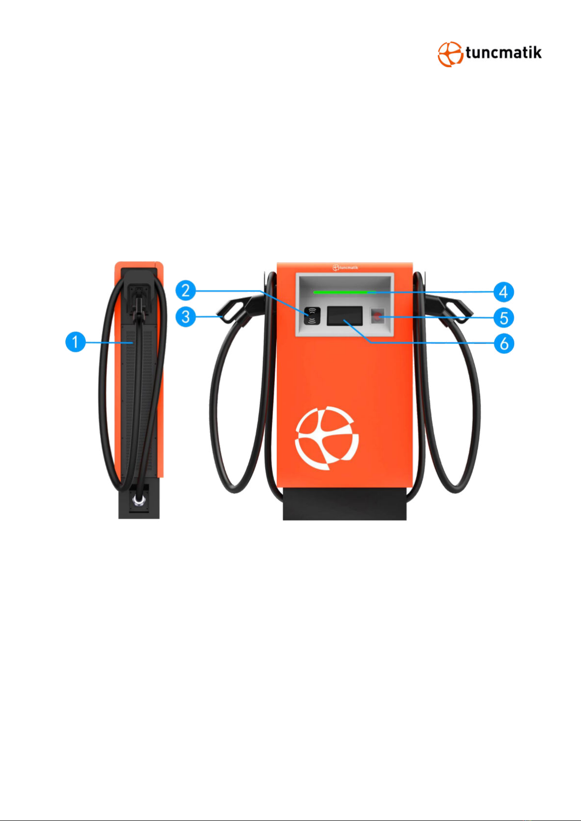
3.1. Product Overview............................................................................................ 5
4. Packaging ................................................................................................................ 6
5. Installation............................................................................................................... 7
5.1. Pre-Installation ............................................................................................... 7
5.2. Cable Reach ................................................................................................... 8
5.3. Construct
Foundation
..................................................................................... 8
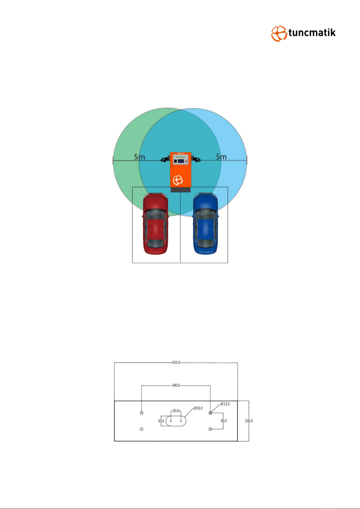
5.4. Dimensioned Drawing ................................................................................... 10
5.5. Space Requirement ....................................................................................... 11
5.6. Installation Steps .......................................................................................... 12
6. Charging Process.................................................................................................... 14
6.1. Charging Process .......................................................................................... 14
6.2. Charging Page Description............................................................................. 18
6.3. LED Operation .............................................................................................. 19
6.4. Precautions .................................................................................................. 19
6.5. EPO Operation .............................................................................................. 20
7. Routine Maintenance .............................................................................................. 21
8. Trouble Shooting .................................................................................................... 22

1
1. Safety Instructions
Read and follow the instructions and warnings in this Manual before attempting to install this
product. Keep this Manual for future reference.
Please follow the below safety precautions to prevent bodily injuries and property
damages.
Warning: When the product is running, it should pay attention to ventilation, heat
dissipation and keep the environment clean. Avoid installation in places with frequent
occurrence of storm, rainstorm, lightning and other severe weather.
Warning: During installation, if any abnormal phenomena such as cracking, loose
case lock, water leakage are showing up, all operations shall be stopped immediately
and professionals shall be informed in time to deal with them.
Warning: Do not put inflammable, explosive or combustible materials, chemicals,
combustible steam and other dangerous goods near the charge pile.
Warning: Please keep the charging plugs clean and dry. If there is any dirt, please
wipe it with a cleaning cadre. It is strictly prohibited to touch the charging core with
hands when it is powered.
Warning: It is strictly prohibited to use the charge pile when the charge plugs or
charging cable is defective, cracked, worn, and the charge plugs line is exposed. If
any, please contact the staff in time.
Warning: In case of rain and thunder, please use electricity carefully. It is better to
stop charging.
Warning: Do not attempt to disassemble, repair or modify the charging station. For
repairs or modifications, please contact the staff. Improper operation may result in
damage, water leakage, electricity leakage, etc.
Warning: It is forbidden to insert and unplug the plug during the charging process
to ensure the safety of life and the vehicle during the charging process.
Warning: It is strictly prohibited to continue to use this product for charging in case
of failure.
Warning: If any leakage or insulation failure occurs during the operation of the
product, please press the emergency power off button immediately.
Warning: Obvious maintenance marks shall be set up. Isolation and protection
measures shall be added to live parts that may be near by operators to avoid contact.

2
CAUTIONS
CAUTION: Wrong installation and testing of the charger will cause potential damage
to the vehicle battery, assembly, and the charger itself.
CAUTION: Do not operate the charger in temperatures outside its operating range
of -35°C to +55°C.
NOTE:
Electrical equipment should only be installed, operated, serviced, and maintained by qualified
personnel. No responsibility is assumed by our company for any consequences arising out of the
use of this material.
A qualified person is one who has skills and knowledge related to the construction, installation,
and operation of electrical equipment and has received safety training to recognize and avoid the
hazards involved.
If the machine line drawing in the manual is different from the actual product, do not
worry, because the reference picture is the same as the installation method of the
actual product

3
2. Technical Specifications
MODEL
5430G
5460G
Charging Type
DC fast charging
Outlet Options
C: CCS2 cable , A: CCS1 cable , J: CHAdeMO cable , G: GBT cable
AC Input Power
48 A, 33 kVA
93 A, 64 kVA
Input Voltage Range
380/400/415 VAC +/- 10%
Input Frequency
50 Hz or 60 Hz
DC Output Power
Rating
30 kW
60 kW
DC Output Voltage
200-1000 Vdc ( Constant power from 300-1000Vdc)
Number of EV Served
Up to 2 (JC, JA models)
Up to 1 (C, A,J, G models)
Up to 2 (CC, AA, JC, JJ ,GG
models)
Up to 1 (C, A, G models)
Cable Length
5.0 m, Optional: 6.0 m / 7.0 m
Maximu
m
Current
CCS Cables
80A
150A
CHAdeMO
Cables
60A
125A
GBT Cables
60A
150A
Electro-Magnetic
Compatibility
Class A (optional Class B) according to EN 61000-6-3:2007
Distribution Systems
TN-S. TN-C, TN-C-S, TT (required external RCD)
Connector Type
3P + N + PE
Protection
Overcurrent, overvoltage, undervoltage, integrated surge protection,
ground fault including DC leakage protection
Overvoltage Category
Type II
Power Factor (Full
Load)
≥0.98
≥0.99
THDi
≤5%
Efficiency
≥93% (peak)
Standby Power
< 35 W
Short Circuit Current
10 kA
Pre-charge Current
< 1 A
Inrush Current
< 55 A
< 100 A
Leakage Current
0.8 mA
Energy Metering
Standard: Meter for DC outlet, Optional: AC inlet
Cellular Communication
GSM, 4G, LTE

4
USER INTERFACE
Connectivity
Internet access via 4G/3G/Ethernet (RJ45)
User Authentication
RFID, QR code
User Interface
7" LCD high-contrast touchscreen
Communiation
Protocols
Proprietary and OCPP 1.6J
RFID Reader
ISO/IEC 14443 A/B Mifare RFID reader
Emergency Button
Yes
CONFIGURATION
Software Upgrade
Over-the-air (OTA)
Language System
English, French, Spanish, Turkish, Russian
GENERAL CHARACTERISTICS
Protection Rating
IP54 and IK10 (cabinet) / IK8 (touchscreen)
Housing Material
SGCC, Optional: SUS430
Operating Altitude
Up to 2000 m
Operating Temperature
-35 °C to +55 °C
Storage Temperature
-40 °C to +70 °C
Humidity
< 95%, non-condensing
Mounting
Free-standing cabinet
Dimensions (D x W x
H) mm
218 x 660 x 1250
Net Weight (kgs)
80
100
COMPLIANCE STANDARDS
Codes and Standards
IEC 61851-1 ed 3, IEC 61851-21-2 ed 1, IEC 61851-23 ed 1, IEC
61851-24 ed 1, IEC 62196-2, IEC 62196-3,
IEC 61000,GBT18487, GBT20234
Communication to the
EV
DIN 70121, ISO/IEC 15118 ed 1, CHAdeMO 1.2, GBT27930, GBT
34657
* Product specifications are subject to change without further notice

5
3. Introduction
The DC EV charger comes with two charging plug. The maximum output power of 60kw, and the
efficiency is not less than 93%. For ease of operation, the electric car charger is equipped with a
7-inch industrial touch screen, a standard Ethernet connection, and an embedded RFID reader
with WI-FI features to communicate with LAN routers, vehicles, and action devices, and other
chargers(Wi-Fi communication is optional).
3.1. Product Overview
1. Filter device
4. LED pilot lamp
2. RFID card reader
5. EPO button
3. Nozzle
6. Touch screen

6
4. Packaging
The charger is delivered in a carton packaging. The following figure shows the packaging for the
charger.
NOTE: The charger must be stored in its original packaging in a dry environment between -40 °C
to +70 °C.
It is recommended to ship the charger to its final destination in its original packaging and unpack
it there.

7
5. Installation
5.1. Pre-Installation
⚫Danger to life due to improper installation!
⚫Ignoring environmental conditions when handling electricity can lead to
hazardous situations.
Before performing any installation activities, carefully read each item listed in this chapter that is
critical to the installation process.
[Location Selection]
Consider before choosing where to install:
⚫Meets all criteria regarding charger placement and location.
⚫Accessible Design Standards.
⚫Make sure the installation location complies with cellular signal strength standards.
[Local Conditions]
⚫Area is dry and well ventilated.
⚫The area is not exposed to dust, high temperatures, explosive gases, flammable materials or
corrosive fumes.
⚫Wiring and conduit needed to connect the charger to the board.
⚫The location of the charging port when the vehicle is parked.
⚫Space clearance requires minimum dimensions for airflow and service channels.

8
5.2. Cable Reach
In the default configuration, the Charging station comes with a cable length of 500cm. Figure 5.1
below shows the Charging station's operating radius (5m).
Figure 5.1
5.3. Construct
Foundation
⚫
The charging station can be built on a concrete foundation, the flat surface of foundation
should not be less than the dimension of 700 mm * 700 mm.
⚫When preparing the foundation base and cabling pay regard to positions of cable through
holes and expansion bolts
, which was dimensioned in Figure 5.2.
Figure 5.2

9
The height of the foundation is determined by the topography and natural environment
of the site. Depending on rainfall and drainage a height between 15 cm and 30 cm above
the ground is recommended. Because of frost-proof the foundation has to be about 80
cm deep under the ground.
NOTE:
⚫The unit must be mounted on solid and flat stone slabs.
⚫Different types of stone slabs require the use of expansion bolts, or choose suitable screw
installation, in some conditions require drilling.
⚫The laying of power cables shall be in accordance with relPRO DC CHARGERnt national and
industrial standards, specifications.
⚫Cable selection specification shall be selected according to the number of equipment and the
type, power, voltage and current level of the equipment installed.
⚫When cables are laid, they are strictly forbidden to be exposed.
⚫When the cable is buried directly, the buried depth should not be less than 0.8m in order to
prevent freezing.
⚫The selection of power cable specifications should be selected according to the installation
environment and fire requirements.
Figure 5.3

10
5.4. Dimensioned Drawing

11
5.5. Space Requirement
When installing the charger, make sure to keep a minimum distance from objects that may be
around the charger to allow for adequate airflow, and secondly, to leave room for possible repair
or operations.
The following diagram shows the recommended minimum distances during on-site installation:
Figure 5.4
NOTE: Clearance dimensions are published for airflow and service access only. Consult your local
safety regulations and standards for other requirements in your local area.

12
5.6. Installation Steps
Step 1. Remove the bottom plate
1. Remove the screws on the bottom plate
2. Lift the plate upward until 90°
3. Remove the plate down
Step 2:Main case of the charger pedestal installation
1. Use the mounting plate and leveling tool to mark the mounting position and secure the
bolt stud.
2. Place the charger pedestal main case on the stone slab, and fix it with nuts.

13
Step 3. Wire installation
Step4. The bottom plate installation
1. Lift the board vertically so that it snaps into the internal slot
2. Lower the board to its original position
3. Fix the plate with five screws
NOTE:
⚫Before charging the charger, recheck all electrical connections after all wiring is complete.
⚫Once all the chargers are powered on, the LCD screen will display the status of the charger.

14
6. Charging Process
6.1. Charging Process
Operating steps
Operating interface
Step 1:
⚫Select a nozzle on the
screen (step 2-1)
⚫Insert the nozzle directly
(step 2-2)
Step2-1:
Tap the screen (picture 1), the
system will enter the waiting
for card tapping interface
(picture 2), after tapping the
card, the system will enter the
interface prompting to connect
the nozzle. When the nozzle is
connected, you can enter the
interface for selecting the
charging method (Step 3)

15
Step 2-2:
After the nozzle is connected,
you will be prompted to tap
the screen (picture 1) and
then tap the card (picture 2).
After tapping the card, you
can enter the interface for
selecting the charging method
(Step 3)

16
Note:
It takes a while to connect the
nozzle.
Step 3:
Select charging method: auto
full, charge by time, or charge
by cost.

17
Step 4:
Once the authorization is
complete, this charger will
start charging.
Step 5:
While the vehicle is charging,
charging data can be viewed
on the LCD screen via the
touchscreen.
Step 6:
After the charging is
completed, it will pop up
message to ask for tap the
card again and finish the
charging. Please tap the card
near the induction area.

18
Step 7:
It will display the charging
capacity, charging amount,
and charging time as the final
screen.
When charging is complete,
put the charging plug back in
place.
NOTE: During charging period, if it’s necessary to stop charging, simply touch “ ”
icon on the right bottom corner.
6.2. Charging Page Description
Figure 6-1 Real-time charging interface
1. Charging time
2. Nozzle type
3. Charging voltage
4. Charging cost
This manual suits for next models
1
Table of contents
Other Tuncmatik Batteries Charger manuals
Popular Batteries Charger manuals by other brands

Schumacher
Schumacher INC-2405A owner's manual

Hella
Hella 8PE 185103-31 operating instructions

EINHELL
EINHELL Power X-Fastcharger 4A Original operating instructions

ASG
ASG BC-1020 Operation and maintenance manual

ATESS
ATESS EVD-300D user manual

PCE Health and Fitness
PCE Health and Fitness EV11 Mounting and operating manual