Tuncmatik 7KW User manual

info@tuncmatik.com / www.tuncmatik.com
User Manual
Tuncmatik AC MY Charger
7 kW –11 kW –22 kW
Electric Vehicle Charger
User Manual

Table of Contents
1. Safety Instructions ................................................................................................... 1
2. Technical Specifications............................................................................................. 3
3. Introduction ............................................................................................................. 5
3.1. Product Overview............................................................................................ 5
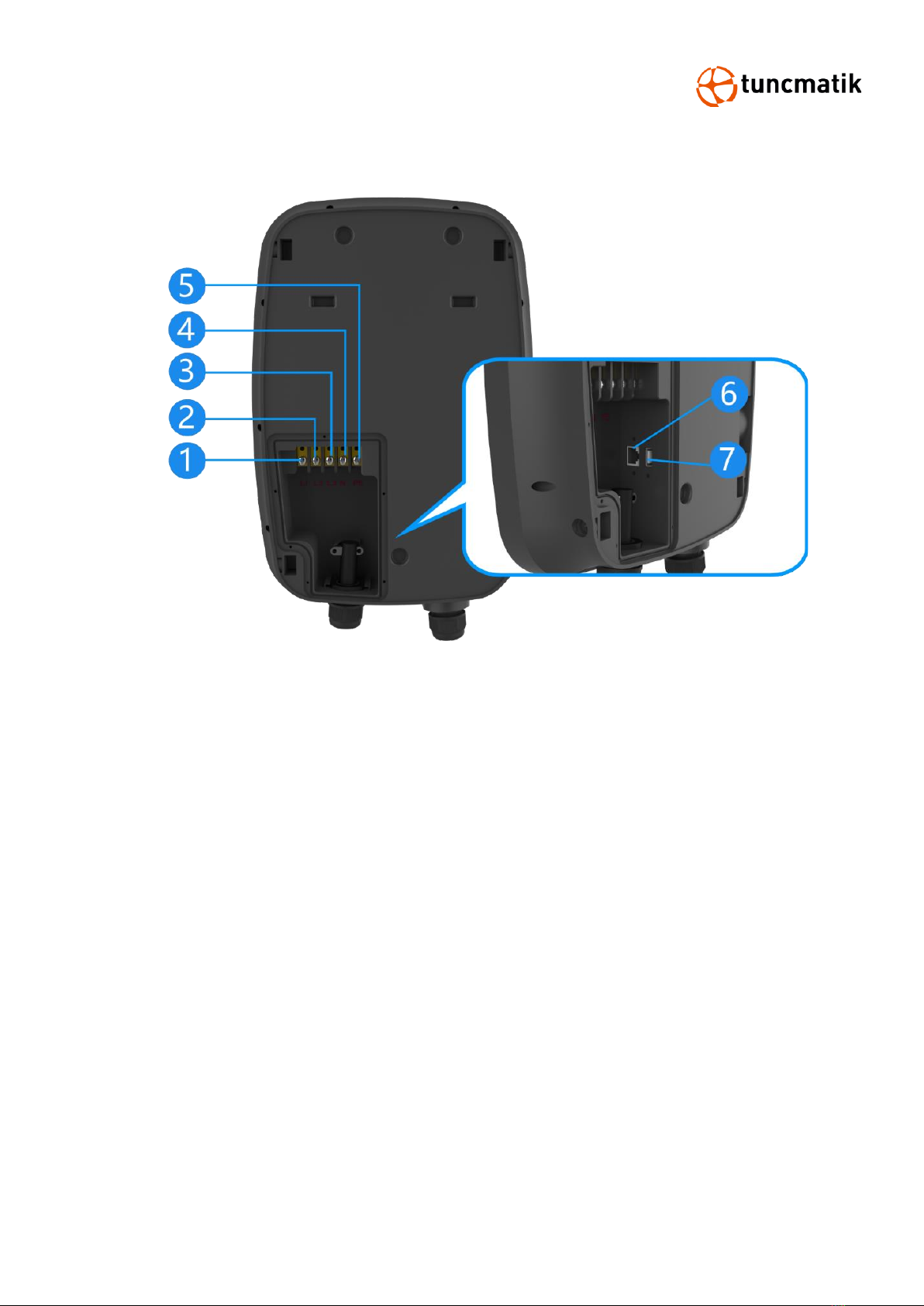
3.2. Back Description ............................................................................................. 6
4. Packaging ................................................................................................................ 7
5. Installation............................................................................................................... 8
5.1. Pre-Installation ............................................................................................... 8
5.2. Cable Reach ................................................................................................. 15
5.3. Construct
Foundation
................................................................................... 15
5.4. Dimensioned Drawing ................................................................................... 18
5.5. Space Requirement ....................................................................................... 19
5.6. Single Pedestal Installation ............................................................................ 20
5.7. Back-to-Back Pedestal Installation .................................................................. 26
5.8. Wall-Mount Charger Installation..................................................................... 27
6. Charging Process.................................................................................................... 29
6.1. Display and Usage ........................................................................................ 29
6.2. LED Operation .............................................................................................. 35
6.3. Precautions .................................................................................................. 36
6.4. EPO Operation .............................................................................................. 36
7. Routine Maintenance .............................................................................................. 37
8. Trouble Shooting .................................................................................................... 38

1
1. Safety Instructions
Read and follow the instructions and warnings in this Manual before attempting to install this
product. Keep this Manual for future reference.
Please follow the below safety precautions to prevent bodily injuries and property
damages.
Warning: When the product is running, it should pay attention to ventilation, heat
dissipation and keep the environment clean. Avoid installation in places with frequent
occurrence of storm, rainstorm, lightning and other severe weather.
Warning: During installation, if any abnormal phenomena such as cracking, loose
case lock, water leakage are showing up, all operations shall be stopped immediately
and professionals shall be informed in time to deal with them.
Warning: Do not put inflammable, explosive or combustible materials, chemicals,
combustible steam and other dangerous goods near the charge pile.
Warning: Please keep the charging plugs clean and dry. If there is any dirt, please
wipe it with a cleaning cadre. It is strictly prohibited to touch the charging core with
hands when it is powered.
Warning: It is strictly prohibited to use the charge pile when the charge plugs or
charging cable is defective, cracked, worn, and the charge plugs line is exposed. If
any, please contact the staff in time.
Warning: In case of rain and thunder, please use electricity carefully. It is better to
stop charging.
Warning: Do not attempt to disassemble, repair or modify the charging station. For
repairs or modifications, please contact the staff. Improper operation may result in
damage, water leakage, electricity leakage, etc.
Warning: It is forbidden to insert and unplug the plug during the charging process
to ensure the safety of life and the vehicle during the charging process.
Warning: It is strictly prohibited to continue to use this product for charging in case
of failure.
Warning: If any leakage or insulation failure occurs during the operation of the
product, please press the emergency power off button immediately.
Warning: Obvious maintenance marks shall be set up. Isolation and protection
measures shall be added to live parts that may be near by operators to avoid contact.

2
CAUTIONS
CAUTION: Wrong installation and testing of the charger will cause potential damage
to the vehicle battery, assembly, and the charger itself.
CAUTION: Do not operate the charger in temperatures outside its operating range
of -35°C to +55°C.
NOTE:
Electrical equipment should only be installed, operated, serviced, and maintained by qualified
personnel. No responsibility is assumed by our company for any consequences arising out of the
use of this material.
A qualified person is one who has skills and knowledge related to the construction, installation,
and operation of electrical equipment and has received safety training to recognize and avoid the
hazards involved.

3
2. Technical Specifications
Model
7KW
11KW
22KW
Charging Type
Charging Mode 3 Case C
Outlet Options
AC Type 2 (IEC 62196-2)
Input/ Output Current
rating
32A, single phase
16A, three phase
32A, three phase
Input/ Output Power
rating
Up to 7.4 kW
Up to 11 Kw
Up to 23 kW
Input/ Output voltage
220-240VAC
380-415VAC
380-415VAC
Input Frequency
50 Hz or 60 Hz
Number of EV Served
Up to 1
Cable Length
5.0 m, Optional: 7.5m
Distribution Systems
TT, TN , Split-phase
Connector Type
1P + N + PE
3P + N + PE
3P + N + PE
Protection
Overcurrent, overvoltage, undervoltage, ground fault, integrated
surge protection
Overvoltage Category
Type III
Energy Metering
Revenue grade energy meter
Cellular Communication
4G,
User in interface
Connectivity
Ethernet (RJ45)
User Authentication
QR code
User Interface
4.3" touchscreen LCD
Status Indication
3 indicators
Communication Protocols
Proprietary
Emergency Button
Yes
Configuration
Software Upgrade
Over-the-air (OTA)
Language System
English, Turkish
General characteristics
Protection Rating
IP65 and IK10 (cabinet) / IK08 (touchscreen)
Housing Material
Standard: PC
Operational Altitude
Up to 2000 m
Operating Temperature
-35 °C to +55 °C
Starage Temperature
-40 °C to +80 °C
Humidity
< 95%, non-condensing

4
Mounting
Wall-mount or pedestal stand (Cable can be wrapped around the
hanger) Stored shall be located at a height between 0.5m and 1.5 m
above ground level.
Dimensions (D x W x H)
mm
110 x 282 x 407
Net Weight (kgs)
7
Compliance Standards
Codes and Standards
IEC 61851-21-2, EN 61000-6-1, EN 61000-6-2, EN 61000-6-3, EN
61000-6-4,
EN 61000-3-2, EN 61000-3-3, EN 61000-3-11, EN 61000-3-12
Safety Standards
IEC/EN 61851-1, EN 62311, EN 62479, IEC 62423, IEC 61008-1,
IEC 61008-2-1
*Product specifications are subject to change without further notice

5
3. Introduction
The AC EV charger comes with a charging plug. The maximum output power of 23kw, with 99%
efficiency. For ease of operation, the electric car charger is equipped with a 4.3-inch industrial
touch screen, a standard Ethernet connection to communicate with LAN routers, vehicles, action
devices, and other chargers.
3.1. Product Overview
1. LED pilot lamp
2. Touch screen
3. Nozzle
4. EPO button
5. Upper part of the pedestal
6. Back plate of the pedestal
7. Middle baffle
8. Lower part of the pedestal
9. Back plate of the pedestal
10. Pedestals base

6
3.2. Back Description
1. Input terminal L1
2. Input terminal L2
3. Input terminal L3
4. Neutral terminal
5. Grounding terminal (PE)
6. RJ45 Ethernet port
7. USB port

7
4. Packaging
The charger is delivered in a carton packaging. The following figure shows the packaging for the
charger.
NOTE: The charger must be stored in its original packaging in a dry environment between -40 °C
to +80 °C.
It is recommended to ship the charger to its final destination in its original packaging and unpack
it there.

8
5. Installation
5.1. Pre-Installation
⚫Danger to life due to improper installation!
⚫Ignoring environmental conditions when handling electricity can lead to
hazardous situations.
Before performing any installation activities, carefully read each item listed in this chapter that is
critical to the installation process.
[Location Selection]
Consider before choosing where to install:
⚫Meets all criteria regarding charger placement and location.
⚫Accessible Design Standards.
⚫Make sure the installation location complies with cellular signal strength standards.
[Local Conditions]
⚫Area is dry and well ventilated.
⚫The area is not exposed to dust, high temperatures, explosive gases, flammable materials or
corrosive fumes.
⚫Wiring and conduit needed to connect the charger to the board.
⚫The location of the charging port when the vehicle is parked.
⚫Space clearance requires minimum dimensions for airflow and service channels.

9
[Input power distribution installation suggestions]
⚫Please configure CB (Circuit-breakers) and RCCB(Type B RCCB) before installation
The recommended specifications of Circuit-breakers and Type B RCCB are shown in
the following table:
Component
Manufacturer/
trademark
Type/
model
Value / rating
Standard
Circuit-breakers
with overcurrent
protection
Wenzhou Aoelec
Electrical Co., Ltd.
KBE
Ue= 415V~(3P+N);
50/60Hz, In=40A,
IEC/EN 60898-1
Type B RCCB
Wenzhou Aoelec
Electrical Co., Ltd.
R8B
Un= 415V~(3P+N);
50/60Hz, In=40A,
IΔn=30mA, Type B;
IEC 62423,IEC 61008-
1,IEC 61008-2-1
NOTE:
⚫The Type B RCCB test button shall be tested every month.
⚫The KBE and R8B are recommended for Circuit-breakers and Type B RCCB, respectively.
Warning: Before using this type of charging pile, Circuit-breakers and RCCB with similar

10
standard certification parameters must be configured, if you do not configure the Circuit-breakers
and RCCB that meet the certification parameters of similar standards, you will bear the
dangerous consequences!
⚫Before installing the charging station, you need to configure the wire box and then connect
the wires.
CAUTION: The screwdriver torque is 6KGF.
[Wired Network Settings]
1. Loosen the screws on the front cover of the charging station and open it on.
2. Dial the DIP switches 1-4 to OFF, and 5-8 to ON.

11
[WiFi Settings]
1. Loosen the screws on the front cover of the charging station and open it on.
2. Reset the DIP switch.
3. Connect the charging station to the power supply, then connect the WiFi module and the
laptop with a network cable.

12
4. Enter 192.168.16.254 in the browser, and a dialog box for entering the user name and
password will pop up. Both username and password are admin.
5. After logging in, select AP Client mode and set the parameters by picture.
⚫Network Mode:AP Client
⚫STA SSID: Please enter the WIFI name of the bridge router.
⚫STA Enctype:WPA2AES
⚫STA Password: Please enter the WIFI password of the bridged router.
⚫IP Type:DHCP
⚫AP Enable: Enable
⚫LAN IP Addr:192.168.16.254
⚫LAN Mask:255.255.255.0
⚫DHCP Server:Enable

13
6. After the parameters are set, click Apply to exit and unplug the network cable.
7. Dial the DIP switches 1-4 to ON, and 5-8 to the digital side.
8. Charging station is powered back on, DHCP needs to select Enable on the screen, and
then modify the billing model to backstage billing through the screen.
NOTE: Set DHCP first, and then set the billing model.

14
9. After waiting for about 40s, the IP address assigned by the WIFI module to the control
board will be automatically recognized: 192.168.16.100.
10. Install the front cover of the charging station.

15
5.2. Cable Reach
In the default configuration, the Charging station comes with a cable length of 500cm. Figure 5.1
below shows the Charging station's operating radius (5m).
Figure 5.1
5.3. Construct
Foundation
⚫
The Charger Pedestal can be built on a concrete foundation, the flat surface of the
foundation should not be less than the dimension of 400 mm * 400 mm.
⚫When preparing the foundation base and cabling pay regard to positions of cable through
holes and expansion bolts, which was dimensioned in Figures 5.2 & 5.3.

16
Figure 5.2 Construct Foundation for Pedestal Charger
Figure 5.3 Construct Foundation for Wall-Mount Charger
The height of the foundation is determined by the topography and natural environment
of the site. Depending on rainfall and drainage, a height of between 15 cm and 30 cm

17
above the ground is recommended. The foundation must be about 80 cm deep in the
ground due to frost protection.
NOTE:
⚫The unit must be mounted on solid and flat stone slabs or walls.
⚫Different types of slate require expansion bolts, or choose appropriate screws for
installation, and in some cases drill holes.
⚫The laying of power cables shall comply with relevant national and industry standards and
specifications.
⚫The cable selection specification should be selected according to the number of equipment
and the type, power, voltage and current level of the installed equipment.
⚫When laying the cable, it is strictly forbidden to expose it.
⚫When the cable is buried directly, the buried depth should not be less than 0.8m to
prevent freezing.
⚫The selection of power cable specifications should be selected according to the installation
environment and fire protection requirements.
Figure 5.4

18
5.4. Dimensioned Drawing
This manual suits for next models
5
Table of contents
Other Tuncmatik Batteries Charger manuals