Tuncmatik PRO DC CHARGER 60 kW User manual

info@tuncmatik.com / www.tuncmatik.com
User Manual
Tuncmatik Pro DC Charger
60 kW –80 kW –120 kW –
150 kW –180 kW
Electric Vehicle Charger
User Manual

Table of Contents
1. Safety Instructions............................................................................................ 1
2. Technical Specifications............................................................................................. 3
3. Introduction ............................................................................................................. 5
3.1. Brief introduction ............................................................................................ 5
3.2. Charging Socket head specification .................................................................. 6
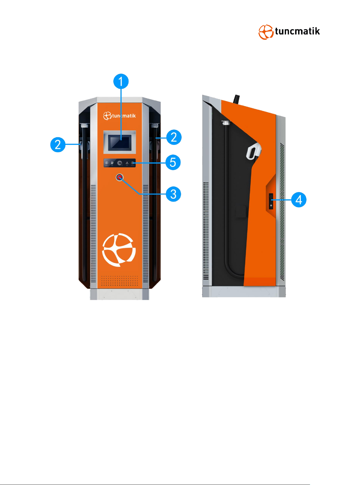
3.3. Product Overview............................................................................................ 7
4. Packaging & Transport .............................................................................................. 8
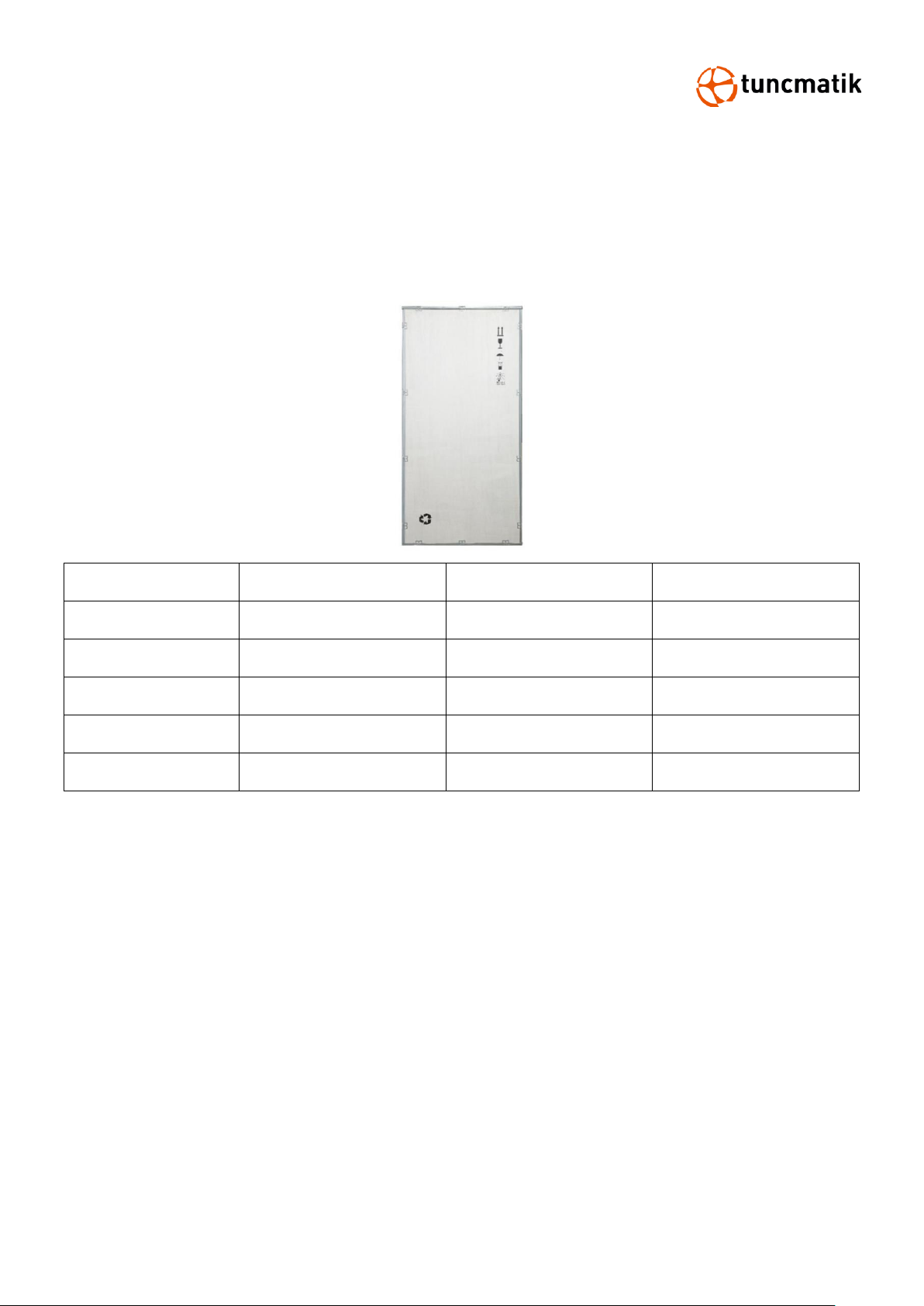
4.1. Packaging....................................................................................................... 8
4.2. Transport........................................................................................................ 9
5. Installation............................................................................................................. 10
5.1. Pre-Installation ......................................................................................... 10
5.2. Cable Reach ............................................................................................. 11
5.3.
Construct
Foundation
............................................................................... 12
5.4. Space Requirement ....................................................................................... 13
5.5. DC Charger Installation ............................................................................. 14
6. Charging Process.................................................................................................... 17
6.1. Charging Page Description............................................................................. 17
6.2. LED Operation .............................................................................................. 18
7. Charging Process.................................................................................................... 19
7.1 Charging Process (RFID CARD) ....................................................................... 19
7.2 Şarj süreci (QR CARD).................................................................................... 22
7.3. Charging Process (Account Adding)................................................................ 25
8. Device Settings............................................................................................. 28
8.1 LCD Password Settings ................................................................................... 28
8.3. Account Management.................................................................................... 29
8.4. Server Ethernet (LAN) Connection.................................................................. 30
8.5. SIM Card Installation..................................................................................... 32
9. Menu Function Descriptions .................................................................................... 37
10. Precautions .......................................................................................................... 38
11. EPO Operation...................................................................................................... 39
12. Routine Maintenance ............................................................................................ 40
13. Trouble Shooting .................................................................................................. 41
14. Fault Codes and Definations .................................................................................. 43

1
1. Safety Instructions
Read and follow the instructions and warnings in this Manual before attempting to install this
product. Keep this Manual for future reference.
Please follow the below safety precautions to prevent bodily injuries and property
damages.
Warning: When the product is running, it should pay attention to ventilation, heat
dissipation and keep the environment clean. Avoid installation in places with frequent
occurrence of storm, rainstorm, lightning and other severe weather.
Warning: During installation, if any abnormal phenomena such as cracking, loose
case lock, water leakage are showing up, all operations shall be stopped immediately
and professionals shall be informed in time to deal with them.
Warning: Do not put inflammable, explosive or combustible materials, chemicals,
combustible steam and other dangerous goods near the charge pile.
Warning: Please keep the charging plugs clean and dry. If there is any dirt, please
wipe it with a cleaning cadre. It is strictly prohibited to touch the charging core with
hands when it is powered.
Warning: It is strictly prohibited to use the charge pile when the charge plugs or
charging cable is defective, cracked, worn, and the charge plugs line is exposed. If
any, please contact the staff in time.
Warning: In case of rain and thunder, please use electricity carefully. It is better to
stop charging.
Warning: Do not attempt to disassemble, repair or modify the charging station. For
repairs or modifications, please contact the staff. Improper operation may result in
damage, water leakage, electricity leakage, etc.
Warning: It is forbidden to insert and unplug the plug during the charging process
to ensure the safety of life and the vehicle during the charging process.
Warning: It is strictly prohibited to continue to use this product for charging in case
of failure.
Warning: If any leakage or insulation failure occurs during the operation of the
product, please press the emergency power off button immediately.
Warning: Obvious maintenance marks shall be set up. Isolation and protection
measures shall be added to live parts that may be nearby operators to avoid contact.

2
CAUTIONS
CAUTION: Wrong installation and testing of the charger will cause potential damage
to the vehicle battery, assembly, and the charger itself.
CAUTION: Do not operate the charger in temperatures outside its operating range
of -35°C to +55°C.
NOTE:
Electrical equipment should only be installed, operated, serviced, and maintained by qualified
personnel. No responsibility is assumed by our company for any consequences arising out of the
use of this material.
A qualified person is one who has skills and knowledge related to the construction, installation,
and operation of electrical equipment and has received safety training to recognize and avoid the
hazards involved.

3
2. Technical Specifications
MODEL
PRO DC
CHARGER
60 kW
PRO DC
CHARGER
90 kW
PRO DC
CHARGER
120 kW
PRO DC
CHARGER
150 kW
PRO DC
CHARGER
180 kW
Charging Type
DC fast charging
Outlet Options
C: CCS2 cable, A: CCS1 cable, J:CHAdeMO cable
AC Input Power
93 A, 64
kVA @
400V 50 Hz
139 A, 96
kVA @
400V 50
Hz
185 A, 128
kVA @
400V 50Hz
224 A, 160
kVA @
400V 50Hz
278 A, 192
kVA @
400V 50Hz
Input Voltage Range
400 VAC or 380 VAC ± 10%
Input Frequency
50 Hz or 60 Hz
DC Output Power
Rating
60 kW
90 kW
120 kW
150 kW
180 kW
DC Output Voltage
200-1000 Vdc (Constant power from 300-1000 Vdc)
Number of EV Served
Up to 2 (CC, AA, JC, JJ) Up to 1 (C, A)
Cable Length
5 m default, optional 6.0 m/ 7.0 m
Maximum
Current
CCS Cables
200 A
200 A, Optional: 300A
CHAdeMO
Cables
125 A, Optional: 200 A
Electro-Magnetic
Compatibility
Class A (optional Class B) according to EN 61000-6-3:2007
Network Type
TN-S. TN-C, TN-C-S, TT (required external RCD)
Connector Type
3P + N + PE
Protection
Overcurrent, overvoltage, undervoltage, integrated surge
protection, grounding fault including DC leakage protection, door
opening protection
Overvoltage Category
Type II
Power Factor (Full Load)
≥ 0.99
THDi
≤ 5%
Efficiency
94% (peak)
95%
(peak)
Standby Power
< 35W
Short Circuit Current
10 kA
Pre-charge Current
< 1 A
Inrush Current
< 100 A
Leakage Current
0.8 mA
Energy Metering
Standard: Meter for DC outlet, Optional: AC inlet

4
Cellular Communication
GSM, 4G, LTE
USER INTERFACE
Connectivity
Internet access vi a 4G/3G/Ethernet (RJ45)
User Authentication
RFID, QR code
User Interface
7” LCD high-contrast touchscreen
Communication
Protocols
Proprietary and OCPP 1.6J
RFID Reader
ISO/IEC 14443 A/B Mifare RFID reader
Emergency Button
Yes
CONFIGURATION
Software Upgrade
Over-The-Air (OTA)
Language System
English, French, Spanish, Turkish, Russian
GENERAL CHARACTERISTICS
Protection Rating
IP54 and IK10 (cabinet) / IK08 (touchscreen)
Housing Material
SGCC, Optional: SUS430
Operating Altitude
Up to 2000m
Operating Temperature
-35 °C to 55 °C
Storage Temperature
-40 °C to 70 °C
Humidity
< 95%, non-condensing
Mounting
Free-standing cabinet
Dimensions (D x W x H)
mm
750 x 740 x 1830
Net Weight (kgs)
295
335
355
375
395
COMPLIANCE STANDARDS
Codes & Standards
IEC 61851-1 ed 3, IEC 61851-21-2 ed 1, IEC 61851-23 ed 1,
IEC 61851-24 ed 1
Communication to the
EV
DIN 70121, ISO/IEC 15118 ed 1, CHAdeMO 1.2
* Product specifications are subject to change without further notice

5
3. Introduction
3.1. Brief introduction
It takes only 30 minutes at most to fill a car to 95% capacity through the charging plug of
the DC electric vehicle charging station. Provide green energy solutions for smart cities.
The electric vehicle charger adopts intelligent power distribution system design to meet
different application requirements. The maximum power is 180kW, which is compatible with
different BMS systems. It is also equipped with CHAdeMO and CCS connectors to meet different
local regulations.
Matching application fields:
⚫Expressway charging service
⚫Parking lot
⚫Shopping center
⚫Commercial fleet
⚫Residential area
For ease of operation, the electric car charger is equipped with a 7-inch industrial touch
screen, a standard Ethernet connection and an embedded RFID reader with WI-FI features to
communicate with LAN routers, vehicles, action devices, and other chargers. (WIFI
communication is optional)

6
3.2. Charging Socket head specification
Figure 3.1 Charging plug, CHAdeMO and CCS structure
CHAdeMO
CCS

7
3.3. Product Overview
1. Touch screen
2. Charging Socket (cable)
3. Emergency stop button
4. Door lock
5. Operation indication panel (Socket insertion indication, card swiping indication, work
indication)

8
4. Packaging & Transport
4.1. Packaging
The Charging station is delivered in a specialized wood packaging. The following figure shows the
packaging, and size information for the Charging station.
Model Name
W [mm]
D [mm]
H [mm]
60kW
819
848
2000
90kW
819
848
2000
120kW
819
848
2000
150kW
819
848
2000
180kW
819
848
2000

9
4.2. Transport
Move the charging station to the required installation location with a forklift truck.
Please move the Charging station with the utmost caution!
NOTE: The Charger must be stored in its original packaging in a dry environment from
-40 °C to 70 °C.
It is recommended to transport the Charger to its final destination in its original packaging and
unpack it there.

10
5. Installation
5.1. Pre-Installation
⚫Danger to life due to improper installation!
⚫Ignoring environmental conditions when handling electricity can lead to
hazardous situations.
Before performing any installation activities, carefully read each item listed in this chapter that is
critical to the installation process.
[Location Selection]
Consider before choosing where to install:
⚫Meets all criteria regarding charger placement and location
⚫Accessible Design Standards
⚫Make sure the installation location complies with cellular signal strength standards
[Local Conditions]
⚫Area is dry and well ventilated
⚫The area is not exposed to dust, high temperatures, explosive gases, flammable materials or
corrosive fumes
⚫Wiring and conduit needed to connect the charger to the board
⚫The location of the charging port when the vehicle is parked
⚫Space clearance requires minimum dimensions for airflow and service channels.

11
5.2. Cable Reach
In default configuration, the Charging station comes with a cable length of 500cm. The figure5.1
below shows the operating radius (5m) of the Charging station.
Figure 5.1

12
5.3.
Construct
Foundation
⚫
The charging station can be built on a concrete foundation, the flat surface of foundation
should not be less than the dimension of 800 mm * 800 mm.
⚫When preparing the foundation base and cabling pay regard to positions of cable through
holes and expansion bolts
, which was dimensioned in Figure 5.2.
Figure 5.2
The height of the foundation is determined by the topography and natural environment
of the site. Depending on rainfall and drainage a height between 15 cm and 30 cm above
the ground is recommended. Because of frost-proof the foundation has to be about 80
cm deep under the ground.
NOTE:
⚫The unit must be mounted on solid and flat stone slabs.
⚫Different types of stone slabs require the use of expansion bolts, or choose suitable screw
installation, in some conditions require drilling.
⚫The laying of power cables shall be in accordance with relPRO DC CHARGERnt national and
industrial standards, specifications.
⚫Cable selection specification shall be selected according to the number of equipment and the
type, power, voltage and current level of the equipment installed.
⚫When cables are laid, they are strictly forbidden to be exposed.
⚫When the cable is buried directly, the buried depth should not be less than 0.8m in order to
prevent freezing.

13
⚫The selection of power cable specifications should be selected according to the installation
environment and fire requirements.
Figure 5.3
5.4. Space Requirement
When installing the charger, ensure a minimum distance from possible objects around the charger
to allow sufficient airflow,and secondly, to leave room for possible service or maintenance
operations.
The following figure shows the recommended minimum distance to be maintained during the site
installation:
Figure 5.4
NOTE: Clearance dimensions are published for airflow and service access only. Consult with the
local safety codes and standards for additional requirements in your local area.

14
5.5. DC Charger Installation
Step 1:Demolition of steel belt box and foam
⚫Demolition of steel belt box and foam; See Figure 5.5
Step 2:Remove the top four ring hole screws
⚫Remove the top four ring hole screws (M12); See Figure 5.6
Figure 5.5 Figure 5.6
Step 3:Fix the lifting ring on the screw hole
⚫Fix the lifting ring (M12) on the screw hole; See Figure 5.7
Step 4:Remove the fixing screws between the chassis and the base
⚫Open the front and back doors and remove the fixing screws (M12) between the chassis
and the base; See Figure 5.8

15
Figure 5.7 Figure 5.8
Step 5:Lift the charging station to the cement fixing platform
⚫Use the mounting plate and level tools to mark the mounting position in cement platform
⚫Close the front and back doors, and then lift the chassis to the cement fixing platform with
steel wire ropes through lifting rings; See Figure 5.9
Step 6:Attach the charging station to cement platform
⚫Open the front and back doors, connect the screws (M12) with the fixing holes of the
cement platform through the base. See Figure 5.10
Figure 5.9 Figure 5.10

16
Step 7:Connect the Charger
⚫Turn on the cover plate, See Figure 5.11
⚫Install the L1, L2, L3, N, PE wire. Position the connection according to the following figure.
See Figure 5.12
(Take 180kw as an example, the wiring mode of other models is the same as 180kw)
Figure 5.11 Figure 5.12
NOTE:
⚫Before charging the charging station, recheck all electrical connections after all wiring is
complete.
⚫After the charging station is powered on, the LCD screen will display the status of the
charging station.

17
6. Charging Process
6.1. Charging Page Description
Figure 6-1 Real-time charging interface
1. Charging time
2. Socket type
3. Charging voltage
4. Charging cost
5. Charging capacity
6. Charging current
7. Change charge type
8. Stop button
9. Network status
10. Charging capacity of charged vehicle
11. Language selection

18
6.2. LED Operation
The front panel of the charger has an operation indication area to display the charger status.
Figure 6.4 LED Front Panel
1. Insertion indicator power LED of charging gun head A
When hung on the charging plug A, the power LED (green) lights up.
When charging plug A is charged, the power LED (green) flashes.
2. Power LED
When the charger is powered on, the power LED (yellow) will light up.
When the charger is turned off, the power indicator will fade out.
3. When there is any fault or error in the charger, the fault LED (red) will light up.
At this point, for safety reasons, the charger will stop running.
4. Insert Gun Indicating Power LED of Charging Gun Head B
When hung on the charging plug B, the power LED (green) will light up.
When charging plug B is charged, the power LED (green) flashes.
5. NFC sensing area
To start or stop charging, please place the NFC card near this area.
This manual suits for next models
4
Table of contents
Other Tuncmatik Batteries Charger manuals