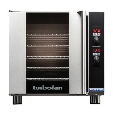
turbofan 30D Series User manual

Service Manual
G32D4/D5
(Digital Operation)
30D
SERIES
Amendment 10
11 May 2015

Amendment 10
11 May 2015
The reproduction or copying of any part of this manual by any means whatsoever is strictly forbidden unless authorized previously in writing
by the manufacturer.
In line with policy to continually develop and improve its products, Moffat Ltd. reserves the right to change the specifications and design
without prior notice.
© Copyright Moffat Ltd. May 2015.
MANUFACTURED BY
Moffat Limited
Rolleston 7675
New Zealand
INTERNATIONAL CONTACTS
AUSTRALIA
Moffat Pty Limited
Web: www.moffat.com.au
E.Mail: [email protected]
Main Office: (tel) +61 (03) 9518 3888
(fax) +61 (03) 9518 3833
Service: (tel): 1800 622 216
Spares: (tel): 1800 337 963
Customer Service: (tel): 1800 335 315
(fax): 1800 350 281
CANADA
Serve Canada
Web: www.servecanada.com
E.Mail: [email protected]
Sales: (tel): 800 551 8795 (Toll Free)
Service: (tel): 800 263 1455 (Toll Free)
NEW ZEALAND
Moffat Limited
Web: www.moffat.co.nz
E.Mail: [email protected]
Main Office: (tel): 0800 663328
UNITED KINGDOM
Blue Seal
Web: www.blue-seal.co.uk
E.Mail: [email protected]
Sales: (tel): +44 121 327 5575
(fax): +44 121 327 9711
Spares: (tel): +44 121 322 6640
(fax): +44 121 327 9201
Service: (tel): +44 121 322 6644
(fax): +44 121 327 6257
UNITED STATES
Moffat
Web: www.moffat.com
Sales: (tel): 800 551 8795 (Toll Free)
(tel): +1 336 661 1556
Service:
(fax): +1 336 661 9546
(tel): 866 673 7937 (Toll Free)
(tel): +1 336 661 1556
(fax): +1 336 661 1660
REST OF WORLD
Moffat Limited
Web: www.moffat.co.nz
E.Mail: [email protected]

Contents List
Amendment 10
11 May 2015
G32 Turbofan Convection Oven.
Model Numbers Covered in this Manual
G32D4 - Turbofan Oven - 4 Tray Convection Oven.
G32D5 - Turbofan Oven - 5 Tray Convection Oven.
Specifications ........................................................................................................................... 2
Installation ............................................................................................................................... 4
Installation Requirements
Unpacking
Location
Clearances
Stand Mounted Ovens
Electrical Connection
Gas Connection
Recommended Water Specifications
Water Connection
Positioning and Levelling of Oven
Stand Mounted Ovens
Initial Start-Up
Commissioning
Operation.................................................................................................................................. 7
Oven Control Panel (Up to Ser. No. 762119)
Oven Control Panel (From Ser. No. 762120)
Changing Operator Settings
Operator Settings
Parts Replacement ................................................................................................................. 10
5.1 Parts Replacement
5.2 Adjustment and Calibration
Controller Programming ........................................................................................................ 22
6.1 Viewing / Changing Service Parameters
6.2 Viewing / Changing Service Parameters (Up to Ser No. 762119)
6.3 Viewing / Changing Service Parameters (From Ser No. 762120)
Electrical Schematics ............................................................................................................. 26
Wiring Diagrams..................................................................................................................... 27
Exploded Parts Lists............................................................................................................... 29
Accessories ............................................................................................................................ 36
Gas Conversion and Specifications ........................................................................................ 37
Appendix 1 - Oven Door Reversal........................................................................................... 39
ALL INSTALLATION AND SERVICE REPAIR WORK MUST BE CARRIED OUT BY QUALIFIED PERSONS ONLY.
IMPROPER INSTALLATION, ALTERATION, ADJUSTMENT, MAINTENANCE OR SERVICE MAY CAUSE PROPERTY
DAMAGE, INJURY OR DEATH.
ENSURE ELECTRIC AND GAS SUPPLIES ARE TURNED OFF BEFORE SERVICING.
ALWAYS TEST AFTER SERVICE REPAIRS
WARNING:

2
1 Specifications
Amendment 10
11 May 2015
G32D4/D5

3
Specifications 1
Amendment 10
11 May 2015
Oven Gas Supply Requirements and Specifications
G32D5 (110 - 120V):
G32D4 (240V) - UK Only:
Category: II2H3P.
Flue Type: A1.
G32D4 (220 - 240V) - All Other Markets:
Natural Gas LP Gas
Input Rating 35 MJ/hr. 35 MJ/hr.
1.75 kPa. 2.75 kPa.
Operating Pressure 1.05 kPa. 2.75 kPa.
Gas Connection ½” NPT.
Electrical Power Ratings 1 Phase, 110-120V, 60HZ, 220W.
Oven Tray Details Tray Capacity 5 x US Full Pan.
Tray Spacing 85mm / 31/3”.
Water Connection ¾” BSP with ¾” GHT Adaptor supplied (80 psi / 550 kPa
maximum pressure).
Supply Pressure
Natural Gas Propane
Input Rating 10 kW 10 kW
Supply Pressure 20 mbar 30 - 37 mbar
Operating Pressure 10 mbar 25 mbar
Gas Connection ½” BSP Male.
Electrical Power Ratings 220-240V, 1P+N+E, 50/60HZ, 200W.
Oven Tray Details
Tray Capacity 4, 18” x 26” / 460 x 660 Full Size Sheet Pan Capacity.
4, 600 x 400 Tray Capacity.
Tray Spacing 110mm.
Water Connection ¾” BSP (80 psi / 550 kPa maximum pressure).
Natural Gas LP Gas (Propane)
Input Rating 35 MJ/hr. 35 MJ/hr.
Supply Pressure 1.13 - 3.4 kPa. 2.75 - 5.0 kPa.
Operating Pressure 0.75 kPa. 2.35 kPa.
Gas Connection ½” BSP Male.
Electrical Power Ratings 220-240V, 1P+N+E, 50/60HZ, 200W.
Oven Tray Details Tray Capacity 4 x US Full Pan / EN 600 x 400.
Tray Spacing 110mm.
Water Connection ¾” BSP (80 psi / 550 kPa maximum pressure).

4
2 Installation
Amendment 10
11 May 2015
Installation Requirements
This installation of this appliance must conform with local codes, or in the absence of local codes, must conform to the National Codes shown
below covering gas and electrical safety.
Australia: - AS5601 - Gas Installations.
New Zealand: - NZS5261 - Gas Installation.
Australia / New Zealand: - AS/NZS3000 - Wiring Rules.
United Kingdom: - Gas Safety (Installation & Use) Regulations 1998.
- BS6173 - Installation of Catering Appliances.
- BS5440 1 & 2 - Installation Flueing & Ventilation.
- BS7671 - Requirements for Electrical Installations.
Ireland: - IS 820 - Non - Domestic Gas Installations.
Important:
Installation shall comply with local gas, electrical and health and safety requirements.
It is most important that this oven is installed correctly and that oven operation is correct before use.
If you have any questions regarding the proper installation and / or operation of this oven, please contact your local
Turbofan distributor.
Technical Data Plate - Location
Installation
Installations must be carried out by authorised persons only.
Failure to install equipment to the relevant codes and
manufacturers specifications shown above, will void the warranty.
This oven must be electrically earthed / grounded in accordance
with local codes.
Installation must allow for a sufficient flow of fresh air for the
combustion air supply. Combustion air requirements:
Natural Gas 10m³/hr.
LPG 9m³/hr.
Components having adjustments protected (e.g. paint sealed) by
manufacturer are only to be adjusted by an authorised service
agent. They are not to be adjusted by the installation person.
Unpacking
1. Remove all packaging and transit protection including all
protective plastic coating from the exterior stainless steel
panels.
2. Check the oven and supplied parts for damage. Report any
damage immediately to the carrier and distributor.
3. Check that the following parts have been supplied with your
oven:-
4 x Leg Adjustable.
Adaptor Brass.
Rubber Washer.
4. Report any deficiencies to the distributor who supplied your
oven.
5. Securely fit the 4 legs supplied with the oven.
6. Check that the available gas and electrical supply is correct to
that shown on the Technical Data Plate located on the front
right hand side panel.
Refer to ‘Specifications’ section, ‘Oven
Specifications Tables’.
USA / Canada Only)

5
Installation 2
Amendment 10
11 May 2015
Location
1. This oven must be installed in an area of adequate air supply.
Adequate ventilation is essential, to prevent dangerous build
up of combustion products. DO NOT obstruct the air flow
around the ventilation slots.
2. This oven must be fitted on supplied legs in all installations.
(When installed on a manufacturers stand, the legs are used
to locate the oven in the correct position.
3. All air for burner combustion is supplied from beneath the
appliance. Legs must always be fitted and no obstructions
placed beneath or around the base of the appliance, as
obstructions will cause incorrect operation and / or failure of
the appliance.
4. Installation must allow for a sufficient flow of fresh air for the
combustion air supply.
5. The area around the appliance must be kept free and clear
from combustibles.
6. Position the oven in its approximate working position.
It should be positioned so that the control panel and oven
shelves are easily reachable for loading and unloading.
7. Use a spirit level to ensure oven is level from side to side and
front to back. (If this is not carried out, uneven cooking could
occur).
Clearances
1. To ensure correct ventilation for the motor and controller, the
following minimum installation clearances are to be adhered
to:
CLEARANCE FROM SOURCE OF HEAT.
A minimum distance of 300mm (12”) from appliance sides
is required.
NOTE: Fixed installations require at least 500mm clearance
at the right hand side of oven for service access.
Oven Vent
Important:
The vent located on the top of the oven must NOT be
obstructed.
Electrical Connection
Each oven should be connected to an adequately protected power
supply and an isolation switch mounted adjacent to, but not
behind the oven and must be readily accessible to the operator.
This switch must be clearly marked and readily accessible in case
of fire.
Check the electricity supply is correct to as shown on the
Technical Data Plate on the front right hand corner of the oven
side panel.
Ensure that the oven is fitted with the appropriate power cord and
plug.
Gas Connection
A ½" BSP or ½" N.P.T connection is provided at the bottom rear
of the oven.
A restraint chain anchor has been provided below the gas
connection point on the appliance, for fitment of a restraint chain.
It is important that adequately sized piping run directly to the
connection joint on the oven with as few tees and elbows as
possible to give maximum supply volume.
A suitable jointing compound which resists the break down action
of LPG must be used on every gas connection.
Check all gas connections for leakages using soapy water or other
gas detecting equipment.
Check the technical data plate located on the front right hand
corner of the oven, for correct operating pressure and gas orifice
size for the gas being used, before operation.
The appliance combination gas valve is fitted with an internal
regulator for adjusting the operating pressure. To access, remove
appropriately marked service panel from beneath the oven door.
Unscrew and remove regulator cap from the gas valve. Adjust the
regulator to achieve the stated pressure. Also refer to the
‘Specifications’ section.
NOTE: The Pressure Test Point is located behind the front
service panel beneath the oven door.
This oven must be earthed / grounded.
Warning
Do not use a naked flame to check for gas leakages.
Warning
Regulator
Cap
Pressure Test
Point
Combustible
Surface
Non Combustible
Surface
Left / Right
Hand Side 75mm/3” 75mm/3”
Rear 75mm/3” 75mm/3”
Top 600mm/24” 200mm/8”

6
2 Installation
Amendment 10
11 May 2015
Water Connection - Optional
NOTE: If the Moisture Mode cooking option is not required,
the oven does not need to be connected to a water
supply.
1. Tighten 2 screws securing water
connection to rear of oven. (These
have purposely been left loose to
prevent damage to the water
connection during transit).
2. Connect a cold water supply to the
water inlet (R ¾” Connector) on the
oven.
- Max Inlet Pressure 80psi / 550kPa.
3. Turn ‘On’ the water supply and check for leaks.
Recommended Water Specifications
In order to prevent corrosion or scaling in the oven and water
system due to supplying water that is either too soft or too hard,
the following recommendations should be used as a guideline.
Hardness: Between 60 and 90ppm.
PH: Greater than 7.5.
Chlorides: Less than 30 ppm.
Positioning and Levelling of Oven
1. Correctly locate the oven into its final operating position and
using a spirit level, adjust the oven feet so that the oven is
level and at the correct height.
Stand Mounted Ovens
For ovens that are to be mounted to a stand, the oven legs are
used to level the oven on the stand. Refer to the
instructions supplied with separately ordered stands for mounting
details.
Initial Start-Up
Before using the new oven;
1. For first time use of the oven, operate the oven for about 1
hour at 200°C/ 400°F to remove any fumes or odours which
may be present.
2. Please refer to the Operation Section of this manual for details
on how to correctly operate and shutdown the oven.
Commissioning
Before leaving the new installation;
Check the oven functions in accordance with the operating
instructions specified in the ‘Operation’ section of this manual.
Lighting the oven.
Turning ‘Off’ the oven.
Ensure that the operator has been instructed in the areas of
correct lighting, operation, and shutdown procedure for the
appliance.
NOTE: If for some reason it is not possible to get the
appliance to operate correctly, shut off the gas
supply and contact the supplier of this appliance.
Tighten Screws.

7
Operation 3
Amendment 10
11 May 2015
Operation Guide
Temperature Display - Shows
the preset chamber temperature.
When used with ‘Temperature’ button,
shows actual oven temperature for 5
seconds.
Shows Cooking Modes and Error Codes.
Steam Button and LED -
Activates the ‘Steam Mode’.
Temperature Adjustment Control.
Time Display - Shows cook
time in full minutes only from
180 - 1, and seconds for final
minute only.
On / Off / Stand-By Button and
LED - Press ‘On / Off’ button once
to turn the oven ‘On’.
Press and hold ‘On / Off’ button for
2 seconds to turn the oven ‘Off’.
Time Adjustment Control.
Programming Button and LED - Used
to enter the ‘Programming’ mode.
Temperature Button and LED - Shows
actual oven temperature for 5 seconds on
the Temperature Display.
LED ‘On’ when heating; LED flashes when
showing actual temperature.
Light On / Off Button and LED - Turns
oven light ‘On / Off’.
Start / Stop Button and LED - Pressing
the ‘Start / Stop’ button for 2 seconds,
when in the cooking cycle, will end the
cooking cycle.
Oven Control Panel (Up to Ser. No. 762119)

8
3 Operation
Amendment 10
11 May 2015
Temperature Display -
Shows pre-set chamber temperature.
When used with the ‘Temp’ key, display shows
actual oven temperature for 5 seconds.
Shows cooking programs and error codes.
‘Steam’ Key and LED -
Used to set automated steam level or to
provide a manual steam injection when
in Manual Steam Mode.
LED is ‘On’ when automatic moisture injection is
set or when steam is manually injected.
Temperature Adjustment Control
Time Display -
Shows cook time in full minutes only
from 180 - 10, and in minutes and seconds for
the final 10 minutes.
NOTE:
In Core Temp Mode, time display alternates
between ‘CP’ and set core probe temperature.
‘On/Off’ Key and LED -
A dual-function key:
Press ‘On/Off’ key once to turn oven ‘On’.
Press and hold ‘On/Off’ key for
1.5 seconds to turn the oven ‘Off’.
Time Adjustment Control
NOTE: In Core Temp Mode, ‘Timer’ knob is
used to set core probe temperature.
‘Program’ Key and LED -
Used to select cooking programs, and to
set program parameters.
‘Temp’ Key and LED -
Displays actual oven temperature for
5 seconds on Temperature Display. LED
‘On’ when heating element is on
(heating indicator).
LED flashes when Upper Display is showing
actual temperature.
NOTE:
In Core Temp Mode, this key is used to
display Actual Oven Temperature (Upper
Display) and Core Probe Temperature (Lower
Display).
‘Light’ Key and LED -
Switches oven lights ‘On/Off’. LED is
‘On’ when oven lights are ‘On’.
‘Timer-Start/Stop’ Key & LED -
The ‘Timer-Start/Stop’ key is used to
control the following functions:-
Cancelling Alarm (All Modes).
Starting Core Temp Mode (Core Temp
Mode).
Starting Timer (Manual Mode).
Re-setting Timer (Manual Mode).
Starting Program (Program Mode).
Cancelling and Re-setting Program
(Program Mode).
Core Probe Connection Point
Oven Control Panel (From Ser. No. 762120)

9
Operation 3
Amendment 10
11 May 2015
Changing Operator Settings
With the Oven in ‘Stand-By’ Mode (i.e. Power to oven but both displays blank).
1. ENTER OPERATOR PARAMETER MODE.
Press and hold 'Steam' and ‘Timer-Start/Stop’ keys together.
‘Upper’ Display will show ‘PAS’.
‘Lower’ Display will flash ‘000’.
2. SETTING PASSWORD (Operator Password - 123).
Rotate ‘Timer Control’ to set password.
(123 - Operator Password)
Press ‘Light’ key to confirm password.
‘Upper Display’ will show one of the Parameter Codes, eg.
‘Lower Display’ will show the parameter value.
3. SETTING THE PARAMETERS.
Rotate ‘Timer’ knob to the parameter required.
Press ‘Light’ key to confirm parameter required. ‘Lower Display’ will flash.
While ‘Lower Display’ is flashing, rotate ‘Timer’ knob to select value required.
Press ‘Light’ key to confirm value. ‘Lower Display’ will stop flashing.
4. EXITING THE PARAMETER MODE.
Press ‘On/Off’ key, to return to Stand-By Mode.
Operator Settings
Setting
Number
Description
Default
Setting
Oven Pre-Heat; - (Automatic Pre-Heat Temp on oven start-up). 150ºC
302ºF
Light Auto ‘Off’ Setting Time -
0 = ‘On/Off’.
1 = 1 minute auto ‘Off’.
2 = 2 minutes auto ‘Off’, etc.
0
Alarm Volume - Can be adjusted to suit operators preference. 5
Program Pre-Heating Condition - This setting allows for pre-heating ‘Ready’ temperature in
‘Program Mode’ Mode to be set higher than Program Set Temperature. Factory Default Setting
is ‘0’ (Equal to Program Setting).
0
Multi-Stage Enable (From Ser. No. 762120 only).- This setting enables multi-stage
programming. Factory Default Setting is ‘YES’, multi-stage programming is enabled.
Changing this setting to ‘no’ simplifies programming and program cooking.
YES
Setting
Range
60 - 260°C
140 - 500°F.
0 - 60 mins.
0 - 10.
0 - 30°C
0 - 54°F.
‘YES’ or ‘no’.

10
5 Parts Replacement
Amendment 10
11 May 2015
5.1 Replacement
5.1.1 Oven Controller /
Encoder.............................................................................................................................................11
5.1.2 Cooling
Fan /
Transformer /
Capacitor ..........................................................................................................................................12
5.1.3 Overtemp Thermostat /
Temperature
Probe...........................................................................................................................13
5.1.4 Oven Lamp Assy ...............................................................................................................................14
5.1.5 Oven Fan /
Fan Motor .........................................................................................................................................15
5.1.6 Ignition Module /
Burner Overtemp (Thermal Switch) .................................................................................................16
5.1.7 Door Microswitch /
Microswitch Return Spring ...............................................................................................................16
5.1.8 Gas Valve /
Gas Burner /
Ignition Electrode Assembly.............................................................................................................17
5.1.9 Door Inner Glass /
Door /
Door
Hinges......................................................................................................................................18
5.1.10 Water Solenoid .................................................................................................................................19
5.2 Adjustment & Calibration
5.2.1 Door Alignment ................................................................................................................................20
5.2.2 Door Catch / Latch Adjustment........................................................................................................20
5.2.3 Door
Microswitch..............................................................................................................................21
5.2.4 Temperature Calibration .................................................................................................................. 21

11
Parts Replacement 5
Amendment 10
11 May 2015
5.1.1 Oven Controller /
Encoder
To remove the Digital Control Board:-
1. Remove screw on underside of control panel.
2. Lift panel up to unhook at top.
3. Disconnect plugs from rear of control panel.
Note position of connectors before disconnecting plugs
from control board.
4. Disconnect earth connection at rear of control panel.
5. Undo the shake-proof securing nuts (8).
6. Remove digital control board from rear of control panel.
To replace the Digital Control Board:-
1. Ensure 8 spacers are fitted to threaded studs on rear of control
board before fitting new board.
2. Fit replacement digital control board to threaded studs and
secure with nuts supplied and tighten nuts hand tight.
3. Re-connect plugs to control board, noting position of
connectors when re-fitting.
5.1 Replacement
Control Panel Screw
Securing Nuts (8)
To Program the New Oven Controller
1. Check / adjust Parameters P01, P02 and P24 to the model
specific values shown below.
Encoder
1. With control panel removed from the oven, remove control
knob from control panel.
2. Disconnect encoder plug from digital control board.
3. Remove oven controller if necessary.
4. Remove encoder from control panel by removing 2 securing
screws.
Securing
Screws
Model /
Revision Key Identifiers PO1 PO2 P24
G32D
Rev 01
No Light Key.
Fan LO Key. °C / °F
as reqd. N/A
G32D
Rev 03
Square Lights in Oven.
Keys - New style graphics °C / °F
as reqd. N/A

12
5 Parts Replacement
Amendment 10
11 May 2015
5.1.2 Cooling Fan / Transformer / Capacitor
1. Remove 2 screws on lower corners of side panel.
2. Pull bottom of panel out and away from bottom of oven.
3. Pull down on panel to remove side panel.
Cooling Fan
1. Remove 2 screws securing cooling fan bracket.
2. Rotate LH side inwards to remove fan assembly. Remove
cooling fan from bracket.
3. Replace in reverse order.
Transformer
1. Disconnect electrical connections from transformer.
2. Remove 2 screws securing transformer to oven chassis.
Transformer Specifications;
Primary; 200 - 208V / 220 - 240V.
Primary; 110 - 120V.
Secondary;
12Vac.
3. Replace transformer and refit in reverse order.
Capacitor
1. Remove wires from rear of capacitor.
2. Remove capacitor securing nut.
3. Replace capacitor(s) and refit in reverse order.
Capacitor Specifications;
Motor Capacitor, 3uF (208 - 240V).
Motor Capacitor, 12uF (110-120V).
Securing Screws
Securing Screws
Cooling Fan
Transformer
Capacitor
Securing Screws
Securing Nut
Capacitor
Transformer

13
Parts Replacement 5
Amendment 10
11 May 2015
5.1.3 Overtemp Thermostat /
Temperature Probe
1. Remove RH louvered side panel.
2. Inside oven remove side oven rack.
Overtemp Thermostat
1. From inside the oven, remove overtemp phial holder (two
screws).
2. Withdraw phial through oven cavity.
3. Remove wires from overtemp thermostat, noting positions.
4. Remove mounting nut securing overtemp to mounting bracket
and remove the overtemp.
5. When replacing the overtemp use RTV silicone sealant to seal
the hole in the oven liner.
6. Refit overtemp in reverse order.
Overtemp Phial Holder
Securing Screws
Seal hole with
RTV Silicone
Temperature
Probe
Temperature Probe
Securing Screws
Mounting Nut
Temperature
Probe
1. Remove
control panel.
2. Disconnect temperature probe cable from controller.
3. From inside oven, remove RH side oven rack.
4. Undo temperature probe securing screw(s).
5. Withdraw probe and cable through oven cavity.
6. Clean off any existing silicone from around the temperature
probe opening in the oven inner wall.
7. Fit the new gasket to the rear of the new temperature probe
and feed the probe cable through oven cavity.
8. Connect temperature probe cable to oven controller.
9. Secure temperature probe to oven using the supplied screws.
10. Refit the control panel.
11. Carry out a functional check of temperature probe using the
oven controller.
Temperature Probe Type PT1000
Temperature oC (oF) Resistance ± 5%
0 (30) 1000 Ω
50 (122) 1194 Ω
100 (212) 1385 Ω
150 (302) 1573 Ω
180 (356) 1685 Ω

14
5 Parts Replacement
Amendment 10
11 May 2015
5.1.4 Oven Lamp Assy
Oven Lamps (Up to Ser. No. 762119)
1. Remove the oven rack and LH side rack from oven.
2. Unscrew and remove the lamp glass (anti-clockwise) from the
oven.
3. Remove the light bulb which is a push fit into the light holder
and replace if required.
4. Remove seal fitted between lamp glass and holder and replace
if required.
5. Remove the LH Oven side
panel.
6. Disconnect the electrical
connections to the oven lamp
assy being replaced.
7. Pull back the insulation to
reveal the rear of the lamp
assembly.
8. Depress the 3 spring
loaded locking tabs on the
rear of the light assy and
push the assembly into the
oven and remove.
9. Refit oven light assy in
reverse order.
10. Ensure the insulation is
re-positioned around the rear
of the lamp assembly.
11. Refit the LH side rack and
oven rack to the oven.
12. Refit the LH oven side panel.
Disconnect
Securing Tabs (3)
Oven Lamps (From Ser. No. 762120)
Oven Lamp / Oven Lamp Glass / Oven Lamp Seal /
Oven Lamp Housing
1. Remove LH side rack from oven.
2. Remove 4 screws securing the lamp support frame.
3. Remove support frame, glass lens and gasket.
4. Remove light bulb if required (this is a push fit into housing).
To replace Oven Lamp Housing:
1. Remove oven non louvered side panel.
2. Pull back insulation to reveal rear of lamp assy.
3. Disconnect electrical connections on rear of lamp assy.
4. Depress spring loaded locking tabs on rear of light assembly
and push assembly into oven and remove.
5. Refit oven lamp assembly in reverse order.
Screws
Depress Spring
Tabs
Disconnect Electrical
Connections (3)

15
Parts Replacement 5
Amendment 10
11 May 2015
5.1.5 Oven Fan / Fan Motor
1. Remove RH louvered side panel.
Oven Fan
1. Inside oven remove RH Side oven rack.
2. Remove the 2.5mm grub screw securing the oven fan to the
fan motor shaft.
3. Remove the oven fan from inside the oven.
NOTE: Ensure the E-Clip is still fitted to the motor shaft
before replacing the oven fan.
3. Refit oven fan, pushing fan back against the E-Clip.
4. Rotate the fan until the fan securing grub screw is located
over the flat of the motor shaft.
5. Securely tighten the grub screw onto the ‘D’ section of the
motor shaft to secure the fan to motor shaft.
2.5mm Grub Screw
E-Clip
Motor Shaft
Fan Motor
1. Remove the oven fan as shown opposite.
2. Remove and retain the E-Clip fitted to the motor shaft.
3. Disconnect motor wires from motor connection block, note
wire positions.
4. Remove Motor mounting screws and remove the motor from
the oven.
5. Replace motor and secure with 4 screws.
6. Reconnect motor wires to connection block, note wire
positions.
7. From inside the oven refit the E-Clip into the groove on the
motor shaft.
8. Refit oven fan as shown opposite.
9. Refit RH oven side panel.
Screws
E-Clip
Motor Shaft
Remove and Retain E-Clip
Motor Shaft
Grub Screw Note Flat on Motor Shaft
for Grub Screw location.
Fan

16
5 Parts Replacement
Amendment 10
11 May 2015
5.1.6 Ignition Module /
Burner Overtemp (Thermal Switch)
1. Remove RH louvered side panel.
Ignition Module
1. Disconnect plug connections from Ignition Module.
2. Remove and replace Ignition Module.
3. Re-connect the plug connections to the Ignition Module.
Burner Overtemp (Thermal Switch)
1. Remove RH side panel.
2. Remove wires from burner overtemp.
3. Remove securing screws and replace burner overtemp.
4. Refit replacement burner overtemp and connect up wires to
overtemp.
5. Refit RH side and Gas Control panels.
Ignition Module
Securing Screws
Screws
Burner Overtemp
5.1.7 Door Microswitch /
Microswitch Return Spring.
To replace Door Microswitch:
1. Remove
control panel.
2. Remove oven RH side panel.
3. Remove electrical connections from door microswitch.
4. Remove
microswitch.
5. Check adjustment when new door microswitch is fitted. Refer
Section 5.2. ‘Adjustment & Calibration’.
To replace Door Microswitch Return Spring:
1. Remove
control panel.
2. Unscrew and remove spring securing screw and spacer from
microswitch bracket.
3. Unclip and remove return spring from microswitch rod and
microswitch bracket.
4. Refit replacement spring in reverse order.
Door Microswitch
Screw
Spring
Spacer
Retaining
Clip
Microswitch Rod
Microswitch

17
Parts Replacement 5
Amendment 10
11 May 2015
5.1.8 Gas Valve / Ignition Electrode
Assembly / Gas Burner
1. Remove gas control panel.
Gas Valve & Burner Injector
1. Remove gas control panel.
2. Remove cover bracket, 1 screw.
3. Remove earth and power connectors.
4. Disconnect gas inlet pipe to Gas Valve.
5. Remove injector and securing nut.
6. Remove securing screws and remove gas valve with bracket.
7. Replace and refit in reverse order.
8. Remove screw cap and fit correct spring for the gas type being
used.
9. Adjust operating pressure as shown in Section 9. ‘Gas
Conversion and Specifications’ section.
Screw
Injector & Nut
Gas Inlet Pipe
Earth Connector
Power
Connector
Burner Bracket
Screws
Screw Cap
Ignition Electrode Assembly
1. Remove burner access panel.
2. Disconnect wires from the Ignition Electrode Assembly to the
Ignition Module.
3. Remove 2 slotted screws securing Ignition Electrode Assembly
to the oven.
4. Withdraw the ignition electrode assembly and replace.
5. Before fitting the new ignition electrode assembly, check the
spark electrode / flame sensor gaps are as shown in Section
5.2 ‘Adjustment and Calibration’.
6. Re-connect wires from the new Ignition Electrode Assembly to
the Ignition Module.
Gas Burner
1. Remove Ignition Electrode Assembly as shown above.
2. Remove burner bracket screws (2).
3. Carefully withdraw burner.
4. Fit replacement burner and refit in reverse order.
Screws

18
5 Parts Replacement
Amendment 10
11 May 2015
5.1.9 Door Inner Glass / Door / Door Hinges
To replace Door Inner Glass:
1. Undo inner glass retaining clip.
2. Lift inner glass up and pull bottom outwards to free bottom
pivot.
NOTE: Pivot spacer is a loose fit over pivot and may fall
out.
3. Lower inner glass to free top pivot and remove glass.
4. Replace and refit door inner glass in reverse order, remember
to refit Pivot Spacer to bottom hinge.
To replace Door:
1. Remove door inner glass (as above).
2. Whilst supporting door, unscrew and remove top door hinge
pivot bolt from the door top hinge assembly.
3. Remove the Nord-Lock Washer.
4. Lift door off the bottom hinge.
5. Refit door in reverse order.
Remove Door Top Pivot Bolt.
Pivot Spacer
Retaining Clip
To replace Door Hinges:
1. Remove door and inner glass complete. (as shown previous).
2. Remove 2 Hinge Plate Screws.
3. Remove the upper and lower hinge plates.
4. Refit replacement door hinge plates.
5. Refit door and inner glass.
NOTE: The Door Hinge Assembly can be ordered as a
complete Door Hinge Replacement Kit or as
separate items as shown below.
To replace Door Hinge Pivot Bushes:
1. Remove door complete.
2. Unscrew and remove top and bottom plates from the door.
3. Tap out the old Door Hinge Pivot Bushes and discard.
4. Gently Tap in the new pivot bushes.
5. Refit the oven door as shown opposite.
Remove Top or Bottom
Hinge Plate Screws.
Door Hinge Pivot Bush.
Nord-Lock Washer.
Door Hinge Pivot Pin.
Door Bottom Hinge Assemby.
Door Top Hinge Assemby.
Door Hinge Pivot Bush.
Nord-Lock Washer.
Door Hinge Pivot Pin.
Nord-Lock Washer.
Pivot Bush
Unscrew 2 Screws
Door Hinge Pivot Bush.
Other manuals for 30D Series
4
This manual suits for next models
2
Table of contents
Other turbofan Commercial Food Equipment manuals
Popular Commercial Food Equipment manuals by other brands

Diamond
Diamond PIZZAFORM DP45-EK Instructions for installation, use and maintenance

Amitek
Amitek AK654TN Installation, operating and service instructions

Blanco
Blanco INMOTION BW-UK 10 operating instructions

Borg & Overstrom
Borg & Overstrom U2 user guide

Oscartielle
Oscartielle Castor Wood instruction manual

BERJAYA
BERJAYA KM 3H Service manual