manuals.online logo
Brands
  1. Home
  2. •
  3. Brands
  4. •
  5. Turbovex
  6. •
  7. Industrial Equipment
  8. •
  9. Turbovex TX 3100A User manual

Turbovex TX 3100A User manual

Other manuals for TX 3100A

1

Other Turbovex Industrial Equipment manuals

Turbovex TX 3100A Installation and operating instructions

Turbovex

Turbovex TX 3100A Installation and operating instructions

Popular Industrial Equipment manuals by other brands

ABB +Q957 user manual

ABB

ABB +Q957 user manual

G.B.C BASIC EDGE 50 instruction manual

G.B.C

G.B.C BASIC EDGE 50 instruction manual

Tronair Batpak 11-6602-1000 Operation & service manual

Tronair

Tronair Batpak 11-6602-1000 Operation & service manual

Pilz PNOZ mi2p Operation manual

Pilz

Pilz PNOZ mi2p Operation manual

Clemco Zero BNP 6012 manual

Clemco

Clemco Zero BNP 6012 manual

Erskine Attachments V-Plow Operator's manual

Erskine Attachments

Erskine Attachments V-Plow Operator's manual

ABB HT610965 Operation manual

ABB

ABB HT610965 Operation manual

Morra MH 540 user manual

Morra

Morra MH 540 user manual

Eaton S090ST manual

Eaton

Eaton S090ST manual

GRIGGIO G 240 P4 instructions

GRIGGIO

GRIGGIO G 240 P4 instructions

Nexen AIR CHAMP HT45 user manual

Nexen

Nexen AIR CHAMP HT45 user manual

WTE V5 installation manual

WTE

WTE V5 installation manual

ABB HT845232 Operation manual

ABB

ABB HT845232 Operation manual

SMC Networks CJP Series Operation manual

SMC Networks

SMC Networks CJP Series Operation manual

JohnDow Industries JDI-AFT58 Operator's manual

JohnDow Industries

JohnDow Industries JDI-AFT58 Operator's manual

IMB MB9016A instruction manual

IMB

IMB MB9016A instruction manual

Clarke CUMB1 Assembly & operating instructions

Clarke

Clarke CUMB1 Assembly & operating instructions

amiad Arkal Spin Klin 2 user guide

amiad

amiad Arkal Spin Klin 2 user guide

manuals.online logo
manuals.online logoBrands
  • About & Mission
  • Contact us
  • Privacy Policy
  • Terms and Conditions

Copyright 2025 Manuals.Online. All Rights Reserved.

Turbovex A/S
Industrivej 45, DK –9600 Aars
Telefon: +45 96 98 14 62
e-mail: info@turbovex.dk –www.turbovex.dk
User manual and installation guide
TX 3100A
Rev. 2023.06.23
Side 2 af 33
Turbovex A/S
Industrivej 45, DK –9600 Aars
Telefon: +45 96 98 14 62
e-mail: info@turbovex.dk –www.turbovex.dk
Contents
1.0 General information.....................................................................................................3
1.1 Foreword....................................................................................................................3
1.2 Field of application .....................................................................................................3
1.3 Scope of delivery........................................................................................................3
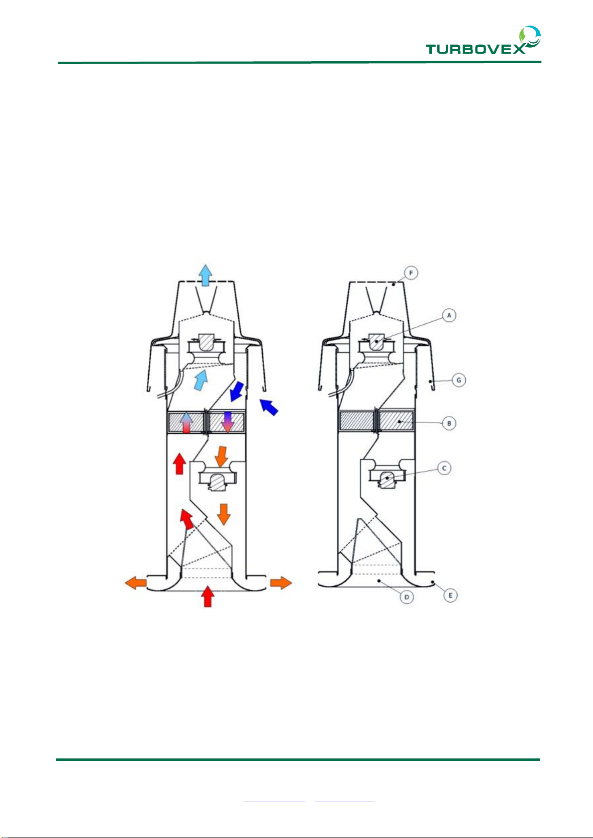
1.4 Function of the unit.....................................................................................................4
2.0 Installation....................................................................................................................5
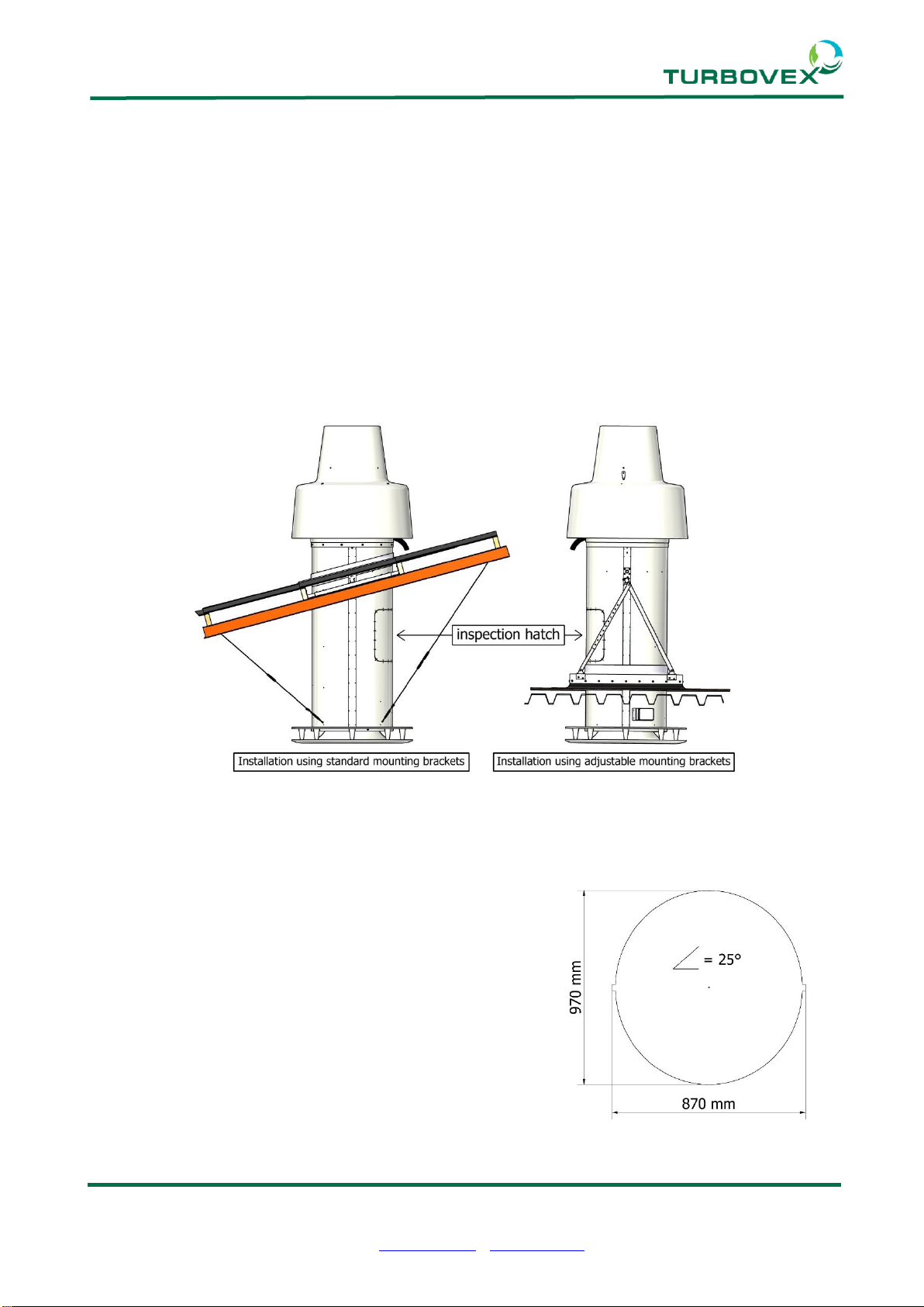
2.1 Dimensions ................................................................................................................5
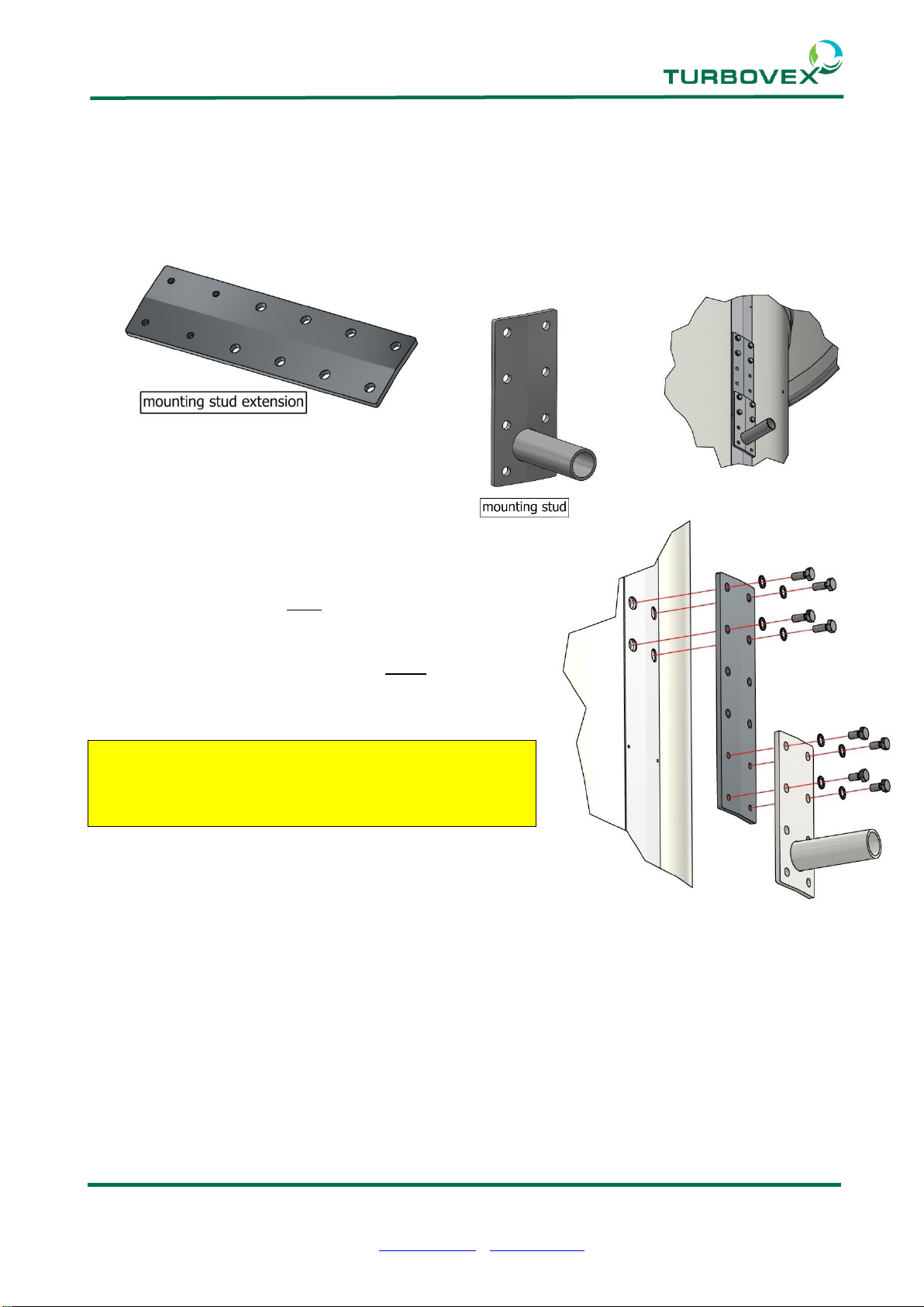
2.2 Mounting stud extensions...........................................................................................6
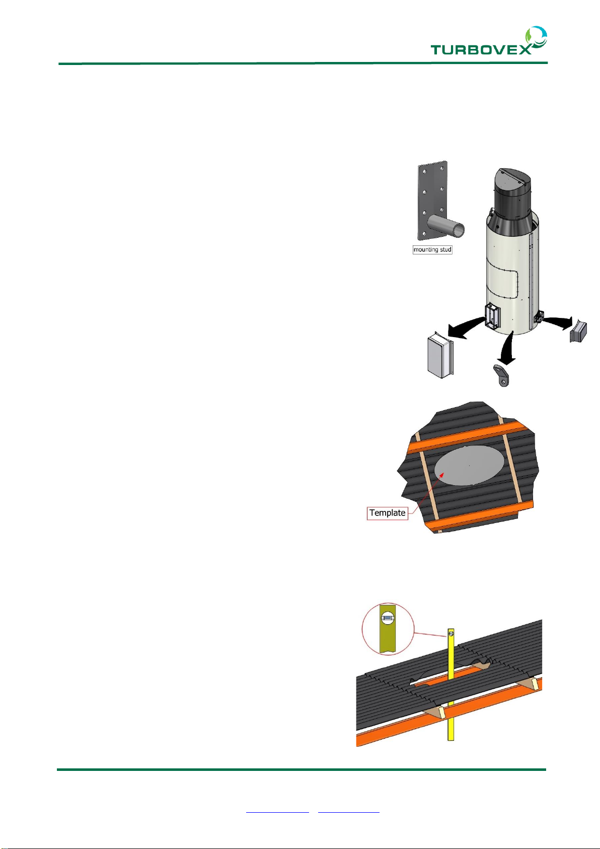
2.3 Placement..................................................................................................................7
2.4 Template....................................................................................................................7
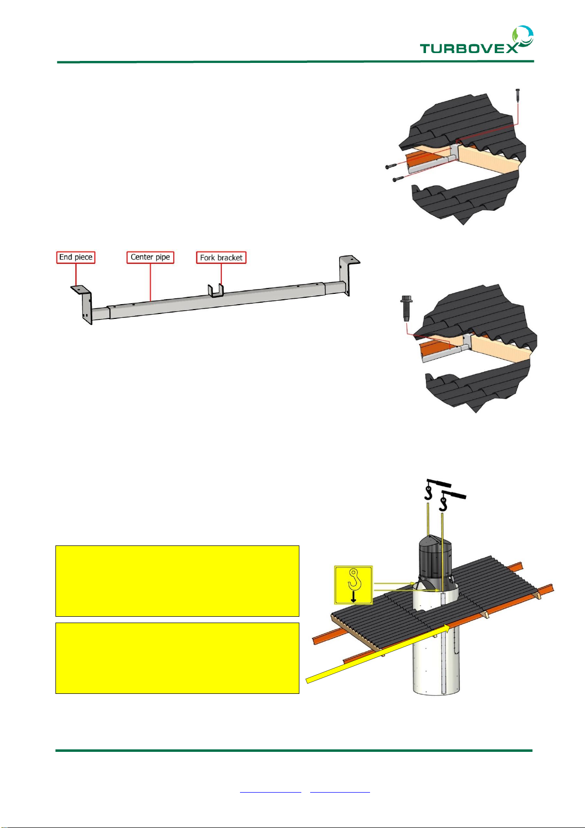
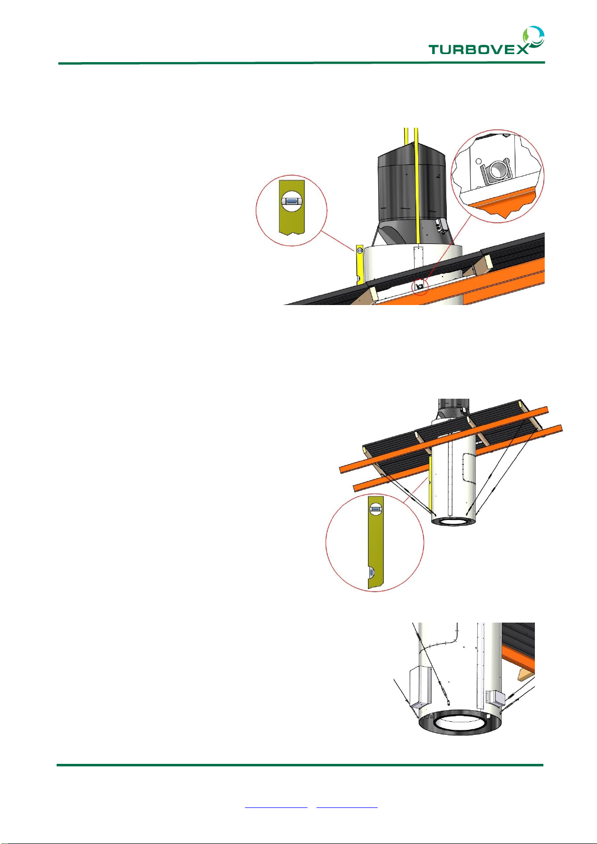
2.5 Installing the unit(standard mounting brackets)..........................................................8
2.6 Installing the unit(adjustable mounting brackets) .....................................................14
2.7 Installation of bottom extension................................................................................20
2.8 Installation of top extension......................................................................................22
2.9 Thermal insulation against condensation and loss of energy...................................23
3.0 Technical specifications ...........................................................................................24
3.1 Unit...........................................................................................................................24
4.0 Electrical wiring diagrams ........................................................................................25
5.0 Service........................................................................................................................29
5.1 Maintenance inspections..........................................................................................29
5.2 Service Checklist......................................................................................................30
5.3 Filter change ............................................................................................................31
6.0 Declaration of conformity .........................................................................................33
Side 3 af 33
Turbovex A/S
Industrivej 45, DK –9600 Aars
Telefon: +45 96 98 14 62
e-mail: info@turbovex.dk –www.turbovex.dk
1.0 General information
1.1 Foreword
This user´s manual contains technical information regarding the installation and
maintenance of a TX 3100A decentralized ventilation unit.
1.2 Field of application
Turbovex TX 3100A is designed for providing decentralized comfort ventilation in larger
rooms such as industrial premises, auto workshops and indoor sports arenas and similar
environments.
1.3 Scope of delivery
Turbovex TX 3100A is by default delivered with the main components listed below.
1. TX 3100A unit
2. Top cone
3. Filter holder
4. Inlet ring
5. Standard mounting brackets
In addition the unit is delivered with various screws and bolts, silicone rubber grout, wires
and wire tensioners.
Following can be purchased as option:
6. TX Electronic Control
The scope of delivery may change when other options for installation is purchased.
Side 4 af 33
Turbovex A/S
Industrivej 45, DK –9600 Aars
Telefon: +45 96 98 14 62
e-mail: info@turbovex.dk –www.turbovex.dk
1.4 Function of the unit
The principle of heat recovery in the TX3100A is based on the rotating heat exchanger (B).
The exhaust fan (A) draws the warm room air through the funnel of the inlet ring(D),
through half of the heat exchanger (B), and send it through the exhaust cap (F).
Simultaneously the inlet fan will (C) draws air through the inlet cap(G), sending it through
the other half of the heat exchanger. The heated fresh air is sent through the inlet ring (E)
and distributed evenly in the room.
One half of the rotating heat exchanger will always be in the hot airflow from the exhaust
air. When the heated material in the heat exchanger is in the cool flow of the inlet air, it will
transfer heat from the material to the fresh supply air.
The process is regenerative as the heat exchanger rotates at a constant low speed.
Side 5 af 33
Turbovex A/S
Industrivej 45, DK –9600 Aars
Telefon: +45 96 98 14 62
e-mail: info@turbovex.dk –www.turbovex.dk
2.0 Installation
2.1 Dimensions
Side 6 af 33
Turbovex A/S
Industrivej 45, DK –9600 Aars
Telefon: +45 96 98 14 62
e-mail: info@turbovex.dk –www.turbovex.dk
2.2 Mounting stud extensions
If further adjustment to the placement up or down of the unit is required, it is possible to
install mounting stud extensions with the mounting studs. With the mounting stud
extensions the placement can be adjusted additional 300 mm vertically.
The mounting stud extensions are attached to the
TX3100A unit using the long M8 bolts and washers
with which the mounting studs were attached by
default. The mounting studs are attached to the
mounting stud extensions using the short M8 bolts and
washers that comes with the mounting stud
extensions.
The mounting studs are attached to the mounting
stud extensions using the short M8 bolts and
washers through the threaded holes on the
mounting stud extensions.
Side 7 af 33
Turbovex A/S
Industrivej 45, DK –9600 Aars
Telefon: +45 96 98 14 62
e-mail: info@turbovex.dk –www.turbovex.dk
2.3 Placement
TX 3100A is intended for installation through the roof. The unit can be placed in roofs with
inclines ranging from 0 to 45 degrees. TX3100A is available with two types of mounting
brackets;
Standard mounting brackets place the unit with the inspection hatch inside the building
while adjustable mounting brackets place the unit with the inspection hatch outside the
building.
2.4 Template
It is recommended to create a template from the chart below based on incline of the roof.
The illustration is shown with an incline of 25°
0° = Ø 870 mm
5° = 870 x 880 mm
10° = 870 x 890 mm
15° = 870 x 900 mm
20° = 870 x 930 mm
25° = 870 x 970 mm
30° = 870 x 1010 mm
35° = 870 x 1070 mm
40° = 870 x 1140 mm
45° = 870 x 1240 mm
Side 8 af 33
Turbovex A/S
Industrivej 45, DK –9600 Aars
Telefon: +45 96 98 14 62
e-mail: info@turbovex.dk –www.turbovex.dk
2.5 Installing the unit(standard mounting brackets)
If the unit is installed by hoisting it up through the roof, the following components must be
temporarily removed for installing the unit:
•the 2 mounting studs
If the unit is to be installed by lowering it down through the roof,
the following components must be temporarily removed for
installing the unit:
•The 2 electrical boxes. The electrical wires that are
connected to the boxes are long enough, so that they don’t
need to be disconnected while installing the unit.
•The 4 wire brackets
The placement of the unit can be adjusted vertically through the
placement of the mounting studs as shown in 2.1 Dimensions and
2.2 Mounting stud extensions.
The placement and center of the unit is marked through
the roof. It is recommended using a template based on
the chart in 2.4 Template for this.
A hole is then drilled or cut vertically through the roof.
Side 9 af 33
Turbovex A/S
Industrivej 45, DK –9600 Aars
Telefon: +45 96 98 14 62
e-mail: info@turbovex.dk –www.turbovex.dk
According to the placement of the unit it is measured where
the two standard mounting brackets should be installed with
a distance between them of 1000 mm, so that the unit is
placed equally distanced from both.
The standard mounting brackets are designed for a distance
between the purlins of up to 1070 mm. The end pieces are
fastened to the purlins using the 12 included Ø8 mm wood
screws.
The center pipes are adjusted so that the fork brackets are
horizontally aligned and so that their co-centric line is in the
center of the hole. The center pipes are fixed in place through
the endpieces with the 8 Ø6,3 mm self-drilling screws.
The unit is hoisted in place with a crane.
If the 2 mounting studs were temporarily removed for installing,
they are now re-attached to the unit.
When choosing installation with standard
mounting brackets the unit must be placed
with the service hatch facing towards the
ridge of the roof.
If the 2 electrical boxes has been detached
for installing the unit, pay attention to them so
that they are not stuck and damaged during
the use of a crane with the unit.
Side 10 af 33
Turbovex A/S
Industrivej 45, DK –9600 Aars
Telefon: +45 96 98 14 62
e-mail: info@turbovex.dk –www.turbovex.dk
The unit is hoisted or lowered in place so that the mounting studs fall into place in the fork
shaped brackets of the standard mounting brackets. It is checked that the unit is plumb.
If the 4 wire brackets were temporarily removed for installing the unit, they are now re-
attached to the unit.
The remaining included 4 wire brackets are attached to the purlins or battens.
The included wires and wire tensioners are now attached between the 4 wire brackets on
the unit and the 4 wire brackets on purlins or battens. The wire tensioners are tightened so
that the unit is fixed and plumb.
With the unit and wires installed, fixed and adjusted the 2
electrical boxes can be re-attached to the unit.