Turtle Tough ULTRA Series User manual

TURTLE
TOUGH
®
turtletoughsensors.com
MANUAL
SMART DIGITAL SUSPENDED SOLIDS SENSOR
TSS

Turtle Tough: Total Suspend Solids Sensor Manual
Chapter 1. Introduction 2 Revised: 7 October 2022
Chapter 1. Introduction
1.1 | Product Overview
The digital Total Suspended Solids (TSS) is a used to detect the presence of suspended solid particles
in a fluid. The sensor utilises infrared scattered light technology to measure the intensity of scattered
light in a solution. The value of scattered light is proportional to the number of suspended solids within
the solution. The product is widely used in the monitoring of suspended solids/sludge concentration
in sewage plants, waterworks, water stations, surface water, aquaculture, industry, and other fields.
The sensor can come with an automatic cleaning brush to wipe away debris during operation.
1.2 | Product Specifications
Specification
Value
Unit
Measurement Range
(Customisable)
Standard Range:0.01 - 50,000
Low Range: 0.01 - 20,000
High Range: 0.01 - 120,000
mg/L
Dual Beam Measurement
Accuracy
±5% of Measured Reading or ±10mg/L. Whichever is
greater.
Single Beam Measurement
Accuracy
±10% of Measured Reading or ±10mg/L. Whichever is
greater.
Repeatability
±3%
Resolution
0.1 or 1, Depending on measurement range
mg/L
Pressure Range
≤ 0.2
MPa
Main Material
Body: SUS316L
Cover: PPS+ Glass Fibre
Cable: PUR
Power Supply
9~36
VDC
Communication Protocol
Modbus RS485
Modbus Baud Rate
19200
Modbus Data Bits
8
Modbus Parity
Even
Modbus Stop Bit
1
Storage Temperature
-15~50
℃
Measuring Temperature
0-45 (Non-Freezing)
℃
Weight
0.8
Kg
Protective Rate
IP68 / NEMA6P
Cable Length
Standard: 10m.
Maximum: 100m

Turtle Tough: Total Suspend Solids Sensor Manual
Chapter 1. Introduction 3 Revised: 7 October 2022
1.3 | Product Dimensions
SUS316L/Titanium alloy external dimension
Figure 1: Dimensional Diagram of TSS Sensor

Turtle Tough: Total Suspend Solids Sensor Manual
Chapter 1. Introduction 4 Revised: 7 October 2022
1.4 | Sensor Installation Example Methods
Figure 2: Quick-Dismantling Pool-side Installation of TSS Sensor

Turtle Tough: Total Suspend Solids Sensor Manual
Chapter 1. Introduction 5 Revised: 7 October 2022
Figure 3: Classic Pool-side Installation of TSS Sensor

Turtle Tough: Total Suspend Solids Sensor Manual
Chapter 1. Introduction 6 Revised: 7 October 2022
Figure 2: Railing Installation of TSS Sensor

Turtle Tough: Total Suspend Solids Sensor Manual
Chapter 2. Digital Operation 7 Revised: 7 October 2022
Chapter 2. Digital Operation
2.1 | Sensor Connection
The Turbidity sensor should be connected using the following terminations:
#
1
2
3
4
5
Cable Colour Red/Brown Black Blue White
Yellow +
Green
Signal +12VDC AGND RS485 + RS485 - GND
2.2 | Modbus Communication Settings
By default, this sensor has the following Modbus communication settings. These settings can be
modified by writing values to their respective holding registers on the sensor. See the Modbus register
table for more information.
MODBUS-RTU Default Settings
Baud-Rate
19,200
Data-Bits
8
Parity
Even
Stop Bit
1
Node Address
10
2.3 | Reading and Writing Values
Note: The turbidity sensor stores values in its registers as either a 16-bit integer or an in the IEEE754
32-bit floating point format. In applications such as Modbus Poll, a readable number can be gathered
from the Modbus registers by changing the format to “Little-Endian Byte Swapped” or “Float CDAB”.
In software terms, this means when reading a value, two registers must be combined in the order
Register 2; Register 1 such that it creates a single 32-bit value. This value must then be converted to
binary and read as an IEEE745.
Register #
Hexadecimal
Binary
Register 1
40 20
0100 0000 0010 0000
Register 2
23 45
0010 0011 0100 0101
Combined
23 45 40 20
0010 0011 0100 0101 0100 0000 0010 0000
IEEE754 Float
1.06929703959e-17
Any Modbus software must be designed to be able to handle the complexities of converting a set of
two registers into IEEE754 format. The method for converting from a 32-bit binary number to a 32-bit
float can be found here: http://mathcenter.oxford.emory.edu/site/cs170/ieee754/.

Turtle Tough: Total Suspend Solids Sensor Manual
Chapter 2. Digital Operation 8 Revised: 7 October 2022
2.3.1 | Reading Values Using Modbus Poll:
The third-party program “Modbus Poll” can be used to
diagnose and set up the sensor. It is the simplest
method of communication to the Turbidity Sensor and
shall be used in this document for demonstration
purposes. To begin, connect the sensor to a PC using a
Turtle Tough Windows Interface Box. Once connected
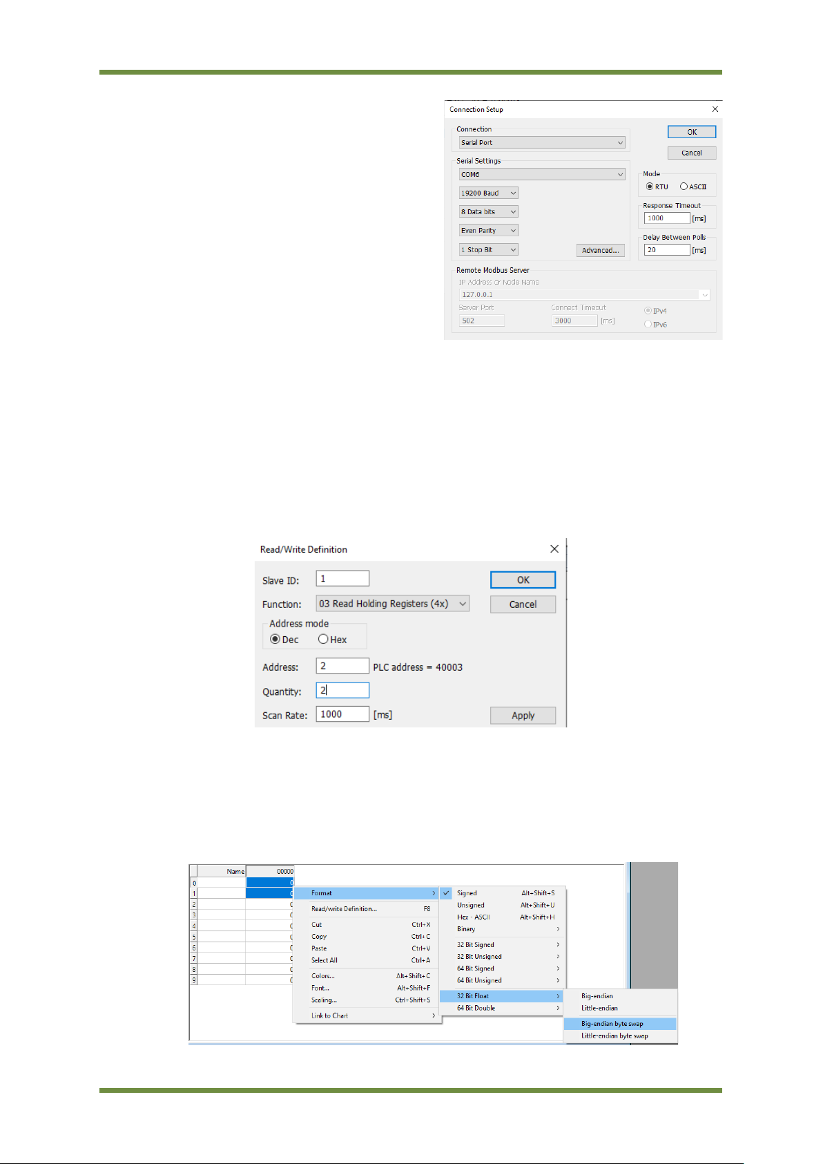
open Modbus Poll and connect to the sensor using the
following settings: 19200 Baud Rate, 8 Data Bits, Even
Parity and 1 Stop Bits. Ensure the correct COM port is
selected.
2.3.2 | Reading the TSS value using Modbus Poll:
1) In the menu at the top of the application, select “Setup” then “Read/Write Definitions”.
2) In the menu set the following parameters:
•Slave Address = 1 (or whatever the slave address of your sensor is).
•Function = “03 Read Holding Registers”.
•Address = 2
•Quantity = 2.
3) This will read the first two holding registers on the sensor. These holding registers contain a
32-bit floating point representation of the TSS value stored in the IEEE754 format (see above).
To convert the IEEE754 to a single floating-point number, select the two registers then right-
click them and navigate to Format -> 32 Bit Float -> Little-endian byte swap. This will combine
the two registers and display the TSS value.

Turtle Tough: Total Suspend Solids Sensor Manual
Chapter 2. Digital Operation 9 Revised: 7 October 2022
2.3.3 | Writing a 16-bit integer using Modbus Poll
1) In Modbus Poll, press the “06” button in the header menu.
2) In the menu enter the following parameters:
•Slave ID: 1 (or the node address of your sensor)
•Address: The address you are changing (See
Modbus Table Below)
•Value: The Value you are changing the register to.
•Use Function: “16: Write Multiple Registers”
3) Press “Send”
2.3.4 | Writing an IEEE754 32-bit float using Modbus Poll.
4) In Modbus Poll, press the “16” button in the header menu.
5) In the menu enter the following parameters:
•Slave ID: 1 (or the node address of your sensor)
•Address: The address you are changing (See Modbus Table Below)
•Quantity:2
•Type:“Float Little-Endian byte swap”
3) In the box on the right double click the register displayed.
4) Enter the floating-point value that you want the register to have then press “OK”.
5) Press “Send”.

Turtle Tough: Total Suspend Solids Sensor Manual
Chapter 2. Digital Operation 10 Revised: 7 October 2022
2.4 | Modbus Register Table
Register
Name
Address
Read /
Write
Data
Type
Range
Unit
Description
TSS Value 2 Read IEEE754 0~50000 NTU
Stores the currently read
TSS value.
Brushing
Time 11 Read 16-Bit
Integer
15/ 30/ 60/ 240/ 720/
1440/ 4320/
10080
Minutes
The amount of time
between automatic
brushing of the lens.
Parameter 13 Read
16-Bit
Integer
1 or 2 Seconds
1 is Turbidity, 2 is TSS. This
value should always be 2/
Probe
Humidity 14 Read 16-Bit
Integer 1
Should be less than 10 (10
Indicates the sensor has
been flooded)
Baud Rate 16
Read
&
Write
16-Bit
Integer
0 = 4800
1 = 9600
2 = 19200
3 = 38400
Baud Rate of the sensor.
Should be 2 by default.
Node Address 17
Read
&
Write
16-Bit
Integer 1
The Modbus node address
of the sensor. By default,
will be 1.
Serial No. 1 18 Read
16-Bit
Integer
-
First 4 numbers of the
serial number
Serial No. 2 19 Read
16-Bit
Integer
-
Middle 4 numbers of the
serial number
Manual
Brushing
Order
20 Write 16-Bit
Integer 66
Send 66 to manually
activate the sensor
cleaning brush.
Automatic
Brushing
Time
21
Read
&
Write
16-Bit
Integer
15/ 30/ 60/ 240/ 720/
1440/ 4320/
10080
Minutes
Use this register to write
the amount of time
between automatic
brushings.
Calibration
Factor Calibration
TSS Factor 6
Read
&
Write
IEEE754 0.1 ~ 10 Send: Standard Solution
Value / Read Value
Two/Four Point Calibration
Calibration
Mode 27
Read
&
Write
16-Bit
Integer
2: 2 Point Calibration
3: Four-Point Calibration
Send 2 to enter 2-point
calibration mode.
Send 3 to enter 3-point
calibration mode.
Set
Calibration
Point
28
Read
&
Write
16-Bit
Integer
1: First Point
2: Second Point
3: Third Point
4: Fourth Point
Send to signify the sensor
is ready to calibrate the
given point
Set Standard
Solution
Value
20
Read
&
Write
IEEE754 0-50000 TSS Send Target Value
Set Actual
Solution
Value
22
Read
&
Write
IEEE754 0-50000 TSS Send Actual Value

Turtle Tough: Total Suspend Solids Sensor Manual
Chapter 3. Calibration 11 Revised: 7 October 2022
Chapter 3. Calibration
Notes:
1. Ensure that the probe lens is 15cm away from the bottom of the container during
calibration.
2. Ensure that there are no air bubbles at the front end of the lens during calibration.
3. When correcting, it is recommended that the calibration cup be protected from light.
3.1 | Factor Calibration
The TSS sensor has been calibrated at the factory. If a self-calibration is needed, it can be carried out
using either factor or multi-point calibration modes. Factor calibration is a simple way to calibrate the
sensor by multiplying the non-engineered sensor reading by a coefficient “factor” to create a more
accurate engineered value.
If there is a large deviation between the measured value and a standard value, the slope of the
calibration curve can be corrected using factor calibration using the following method:
1) Connect the sensor to a PC and set up Modbus Poll (as explained above)
2) Slowly immerse the sensor into the TSS standard solution
3) Calculate the correction factor using the formula:
=
4) Write the calculated factor to address 6 & 7 using the IEEE754 method (as shown above):

Turtle Tough: Total Suspend Solids Sensor Manual
Chapter 3. Calibration 12 Revised: 7 October 2022
3.2 | Multi-Point Calibration
In situations where increased levels of accuracy are needed, a multi-point calibration can be
performed. The method to perform this calibration is:
1) Connect the sensor to a PC and set up Modbus Poll (as explained above)
2) Enter 2-point calibration mode by writing 2 to address 27 OR enter 4-point calibration mode
by writing 3 to address 27.
If performing a 2-point OR 4-point calibration:
3) Immerse the sensor into the first calibration standard solution.
4) Write 1 to address 28 to prepare the first point.
5) Write the standard solution value to address 20 (in IEEE754 format)
6) Write the measured value to address 22 (in IEEE754 format)
7) Immerse the sensor into a second calibration standard solution.
8) Write 2 to address 28 to prepare the second point.
9) Write the standard solution value to address 20 (in IEEE754 format)
10) Write the measured value to address 22 (in IEEE754 format)
If performing a 4-point calibration:
11) Immerse the sensor into a third calibration standard solution.
12) Write 3 to address 28 to prepare the third point.
13) Write the standard solution value to address 20 (in IEEE754 format)
14) Write the measured value to address 22 (in IEEE754 format)
15) Immerse the sensor into the fourth calibration standard solution.
16) Write 4 to address 28 to prepare the fourth point.
17) Write the standard solution value to address 20 (in IEEE754 format)
18) Write the measured value to address 22 (in IEEE754 format)

Turtle Tough: Total Suspend Solids Sensor Manual
Chapter 4. Maintenance 13 Revised: 7 October 2022
Chapter 4. Maintenance
To get the most accurate measurement results the sensor must undergo regular maintenance
including sensor cleaning and inspection for damage.
4.1 | Sensor Cleaning
Two lenses on the sensor need to be cleaned. Please perform regular cleaning and maintenance
according to the actual use to ensure the accuracy of the measurement. Rinse with water before
cleaning, then wipe with detergent and a rag to remove stubborn stains.
4.2 | WARNING: Handling the Brush
The brush that cleans the sensor tip is driven by a motor, as such, it must never be moved by hand.
Doing so will damage the sensor.

Turtle Tough: Total Suspend Solids Sensor Manual
Chapter 5. Warranty, Return Goods & Support 15 Revised: 8 September 2022
when powered incorrectly or improperly installed. Sensors containing internal electronic boards
undergo additional quality checks prior to shipment to ensure that components are 100% operational
upon delivery. Ground loop and 3rd party hardware problems (including but not limited to power
supplies) may also cause blown electronics or damage to the sensor components and as such faulty
installations are not covered by warranty.
IMPORTANT:
Ground loops, poor earthing and faulty electrical installations are common causes of sensor damage.
If you are experiencing unusual or erratic readings, please refer to our support document on ground
loops.
5.5 | Damage to Cables and Connectors
Please note that integral sensor cables, connectors and plugs must NOT be cut, removed, or modified
in any way. Sensors contain sensitive internal electronics, and our cables and connectors are designed
to protect the integrity of these components. Any modification or alteration to cables and connectors
can compromise their integrity and will void the warranty. Always use factory-
approved/manufactured cables and connectors. Additionally, the cable contains a unique identifier
laminated to the cable end and this must not be removed, or it will also void the warranty.
5.6 | Return Goods
For all return goods the following information must be included in the letter accompanying the returned
goods:
•Model Code and Serial Number
•Original Purchase Order and Date
•Length of time in service and description of the process
•Description of the fault and circumstances of the failure
•Process/environmental conditions that may be related to the failure of the sensor
•Statement as to whether warranty or non-warranty service is requested
•Complete shipping and billing instructions for return of material, plus the name and phone
number of a contact person that can be reached for further information
•Clean Statement: returned goods that have been in contact with process fluids must be
decontaminated and disinfected prior to shipment. Goods should carry a certificate to this
effect, for the health and safety of our employees. Material Safety Datasheets must be
included for all components of the process to which the sensor(s) have been exposed.
All sensor returns are to be accompanied by a completed Return Material Authorisation Document
clearly stating the reason for the return and with the Clean Statement filled in. See the warranty and
returns section under support on our website turtletoughsensors.com for details.
5.7 | Support
For technical support contact head office on +61 (0)3 9872 5055 or visit our website
turtletoughsensors.com for information on sensor care, calibration, wiring and installation-related issues.

Turtle Tough: Total Suspend Solids Sensor Manual
Chapter 5. Warranty, Return Goods & Support 14 Revised: 8 September 2022
Chapter 5. Warranty, Return Goods & Support
5.1 | Product Warranty
Every Turtle Tough product is thoroughly inspected and tested before leaving the factory and prior to
shipping. In addition to any statutory rights and remedies you may have, Turtle Tough warrants all its
products against defective workmanship and faulty materials for 12 months from the date of purchase
and undertakes, at its option, to repair or replace, free of charge, each product or part thereof on
condition that:
•The complete product is returned to Turtle Tough or one of its authorised service agents, in
person or freight pre-paid by you, and found, on examination, to be suffering from a
manufacturing defect.
•The product or relevant part has not been subject to misuse, neglect, or being involved in an
accident.
•The repairs are not required because of normal wear and tear.
•Damage caused by wear and tear, inadequate maintenance, improper installation, corrosion,
or by the effects of chemical processes is excluded from this warranty coverage.
5.2 | Sensor Warranty
Turtle Tough sensors are electrochemical devices and as such have a limited operating life. Life
expectancy depends on the field of application such as the medium, pressure and temperature. It can
vary from several weeks to several years. There are special cases in extreme environments where
operating life will only be a few days. Characteristics and response time will also change with aging.
As such electrochemical sensors are articles of consumption and are not subject to a common
guarantee. Replacements or exchanges are generally excluded unless a manufacturing defect is
determined to be the cause. It is not possible to predict the rate of deterioration for a particular
process, nor can we provide a guarantee on sensor life because it is impossible to predict the rate of
exposure, contamination, and deterioration. Damage caused by wear and tear, inadequate
maintenance, faulty installations, corrosion, or the effects of chemical processes is excluded from this
warranty coverage. Our agents or representatives may provide you with a life expectancy guide based
on similar applications we have experienced, however, this in no way constitutes a warranty of
performance and is a general indicator.
5.3 | Shelf-Life Warranty
The standard shelf life for a Turtle Tough sensor is one year from the date of shipment. Sensors stored
longer than this period may still be functional but are no longer under warranty. Sensors should be
stored in a cool, dry location with the sensor tip (where the pH/ORP element is located) oriented
toward the ground. All pH/ ORP/ISE sensors come standard with a conditioning solution in the cap.
This conditioning solution is 50% pH 4 buffer and 50% saturated potassium chloride (mixed by volume).
The sensor cap should be kept tightly affixed to the sensor body and sealed with common piping Teflon
tape when the sensor is not in use. Sensors that are to be returned for a shelf-life warranty claim must
have the original sensor cap and conditioning solution intact to be eligible for warranty replacement.
5.4 | Damage to Internal Electronics
Damage to the sensor’s internal electronic components is not covered under warranty. Analogue
sensors with internal preamplifiers are sensitive to electrostatic discharge. Sensors with preamps are
clearly marked and extra care must be taken when handling these sensors as human contact with the
electrical connections can discharge static to the preamplifier causing it to blow. This will render the
product inoperable. Additionally, sensors containing digital RS485 boards are susceptible to damage
This manual suits for next models
1
Table of contents
Other Turtle Tough Accessories manuals
Popular Accessories manuals by other brands

Texas Instruments
Texas Instruments IWRL6432BOOST user guide

Aeon Labs
Aeon Labs MultiSensor 6 user manual

Nexmosphere
Nexmosphere X-EYE 200 Series product manual

Hathaway
Hathaway MAGNUM NG1042D owner's manual

Bowflex
Bowflex SelectTech 5.1 Bench Assembly & owners manual

LEGRAND
LEGRAND 0 489 36 quick start guide