IFM PM16 Series User manual

Operating instructions
Electronic pressure sensor
PM16xx
PM17xx
80271020 / 00 05 / 2019
UK

2
Contents
1 Preliminary note���������������������������������������������������������������������������������������������������3
1�1 Symbols used ������������������������������������������������������������������������������������������������3
2 Safety instructions �����������������������������������������������������������������������������������������������4
3 Functions and features ����������������������������������������������������������������������������������������4
3�1 Detection zone�����������������������������������������������������������������������������������������������5
4 Function���������������������������������������������������������������������������������������������������������������6
4�1 IO-Link �����������������������������������������������������������������������������������������������������������7
4�1�1 General information ������������������������������������������������������������������������������7
4�1�2 Functions only available via IO-Link communication����������������������������7
4�1�3 Set-up via IO-Link���������������������������������������������������������������������������������7
4�1�4 Process data via IO-Link ����������������������������������������������������������������������7
4�2 Defined state in case of a fault ����������������������������������������������������������������������8
4�3 Operating modes �������������������������������������������������������������������������������������������8
4�3�1 2-wire operation������������������������������������������������������������������������������������8
4�3�2 3-wire operation������������������������������������������������������������������������������������8
4�4 Analogue output���������������������������������������������������������������������������������������������8
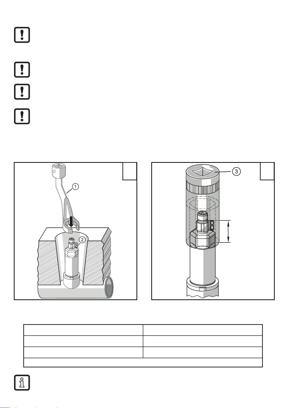
5 Installation����������������������������������������������������������������������������������������������������������10
5�1 G1A Aseptoflex Vario adaptation (PM17xx)������������������������������������������������� 11
5�2 Use in hygienic areas to 3-A������������������������������������������������������������������������12
5�3 Use in hygienic areas to EHEDG ����������������������������������������������������������������13
5�4 G1A sealing cone connection (PM16xx)������������������������������������������������������14
5�5 Protective cover�������������������������������������������������������������������������������������������15
5�5�1 Function ventilation diaphragm�����������������������������������������������������������15
5�5�2 Orientation of the filter cover ��������������������������������������������������������������15
5�6 Filter cover���������������������������������������������������������������������������������������������������16
6 Electrical connection������������������������������������������������������������������������������������������18
7 Parameter setting ����������������������������������������������������������������������������������������������19
7�1 Parameter setting via PC�����������������������������������������������������������������������������19
7�2 Parameter setting via the memory plug�������������������������������������������������������19
7�3 Teach offset with the teach button ���������������������������������������������������������������20
7�3�1 Scale analogue value �������������������������������������������������������������������������21
7�3�2 Select the standard unit of measurement (option)������������������������������21
7�4 User settings (optional)��������������������������������������������������������������������������������21

3
UK
1 Preliminary note
1.1 Symbols used
►Instruction
> Reaction, result
[…] Designation of keys, buttons or indications
→Cross-reference
Important note
Non-compliance may result in malfunction or interference�
Information
Supplementary note
7�4�1 Set damping for the analogue output �������������������������������������������������21
7�4�2 Set damping for the switching signal ��������������������������������������������������21
7�4�3 Zero-point calibration��������������������������������������������������������������������������21
7�4�4 List of the parameters�������������������������������������������������������������������������22
7�5 Diagnostic functions ������������������������������������������������������������������������������������22
7�5�1 Read min/max values for the system pressure ����������������������������������22
8 Operation�����������������������������������������������������������������������������������������������������������23
9 Error correction��������������������������������������������������������������������������������������������������23
10 Technical data and scale drawing��������������������������������������������������������������������24
11 Maintenance, repair, disposal ��������������������������������������������������������������������������24
12 Factory setting �������������������������������������������������������������������������������������������������24

4
2 Safety instructions
• The device described is a subcomponent for integration into a system�
- The manufacturer is responsible for the safety of the system�
- The system manufacturer undertakes to perform a risk assessment and to
create a documentation in accordance with legal and normative requirements
to be provided to the operator and user of the system� This documentation
must contain all necessary information and safety instructions for the operator,
the user and, if applicable, for any service personnel authorised by the
manufacturer of the system�
• Read this document before setting up the product and keep it during the entire
service life�
• The product must be suitable for the corresponding applications and
environmental conditions without any restrictions�
• Only use the product for its intended purpose (→ Functions and features).
• Only use the product for permissible media (→ Technical data).
• If the operating instructions or the technical data are not adhered to, personal
injury and/or damage to property may occur�
• The manufacturer assumes no liability or warranty for any consequences
caused by tampering with the product or incorrect use by the operator�
• Installation, electrical connection, set-up, operation and maintenance of the
product must be carried out by qualified personnel authorised by the machine
operator�
• Protect units and cables against damage�
3 Functions and features
The unit measures and monitors the system pressure of machines and
installations�
2 outputs are available:
- OUT1: Measured pressure value via IO-Link�
More information → 4.1 and → 7�
- OUT2: Analogue signal proportional to pressure 4���20 mA

5
UK
3.1 Detection zone
Type of pressure: relative pressure
Order
number Measuring range Pressure rating
(max. permissible pressure) *)
Bursting
pressure
Pressure sensors with G1 Aseptoflex Vario are certified in accordance with the hygienic
regulations 3-A and EHEDG
bar psi bar psi bar psi
PM1703 -1���25 -14�6…362�6 100 1450 350 5075
PM1714 -1���16 -14�6…232 75 1085 250 3625
PM1704 -1���10 -14�5…145 50 725 150 2175
PM1715 -1���6 -14�5…87 30 435 100 1450
PM1705 -1���4 -14�5…58 30 435 100 1450
mbar psi mbar psi bar psi
PM1706 -125���2500 -1�82…36�26 20000 290 50 725
PM1717 -100���1600 -1�45…23�21 15000 215 40 580
PM1709 -1000���1000 -14�5���14�5 10000 145 30 435
PM1707 -50���1000 -0�73���14�5 10000 145 30 435
PM1708 -12�5���250 -0�182���3�626 6000 84 30 435
PM1789 -5���100 -0�073���1�450 4000 58 30 435
Pressure sensors with G1 A sealing cone
bar psi bar psi bar psi
PM1602 -1���100 -15…1450 200 2900 650 9425
PM1603 -1���25 -14�6…362�6 100 1450 350 5075
PM1614 -1���16 -14�6…232 75 1085 250 3625
PM1604 -1���10 -14�5…145 50 725 150 2175
PM1615 -1���6 -14�5…87 30 435 100 1450
PM1605 -1���4 -14�5…58 30 435 100 1450
mbar psi mbar psi bar psi
PM1606 -125���2500 -1�82…36�26 20000 290 50 725
PM1617 -100���1600 -1�45…23�21 15000 215 40 580
mbar psi mbar psi bar psi
*) With static overload pressure�
MPa = (measured value in bar) ÷ 10
kPa = (measured value in bar) x 100

6
Order
number Measuring range Pressure rating
(max. permissible pressure) *)
Bursting
pressure
PM1609 -1000���1000 -14�5���14�5 10000 145 30 435
PM1607 -50���1000 -0�73���14�5 10000 145 30 435
PM1608 -12�5���250 -0�182���3�626 6000 84 30 435
PM1689 -5���100 -0�073���1�450 4000 58 30 435
*) With static overload pressure�
MPa = (measured value in bar) ÷ 10
kPa = (measured value in bar) x 100
Not suitable for systems that have to meet the criteria of E1�2 / 63-03 of
the 3-A standard 63-03�
The units are only permitted in gas applications with pressures >25 bar if
no elastomer sealing material is used for the adaptation of the sensor or if
a metal seal is used�
Avoid static and dynamic overpressure exceeding the indicated pressure
rating by taking appropriate measures�
The indicated bursting pressure must not be exceeded�
Even if the bursting pressure is exceeded only for a short time, the unit
may be destroyed�
CAUTION: Risk of injury!
The units are vacuum resistant�
4 Function
• The system pressure is detected by a ceramic-capacitive measuring system,
the measured signals are evaluated electronically�
• The unit converts the system pressure into an analogue output signal
(4���20 mA)�
• The unit has an IO-Link interface which allows to provide additional values:
- OUT1: Measured pressure value via IO-Link�
• Measured pressure value (cyclic output mode)
• Unit temperature (A-cyclic output mode)
• Diagnostic values
- OUT2: Analogue signal proportional to pressure 4���20 mA

7
UK
4.1 IO-Link
4.1.1 General information
This unit has an IO-Link communication interface which requires an IO-Link
capable module (IO-Link master) for operation�
The IO-Link interface enables direct access to the process and diagnostic data
and provides the possibility to set the parameters of the unit during operation�
In addition, communication is possible via a point-to-point connection with a USB
adapter cable�
The IODDs necessary for the configuration of the unit, detailed information about
process data structure, diagnostic information, parameter addresses and the
necessary information about the required IO-Link hardware and software can be
found at www�ifm�com�
4.1.2 Functions only available via IO-Link communication
• Device temperature: The internal temperature of the sensor can be read via the
A-cyclic IO-Link channel�
• Application-specific tag: freely definable text assigned to the unit�
• Function tag: freely definable text describing the device function in the plant�
• Location tag: freely definable text describing the installation location in the
plant�
For more detailed information refer to the device-specific IO Device Description
PDF at www�ifm�com�
4.1.3 Set-up via IO-Link
The device parameters can be set via IO-Link:
• The device parameters are set via the IO-Link interface (→ 4.1 and → 7)�
• All settings can also be carried out before installation of the device�
4.1.4 Process data via IO-Link
All process data is available via IO-Link:
• The unit is designed for fully bidirectional communication�
• The following options are available:
- Remote display: reading and displaying the current system pressure�
- Remote parameter setting: reading and changing the current parameters
via IO-Link parameter setting (→ 4�1)�

8
4.2 Defined state in case of a fault
• If a fault is detected, the analogue output passes into a defined state (=
21�5 mA)�
In case of a fault indication (= 21�5 mA):
►Read parameters via IO-Link or contact the manufacturer
4.3 Operating modes
The operating mode is defined by the wiring (→ 6 Electrical connection) and
automatically recognised by the unit�
4.3.1 2-wire operation
OUT2 (pin 2) Analogue signal proportional to pressure 4���20 mA
4.3.2 3-wire operation
OUT1 (pin 4) Communication via IO-Link
OUT2 (pin 2) Analogue signal proportional to pressure 4���20 mA
4.4 Analogue output
The device provides an analogue signal proportional to the pressure�
Within the measuring range the analogue signal is between 4 and 20 mA�
The measuring range is scalable:
• [ASP2] defines at which measured value the output signal is 4 mA�
• [AEP2] defines at which measured value the output signal is 20 mA�
Minimum distance between [ASP2] and [AEP2] = 20 % of the final value of
the measuring range�
If the measured value is outside the measuring range or in the event of an internal
error, the current signal indicated in figure 1 is provided�

9
UK
MEWMAW AEPASP
[% MEW]
P -1,25 0 100 103,13
4
3,8
20
20,5
21,5
[mA]
1
2
4
UL OL
3
5
Fig� 1: Output characteristics of the analogue output to Namur
1
Analogue signal
2
Measured value
3
Measuring range
4
Scaled measuring range
5
Signalling fault 21�5 mA (→ 9 Error correction)
P: Pressure
MAW: Initial value of the measuring range for non-scaled measuring range
MEW: Final value of the measuring range with non-scaled measuring range
ASP: Analogue start point with scaled measuring range
AEP Analogue end point with scaled measuring range
UL: Below the display range
OL: Above the display range

10
5 Installation
►Before installing and removing the unit make sure that no pressure is
applied to the system and there is no medium in the pipe�
►Note dangers related to extreme machine / medium temperatures�
►In case of a recessed sensor installation, please use an open ring
spanner or a hexagon socket with the corresponding inside contour�
►During sensor installation, do not exert any axial leverage with the
tool (1) on the rotatable filter cover (2) (→ Fig. 1)�
►In case of installation by means of a hexagon socket (3), make sure
that the tool's spanner flat has an inner height of at least 30 mm
(→ Fig. 2)�
Align the rotatable filter cover so that it is flush with one of the spanner
flats�
≥ 30mm
1 2
►Insert the unit in a process connection�
►Tighten firmly� Recommended tightening torque:
Process connection Tightening torque in Nm
G1A Aseptoflex Vario 35
G1A sealing cone 20
Depends on the sealing type, the pressure load and the lubrication!
A zero-point calibration of the measured value is possible via the teach
function (→ 7.3 Teach offset with the teach button)

11
UK
5.1 G1A Aseptoflex Vario adaptation (PM17xx)
►Insert the unit with process adapter into the process connection and tighten
using a spanner�
Information about available adapters at www�ifm�com�
►Observe the instructions of the adapter�
►Use a lubricating paste which is suitable and approved for the
application�
The unit can be fixed to different process connections�
Options are as follows:
1Installation using an adapter with sealing ring (hygiene-compliant)
Order no� E332xx / E333xx�
►To meet the hygiene regulations use a process adapter with leakage
port�
The adapters are supplied with EPDM O-ring (order no� E30054)�
More sealing rings are available as accessories:
• FKM O-ring (order no� E30123)
• PEEK sealing ring (order no� E30124)� The PEEK sealing ring is long-
term stable and maintenance-free�
►When you replace the PEEK sealing ring or change from a PEEK sealing
ring to an O-ring, the process adapter also needs to be replaced with a
new equivalent adapter�
2Installation using a welding adapter with sealing ring (hygiene-
compliant)
►To meet the hygiene regulations use a process adapter with leakage
port�
►Make sure that the process adapter does not warp during welding� Use
welding mandrel E30452�
►The sealing edge must not be damaged by subsequent surface
treatment. (→ Instructions in operating instructions of the adapter).
The adapter is supplied with EPDM O-ring (order no� E30054)�
Another sealing ring is available as accessory:
• FKM O-ring (order no� E30123)�

12
3Installation using a process adapter with metal-to-metal seal
Order no� E337xx / E338xx
A long-term stable and maintenance-free fitting without bug traps in
the metal-to-metal seal is only valid for once-only mounting�
►If the sealing has to be installed several times, use a new adapter�
4Installation to G 1 flange / G 1 bush
The sensor is sealed with the sealing ring at the back of the process
connection�
►The sealing area at the flange / bush must be flush with the tapped hole
and have a surface characteristic of min� Rz = 6�3�
5.2 Use in hygienic areas to 3-A
The following applies to units with 3-A
certification:
►Only use adapters with 3-A
certification for the process
connection�
►Do not install the unit at the lowest
point of the pipe or tank (→ position
5) in order that the medium can
run off the area of the measuring
element�

13
UK
5.3 Use in hygienic areas to EHEDG
The sensor is suited for CIP (cleaning in process) when installed correctly�
►Observe the application limits (temperature and material resistance)
according to the data sheet�
►Make sure that the sensor is integrated into the system according to EHEDG:
►Use self-draining installation�
►Only use process adapters permitted according to EHEDG with special seals
required by the EHEDG position paper�
The gasket of the system interface must not be in contact with the
sealing point of the sensor�
►In case of structures in a tank, the installation must be flush mount� If not
possible then direct water jet cleaning and cleaning of dead spaces must be
possible�
►Leakage ports must be clearly visible and must be installed facing downwards
for vertical pipes�
1
D
L
►To avoid dead space adhere to the
dimensions:
L < (D)�
1: Leakage port

14
5.4 G1A sealing cone connection (PM16xx)
Information about available adapters at www�ifm�com�
►Observe the instructions of the adapter�
A guarantee for a long-term stable and maintenance-free fitting, with
no bug traps in the sealing of the metal seal is only valid for once-only
mounting�
The unit can be fixed to different process connections�
Options are as follows:
1Installation using a clamp adapter
Order no� E3360x
Information about available adapters at www�ifm�com�
►Observe the instructions of the adapter�
►Use a lubricating paste which is suitable and approved for the
application�
►Recommended tightening torque 35 Nm�
The adapter E33602 is supplied with an EPDM-O-ring (order no� E30438)
and an FKM O-ring (order no� E30437)�
2Installation using a welding adapter
Order no� E30013 sealing: metal to metal
order no� E30072 sealing: with sealing ring
Information about available adapters at www�ifm�com�
►Observe the instructions of the adapter�
►Make sure that the process adapter does not warp during welding�
►Use a lubricating paste which is suitable and approved for the
application�
The adapter E30072 is supplied with an EPDM-O-ring (order no� E30438)
and an FKM O-ring (order no� E30437)�

15
UK
3Installation using an adapter G 1 to G ½
Order no� E30116
Information about available adapters at www�ifm�com�
►Observe the instructions of the adapter�
►Use a lubricating paste which is suitable and approved for the
application�
►Recommended tightening torque 20 Nm�
5.5 Protective cover
5.5.1 Function ventilation diaphragm
The ventilation diaphragm enables the relative pressure measurement since
barometric and temperature-dependent pressure fluctuations between the
measuring cell and the environment are compensated for�
The ventilation diaphragm is protected against damage by a screwed cap with
circumferential ports�
For a correct functioning of the diaphragm please take the following into
account:
►Remove soiling and cleaning agents immediately using plenty of lime-
deficient splash water�
If the sensor is in a cooling stage:
►Avoid contact of the diaphragm with liquids:
> Avoids negative pressure in the measuring system resulting in a slightly
falsified measured value and additional strain on the diaphragm�
5.5.2 Orientation of the filter cover
The filter cover is freely rotatable around the sensor's axis and thus adaptable to
the environmental conditions�
When the sensor is mounted in a vertical position, the condensate escapes
through the ports in the protective cap due to gravity�
When the sensor is mounted in a horizontal position or similar, the filter protection
cap must be rotated towards one of the two lateral faces to bring the GORE
diaphragm into a vertical position� This guarantees the optimum drainage for
liquids�

16
To ensure an optimum function of the pressure compensation element,
align the filter cover as shown in Fig� 1�
3
1
2
►Ideal orientation (1):
Filter cover in horizontal position�
The ventilation diaphragm (2)
in the filter cover is in a vertical
position�
►Maximum inclination: 30° (3)
Fig� 1: Orientation
5.6 Filter cover
Replace filter cover:
1Exchange the filter cover incl� GORE diaphragm (E30142)�
2Replace the filter cover with a closed version (E30148) (*)
Improve the protection of the filter cover:
3Replace the filter cover with a version with a tube fitting and a vent tube that ends in a
protected and dry area (E30139)�
4Set of accessories (E30467) with integrated replacement diaphragm (GORE) for high
degree of soiling and / or high climate pollution�
Function: (→ Installation instructions E30467)
►Avoid soiling and moisture during the exchange
►Clean the thread carefully and without residues
►Do not damage the adhesive area of the sensor
►Observe the orientation of the filter cover
(→ Installation instructions E30139 / 30467)

17
UK
123
4
(*)When using the closed cover cap, there is no pressure compensation
of the measuring cell any more� This results in measurement deviations
caused by:
• fluctuations of the atmospheric pressure
• pressure fluctuations inside the unit in case of temperature changes
(Δ 10 K ≤ 30 mbar).

18
6 Electrical connection
The unit must be connected by a qualified electrician�
The national and international regulations for the installation of electrical
equipment must be adhered to�
Voltage supply according to EN 50178, SELV, PELV�
►Disconnect power�
►Connect the unit as follows:
Core colours
43
2 1
2-wire operation (2w)
WH
1
2
BN
L+
OUT2
1 BN brown
2 WH white
3 BU blue
4 BK black
3-wire operation (3w)
BN
WH
BK
BU
4
1
3
2OUT2
L+
L
OUT1
OUT1: communication via IO-Link
OUT2: analogue output
Colours to DIN EN 60947-5-2
Wiring example
(2w) 1 x analogue (3w) 1 x analogue
L
1L+
2
BN
WH
L
L
+
3
2
1
BU
WH
BN
(3w) 1 x analogue / 1 x IO-Link (3w) 1 x IO-Link
L
L
+
3
4
2
1
BU
BK
WH
BN
IO-Link
L
L
+
3
4
1
BU
BK
BN
IO-Link

19
UK
EMC test to EN 61000-4-5 Surge: 0�5 kV
7 Parameter setting
The unit can be configured via the IO-Link function�
►Prepare IO-Link hardware and software for parameter setting�
►Connect the unit with e�g� an IO-Link interface (→ 7.1) or a programmed
memory plug (→ 7.2)�
►Set the parameters�
►Put the unit into operation�
The parameters can be set before installation or during operation�
Changing parameters during operation can influence the function of the
plant�
►Ensure that there will be no malfunctions in your plant�
7.1 Parameter setting via PC
For parameter setting, an IO-Link-capable software is necessary
(e�g� LR DEVICE)�
IO-Link interfaces from ifm are available for the connection of the unit via the USB
interface of a computer → www.ifm.com.
►Prepare computer, software and interface�
►Connect the unit with the IO-Link interface�
►Follow the menu of the IO-Link software�
►Set the parameters�
►Put the unit into operation�
Adjustable parameters (→ 7.4.4)�
7.2 Parameter setting via the memory plug
A parameter set can be written to the unit / can be recorded by the unit via a
memory plug (ifm storage module) → www.ifm.com.
In order to allow for data to be written from the memory plug to the sensor,
the sensor must have the factory setting�

20
If the sensor has been configured, the memory plug records the parameter
set which can then be transferred to other sensors of the same type�
►Load a suitable parameter set (e�g� from a PC or from a sensor of the same
type) to the memory plug�
►Connect the memory plug between sensor and socket�
> Sensor with factory setting:
When voltage is supplied, the parameter set is transferred from the memory
plug to the sensor�
> Sensor with changed settings:
When voltage is supplied, the memory plug records the sensor's parameter set�
►Remove the memory plug�
►Put the unit into operation�
Adjustable parameters (→ 7.4.4)�
You can find more information about the memory plug in the corresponding
technical documentation → www.ifm.com.
7.3 Teach offset with the teach button
An external teach button (E30425) allows for a zero-point calibration (calibration
offset)� The current measured value is taken as internal zero point if this measured
value lies within a range of +/- 3% of the measuring span�
For connection information see the data sheet of E30425
If a teach button is connected, no IO-Link communication is possible
►Integrate the teach button between the installed sensor and the supply cable�
►Maintain the plant pressure constantly at zero (configurable range = +/- 3% of
the measuring span)�
►Press the button for > 2 ��� < 10 s�
> When voltage is supplied, the LED in the button flashes at 2 Hz and configures
the zero point (calibration offset)�
> In case of a fault, the LED flashes at 8 Hz�
This manual suits for next models
1
Table of contents
Other IFM Accessories manuals