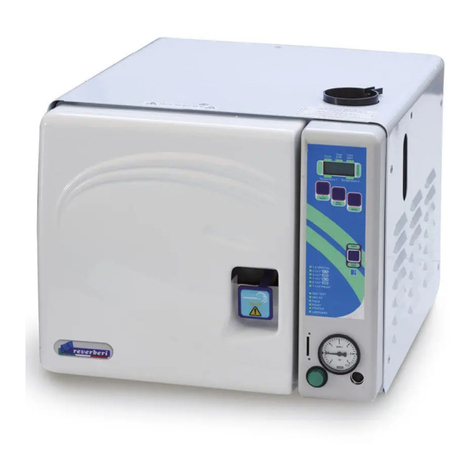
Tuttnauer 6671130 Manual

OPERATION
&
MAINTENANCE
MANUAL
Pre-Vacuum Steam Heated Autoclave
with one Vertical Sliding Door
and a 36 kW Steam Generator
Model 6671130 2VEP
S.N: 1102058
Cat. No.: MAN205-0195042EN Rev A Aug. 2011
Tuttnauer. Ltd., Har Tuv Industrial Zone, B P.O. Box 170, Beit Shemesh, 99000, Israel, Tel:972 2 9904611
Fax:972 2 9904730
Tuttnauer Europe b.v., Hoeksteen 11, 4815 PR Breda Breda, P.O. Box 7191, 4800 GD Breda, Netherlands.
+31/76-5423510, Fax: +31/76-5423540

Web site: http//www.tuttnauer.com

MAN205-0195042EN Rev. A Aug. 2011
i
Table of Contents
INCOMING INSPECTION ---------------------------------------------------------------------------1
SAFETY INSTRUCTIONS---------------------------------------------------------------------------2
1. GENERAL INFORMATION
1.1 Introduction ---------------------------------------------------------------------------------------4
1.2 Front Panel ---------------------------------------------------------------------------------------8
1.3 Standards -----------------------------------------------------------------------------------------9
1.4 Specifications ------------------------------------------------------------------------------------9
1.5 Symbol Descriptions ---------------------------------------------------------------------------10
1.6 Utility Labels--------------------------------------------------------------------------------------10
2. INSTALLATION
2.1 Environmental Conditions --------------------------------------------------------------------11
2.2 Mounting-------------------------------------------------------------------------------------------11
2.3 Preliminary Check ------------------------------------------------------------------------------14
3. FUNCTIONAL DESCRIPTION
3.1 The Steam Generator--------------------------------------------------------------------------16
3.1.1 Generator Electrical Safety System---------------------------------------------17
3.1.2 The Water Pump for the Steam Generator------------------------------------17
3.1.3 GICAR Water Level Controller----------------------------------------------------18
Generator Electrical Layout ------------------------------------------------------------------19
Generator Electrical Diagram----------------------------------------------------------------20
Generator Control Electrical Cascade Diagram-----------------------------------------21
3.2 The Piping System------------------------------------------------------------------------------22
Piping System Drawing------------------------------------------------------------------------24

MAN205-0195042EN Rev. A Aug. 2011
ii
Table of Contents (Cont.)
3.3 The Pneumatic Control System-------------------------------------------------------------25
Pneumatic Control System Drawing -------------------------------------------------------26
3.4 Absolute Pressure Transducers-------------------------------------------------------------27
3.5 The Vacuum Pump and the Heat Exchanger--------------------------------------------28
3.6 The Electrical System--------------------------------------------------------------------------29
3.7 The Control System ----------------------------------------------------------------------------31
Safety Interlock Devices ----------------------------------------------------------------------34
Electrical Control System Drawing ---------------------------------------------------------35
3.8 Water Quality-------------------------------------------------------------------------------------36
4. CONTROL AND MONITORING
Control Panel CAT 2007 ----------------------------------------------------------------------37
4.1 Description of panel CAT 2007--------------------------------------------------------------37
4.1.1 KeyPad----------------------------------------------------------------------------------38
4.1.2 Display ---------------------------------------------------------------------------------40
4.2 Description of Displayed Messages and Safety Measures --------------------------42
4.3 Operating the Control Panel -----------------------------------------------------------------44
4.3.1 Starting up the system--------------------------------------------------------------44
4.3.2 Selecting a Cycle---------------------------------------------------------------------45
4.3.3 System Setup (Changing Parameters and Values)-------------------------49

MAN205-0195042EN Rev. A Aug. 2011
iii
Table of Contents (Cont.)
4.3.4 Changing Cycle Parameters ------------------------------------------------------52
4.3.5 Door Display Function --------------------------------------------------------------57
4.3.6 Display During a Cycle--------------------------------------------------------------58
5. PRINTER
5.1 Printer Output------------------------------------------------------------------------------------59
5.2 Printer Handling ---------------------------------------------------------------------------------61
6. STERILIZATION PROGRAMS
6.1 Program Descriptions--------------------------------------------------------------------------63
7. PREPARATION BEFORE STERILIZATION--------------------------------------------70
7.1 Loading --------------------------------------------------------------------------------------------71
7.2 Un-loading ----------------------------------------------------------------------------------------72
8. OPERATING INSTRUCTIONS -------------------------------------------------------------74
8.1 Failed Cycle --------------------------------------------------------------------------------------75
8.2 Aborting a Cycle---------------------------------------------------------------------------------76
8.3 Switching to the Internal Steam Generator-----------------------------------------------77
SERVICE INSTRUCTIONS
9. MAINTENANCE OF THE AUTOCLAVE
9.1 Preventive and Period -------------------------------------------------------------------------80
9.2 Safety Tests after Repair ---------------------------------------------------------------------84
9.3 General Troubleshooting----------------------------------------------------------------------85
9.4 Steam Generator Troubleshooting ---------------------------------------------------------90
9.5 Troubleshooting for Water Pump SHURFLO--------------------------------------------92

MAN205-0195042EN Rev. A Aug. 2011
iv
Table of Contents (Cont.)
9.6 The SHURFLO Water Pump Rear Endbell Replacement Kit -----------------------93
9.7 Generator Maintenance -----------------------------------------------------------------------95
9.7.1 Generator Pressure Switches-----------------------------------------------------95
9.7.2 Cleaning and Replacing the Water Level Electrodes-----------------------96
9.7.3 Replacing the Heaters --------------------------------------------------------------98
9.7.4 Replacing the Generator Side Gauge Glass Indicator Tube--------------99
9.8 Releasing the Vacuum Pump Rotor--------------------------------------------------------100
9.9 Test Points - Cat 2007-------------------------------------------------------------------------101
9.10 Calibration-----------------------------------------------------------------------------------------102
9.10.1 Calibrating Temperature and Pressure-----------------------------------------103
9.10.2 An Example of Temperature Calibration---------------------------------------105
9.11 Working with power ON in Service Area (Autoclaves with sliding doors)--------106
9.12 Testing the Safety Valves---------------------------------------------------------------------107
9.13 Replacing the Door Gasket-------------------------------------------------------------------109
9.14 Servicing the Vertical Door Operation Cylinder-----------------------------------------110
10. SPARE PARTS ---------------------------------------------------------------------------------111
11. VALVES NUMBERING -----------------------------------------------------------------------116
12. PRESSURE Vs TEMPERATURE for SATURATED STEAM----------------------118
XPCS MANUAL---------------------------------------------------------------------------------123
MODEM CONNECTION ----------------------------------------------------------------------137
Set of Drawings

MAN205-0195042EN Rev. A Aug. 2011
Page 1 of 137 pages
INCOMING INSPECTION
Upon receipt, the autoclave should be unpacked and inspected for mechanical damage.
Observe packing method and retain packing material until the unit has been inspected.
Mechanical inspection involves checking for signs of physical damage such as:
scratched panel surfaces, broken knobs, etc.
If damage is apparent, file a claim with the carrier. The manufacturer is responsible for
products supplied Ex Factory. These products are carefully inspected prior to shipment
and all reasonable precautions are taken in preparing them for shipment to assure safe
arrival at their destination.
WARRANTY
We certify that this device is guaranteed to be free from defects in material and
workmanship for one year against faulty components and assembly with the exception
of glassware, lamps and heaters.
The warranty does not include and does not replace routine treatment and preventive
maintenance to be performed according to instructions in the Preventive and Periodical
Maintenance paragraph.
Our obligation is limited to replacing the device or parts, after our examination, if within
one year after the date of shipment if they prove to be defective. This warranty does not
apply to any device that has been subjected to misuse, neglect, accident or improper
installation or application, nor shall it extend to products, which have been repaired or
altered outside the factory without prior authorization from us.
The autoclave should not be used in a manner not described in this manual!
Note:
If there is any difficulty with this instrument, and the solution is not covered in
this manual, contact our representative or us first.
Do not attempt to service this instrument yourself.
Stipulate the model and serial number and describe the difficulty as clearly as possible
so that we may be able to identify the problem and hence provide a prompt solution.
For technical information or service please contact:
PARAMEDICOS de EL SALVADOR
Prolongacion Calle Arce,
Edificio # 3020,
Entre 57 Y 59,
Av. Norte.
San Salvador,
EL SALVADOR.
Tel: 2265-2099

MAN205-0195042EN Rev. A Aug. 2011
Page 2 of 137 pages
Safety Instructions
The autoclave has unique characteristics. Please read and understand the operation
instructions provided by the manufacturer before the first operation of the autoclave. The
following issues may require clarification: The operation of the autoclave; the door safety
mechanism; the door closing mechanism; the dangers involved in circumventing safety
means; and finally, the selection of an appropriate sterilization program.
Make sure that you know the placement of the main power switch, the position of the
water cut-off valve, where the steam and compressed air disconnection valves are
located.
Autoclave maintenance is crucial for the correct and efficient function of the device.
The daily B&D test and the weekly spore test are part of the preventive maintenance
plan, along with the annual validation of the sterilization processes that ensures
appropriate temperature dispersion within the chamber.
Warning!
Never use the autoclave for the sterilization of corrosive products and chemicals ,
such as: Acids, bases and phenols, volatile compounds or solutions such
ethanol, methanol or chloroform nor radioactive substances.
Safety Operation Instructions
1. NEVER start a new autoclave or a new steam generator, before the safety,
licensing, and authorization department has not approved it for use.
2. All autoclave users must receive training in proper usage from an experienced
employee. Every new employee must undergo a training period under an
experienced employee.
3. A written procedure must be established for autoclave operation, including:
Daily safety tests; seal inspection and door hinge inspection; smooth action of
the closing mechanism; chamber cleaning; prevention of clogging;
preservation from corrosion; and finally, what is permitted and what is
prohibited for sterilization and choosing a sterilization program.
4. If there is a steam generator –drain it daily.
5. If there is an air compressor –drain it daily.
6. Before use, check inside the autoclave chamber to ensure that no items have
been left from a previous cycle.
7. Before loading the autoclave, clean the strainer on the chamber floor.
8. Load trays in such a way as to allow steam to move freely among all items.
9. Liquids may be sterilized only with the ―liquids‖ program. The container must
be covered but not sealed. Sealed bottles may only be sterilized using a
special program. The bottle must be either Pyrex or a Borosilicate glass bottle.
10. When sterilizing plastic materials, make sure that the item can withstand
sterilization temperature. Plastic that melts in the chamber is liable to cause a
great deal of damage.

MAN205-0195042EN Rev. A Aug. 2011
Page 3 of 137 pages
11. Individual glass bottles may be placed within an appropriate container that will
be placed on a tray. Never place glass bottles on the floor of the autoclave.
Never fill more than 2/3 of the bottle volume.
12. On closing the autoclave door, make sure that it is properly locked before
activating.
13. Verify once again that you have chosen the appropriate sterilization program.
14. Before withdrawing trays, wear heat resistant gloves.
15. Before opening the door, verify that there is no pressure in the chamber
(chamber pressure gauge is located on the autoclave's front panel).
16. Open the door slowly to allow steam to escape and wait 5 minutes before you
remove the load. When sterilizing liquids, wait 10 minutes.
17. Once a month, ensure that the safety valves are operating; and once a year,
that a certified inspector performs a chamber pressure safety test.
18. Once annually, or more frequently, effective tests must be performed, i.e.,
calibration and validation.
19. Check the condition of assemblies on a regular basis. Make sure there are no
leaks, breaks, blockages, whistles or strange noises.
20. Perform maintenance operations as instructed.
21. Notify the person in charge immediately of any deviation or risk of proper
function of the device.
22. It is strictly forbidden for any person to enter the autoclave‘s chamber. If, for
any reason (for cleaning, maintenance or if something falls down), it is
necessary to enter the chamber, the person must lock the system with the key
and take the key with him.
Instructions for Contaminated Waste
1. Verify that the contaminated waste at the sterilization station is packed in the
correct bags/containers.
2. Verify that there are no leaks and that the package is correctly marked.
3. Large containers with a narrow spout may ―behave‖ like a sealed bottle.
4. It is preferable to sterilize solutions in small containers rather than in
differently-sized containers or in large containers.
5. It is recommended not to stand in front of the door when it opens, because
steam may be discharged when the door is opened.
6. It is recommended to support sterilization bags at the bottom –especially
when they are hot.
Attention:
IF THE UNIT IS USED IN MANNER NOT SPECIFIED BY THE MANUFACTURER,
THE PROTECTION PROVIDED BY THE EQUIPMENT MAY BE IMPAIRED.
KEEP THE DOOR CLOSED DURING THE DAY OR SHIFT. WHEN THE AUTOCLAVE
IS NOT OPERATING, AT NIGHT OR ON THE WEEKEND, LEAVE THE DOOR OPEN.

MAN205-0195042EN Rev. A Aug. 2011
Page 4 of 137 pages
1. GENERAL INFORMATION
1.1 Introduction
This autoclave is designed to cover a large field of applications for hospitals and medical
centers as well as pharmaceutical and biotechnological industries.
The autoclave operates with saturated steam as the sterilizing agent, and has a
temperature range of up to 137C (279ºF) and pressure up to 2.3 bar (34 psi).
The autoclave is equipped with a 36 kW built-in steam generator. This steam generator
acts as a standby if building steam is not available for the sterilization process.
The autoclave is built to receive two steam supply sources, namely from the building, or
from an internal built in steam generator. There is a selector switch on the Front Panel to
choose the source. Before selecting the external generator, check the generator is
connected to the electrical supply and working properly.
The autoclave is equipped with two vertical sliding doors. Each door is operated by two
hydro-pneumatic cylinders mounted laterally on both sides of the door. Each cylinder
contains an integrated and separated oil system. The operation of the cylinders is
performed by air pressure and the oil system acts as a speed control system. An
adjustable restrictor controls the flow of oil from one side to the other side on each
cylinder, controlling the speed movement of the door. (For servicing of the unit see the
SERVICING INSTRUCTIONS chapter.)
The autoclave is mounted through a recessed wall. The two doors are located in two
separate rooms.
The front door, on the side of the master control panel is in the preparation area, from
where the autoclave is operated and serves for loading the material into the sterilization
chamber. This area is known as the "dirty side." The rear door is located on the "clean
side" and serves for unloading the sterilized material from the autoclave. This side of
autoclave is equipped with secondary control panel (slave).
The sealing of the chamber is achieved through a heat resistant silicone gasket, located
in a groove around the door opening of the autoclave. The gasket is pressed against the
door by steam pressure introduced into the groove behind the gasket.
The interlocking system of the door is based on the following opening conditions:
A door cannot be opened while the autoclave is in operation.
A door cannot be opened if the chamber is under pressure.
A door cannot be opened if there is liquid in the chamber.
Both doors cannot be opened at the same time. Opening of one door
automatically locks the other.

MAN205-0195042EN Rev. A Aug. 2011
Page 5 of 137 pages
After opening the door on the dirty side, even after closing it and it being
locked and sealed, the door on the clean side can be opened only after
performing a complete sterilization cycle.
If cycle failed, the front door only can be opened.
After test cycle, the front door only can be opened.
A door cannot be opened at the end of the cycle if the chamber temperature is
higher than the preset final temperature.
The electronic circuitry and software programming of the programmable control system
are designed to operate 10 sterilization programs. Three programs are intended for un-
wrapped instruments, four for wrapped instruments and packs, three for slow exhaust
pressure cycles. In addition, there are two test programs: Bowie & Dick Test and the
Leakage Test.
The control system of the sterilizer is based on microcomputer technology, ensuring a
highly reliable and safe operation. The computerized control unit ensures a fully
automatic operation through the entire cycle; hence, after setting the pre-selected
parameters and starting the operation, no further operator intervention is necessary.
The autoclave has an automatic shutdown system. If no buttons or switches are
operated for four hours, it will go into SLEEP MODE and a LED lights up (blinking every
second), indicating that the system is in the SLEEP MODE.
The selected program, the main phases of the cycle and the status of the machine are
controlled and displayed on digital readouts. For process documentation, the important
information concerning operation is printed.
The system is equipped with two temperature sensors,four pressure transducers, five
pressure gauges, and safety devices having the following functions:
The temperature sensors:
1. In the drain –(control)
2. In the condensate line(double) –(control, monitoring, and printout)
The pressure transducers measure:
1. Chamber pressure –(control, display, and printout)
2. Jacket pressure –(control and monitoring)
3. Door 1 gasket pressure –(control and monitoring)
4. Door 2 gasket pressure –(control and monitoring)

MAN205-0195042EN Rev. A Aug. 2011
Page 6 of 137 pages
The pressure gauges:
Front Panel
Service Area
1. Chamber pressure
2. Jacket pressure
3. Door 1 gasket pressure
4. Door 2 gasket pressure
5. Steam generator pressure
The safety devices:
1. RT112 pressure switch –(prevents the opening of the door if there is
pressure in the chamber)
2. Two ALCO pressure switches –(prevents the operating of the door if
there is no vacuum in the door gasket)
3. RANCO over pressure switch –(control the over pressure of the steam
generator)
4. SMS VM830 end switch –(prevents the pressurizing of the chamber
and the door gasket if the door is not closed)
5. Two Safety Bars –(prevent the door from trapping any object while
closing)
6. A GICAR controller connected to a water level electrode in the chamber
prevents opening of the door if there is liquid in the chamber.
The keyboards located on both the front and rear panels enables the operator to select a
sterilization program, start/stop a cycle, and close or open a door.
A programming mode, which can be accessed by a code from the front panel only,
enables the technician to set up the system, set and change a number of additional
parameters and operational modes and performing a calibration.
Optionally, a personal computer can be connected to the control system, through the
interface board RS232, which can be operated up to 8 meters away from the autoclave.
The PC, operating under WINDOWS displays the status, data and processing in real
time in graphic and digital form at the same time recording and logging the data. For a
distance more than 8 meters, a RS485 interface and a modem are required.
The communication PC-control unit enables the complete control of the autoclave
through the PC, including program selection, starting and stopping a cycle, setting of
parameters, and the real time clock (date and time of the day).
The autoclave is equipped with ―Emergency Stop‖ push-buttons and key locks, mounted
on both the front and rear panel. This feature is designed to prevent human hazards,
accidents or equipment breakdown in compliance with the European standards EN-285
requirements.

MAN205-0195042EN Rev. A Aug. 2011
Page 7 of 137 pages
Warning!
Do not operate the autoclave in the presence of dangerous gases and vapors.
It is strictly forbidden to enter the autoclave chamber!
If, for any reason (for cleaning, maintenance or if something falls down), it is
necessary to enter the chamber, the person must lock the system by pressing the
emergency switch and take the key with him to prevent accidents and
unauthorized use.
When emergency switch is activated, the key must be used to allow the switch to return
to the operating position.
Warning!
It is strictly forbidden for any person to enter the service area behind the service
access panels, except the trained technician.
If, for any reason it is necessary to open the service access panel, the person
must shut the system by pressing the emergency switch, withdrawing the key and
keeping the key on him, to prevent accidents and injuries.
The technician must follow the instructions in the SERVICE INSTRUCTIONS,
“Working with power ON in Service Area” Section.

MAN205-0195042EN Rev. A Aug. 2011
Page 8 of 137 pages
1.2 Front Panel
Legend:
1. Pressure Gauges
2. Emergency STOP Switch
3. Operation Panel
4. Printer
5. Operating Switch
6. Steam Selector Switch
7. Chamber
8. Service Access Panel
7
5
2
3
1
4
6
8

MAN205-0195042EN Rev. A Aug. 2011
Page 9 of 137 pages
1.3 Standards
Tuttnauer. Ltd. company meets the provisions of the Medical Device Directive
93/42EEC and PED 97/23EEC and the following standards:
ASME American Society of Mechanical Engineers
Section VIII, Division 1, for unfired pressure vessels.
AAMI/ANSI-ST8 Hospital sterilizers
EN 285 Large Sterilizers.
EN 554 Validation and routine control.
UL UL 61010-1
IEC IEC 61010-2-040 Safety
Tuttnauer. Ltd. is also approved for:
ISO 9001:2008 (Quality Systems)
ISO 13485:2003 (Quality Systems for Medical Devices)
ISO 17665-1:2006 (Validation and Routine Control)
1.4 Specifications
Product data
Model 6671130 2VEP
Chamber capacity
610 l
Chamber dimensions
W
660 mm 26"
H
710 mm 28"
D
1300 mm 51"
External dimensions
W
1040 mm 41"
H
2020 mm 80"
L
1720 mm 68"
Degree of protection
IPX 4
Utilities
Tap Water supply
Maximum hardness value 0.7-2.0 mmol/l
Recommended temperature 15°C (60°F)
1. Connection: ½" thread
2. Pressure: 2–5 bar (30–70 psi)
Steam
1. Connection: ¾" thread
2. Pressure: 3.5–4.5 bar (60–65 psi)
Distilled or Mineral free water
1. Connection: ½" thread
2. Pressure: 2–5 bar (30–70 psi)
See chapter "Water Quality"
Compressed air requirements
1. Connection: ¼" thread
2. Pressure: 6–8 bar (85–115 psi)
3. Consumption: 100 LPM
Electrical data
3 Ph, 208V/ 60Hz, 105 A
Electrical cable requirements
5X50mm2

MAN205-0195042EN Rev. A Aug. 2011
Page 10 of 137 pages
1.5 Symbol Description
Symbol
Description
Caution! Consult accompanying documents
Caution! Hot surface
Caution! Hot steam
Protective earth (Ground)
1.6 Utility Labels
Utility
Specification
Mineral Free Water
2–5 bar (30–70 psi)
Steam
3.5–4.5 bar (60–65 psi)
Tap Water
2–5 bar (30–70 psi)
Compressed Air
6–8 bar (85–115 psi)
Electricity
3 Ph, 208V/ 60Hz, 105 A

MAN205-0195042EN Rev. A Aug. 2011
Page 11 of 137 pages
2. INSTALLATION
2.1 Environmental Conditions
Ensure all shut-off valves or switches from the building services to the autoclave, for
example compressed air, electricity, steam, water, etc. are clearly marked, and are
located in an easy to reach, unrestricted area.
Ensure all personnel working with or around the autoclave are properly trained in the
location of all the shut off valves and switches that supply services from the building to
the autoclave.
The ambient atmosphere around the autoclave must not exceed 40 ºC (104 ºF), 80%
relative humidity, and the room should be ventilated 10 air changes/hour.
Place warning signs related to the possible dangers of operating autoclaves in
prominent positions. See the Symbol Description paragraph for explanations of the
dangers.
Warning!
Do not use the autoclave in presence of dangerous gases and vapors.
2.2 Mounting
Place the autoclave on a suitable level surface, leaving adequate space around it for
operation and service requirements.
Level the autoclave before connecting the utilities.
Utilities
Connect the autoclave to the utility supplies as follows:
Air
Connect the air connection of the autoclave to the compressed air supply of the building
by means of a ¼‖ pipe at 6–8 bar (85–115 psi).
Water
The autoclave is supplied by two water systems:
1. Tap Water
Tap water for the vacuum pump and cooling the heat exchanger;
Hardness should not exceed 0.7–2 mmol/l See also chapter "Water
Quality".
Pressure should be in the range of 2–5 bar (30–70 psi)
Connection to the network by a ½‖ pipe.
2. Distilled or Mineral Free Water
Distilled or mineral free water for the steam generator.
Connect the distilled or mineral free water reservoir to a distilled or mineral
free water supply source by a ½" pipe.
Pressure should be in the range of 2–5 bar (30–70 psi)
See also the Water Quality paragraph!
Attention
Connection of water systems to the autoclave must be performed through "BACK
FLOW PREVENTION SYSTEM" installation as per EN 1717 regulations and local
regulations.

MAN205-0195042EN Rev. A Aug. 2011
Page 12 of 137 pages
Drain
Connect the following outlets directly to the drain funnel. or connect them
through a drain collector pipe of 4-6‖ that should be covered. The drain
system should be vented.
General drain outlet by a ¾" pipe.
Vacuum pump by a 1" pipe
Steam
Connect the building steam supply to the autoclave inlet by a ¾" pipe.
The steam supply pressure should be between 3.5–4.5 bar (50-65 psi).
(See also Utilities Table).
The steam trap on the building steam supply should not exceed 2 meters
from the machine.

MAN205-0195042EN Rev. A Aug. 2011
Page 13 of 137 pages
Electrical Power Connection
Warning!
Only a qualified electrician may perform the electrical connections!
The electrical units should not be placed near water sources.
Connect the power cord to the electric box of the autoclave
Electrical data
3 Ph, 208V/ 60Hz, 105 A
Electrical cable requirements
5 X 50 mm2
Note:
Before operating the vacuum pump, make sure that the pump shaft is free and
you can turn it with a screw driver.
Warning!
It is strictly forbidden to enter the autoclave chamber!
If, for any reason (for cleaning, maintenance or if something falls down), it is
necessary to enter the chamber, the person must lock the system by pressing the
emergency switch and take the key with him to prevent accidents and
unauthorized use.
Warning!
It is strictly forbidden for any person to enter the service area behind the service
access panels, except the trained technician.
If, for any reason it is necessary to open the service access panel, the person
must shut the system by pressing the emergency switch, withdrawing the key and
keeping the key on him, to prevent accidents and injuries.
The technician must follow the instructions in the SERVICE INSTRUCTIONS,
“Working with power ON in Service Area” Section.

MAN205-0195042EN Rev. A Aug. 2011
Page 14 of 137 pages
2.3 Preliminary Check
After installation, and prior to putting the machine into operation, the following checkout
procedure is to be fulfilled:
Check the connection to local sewage. Check that the sewage pipeline is
not clogged. (Pour water for this task).
Check the connection to compressed air, pay attention to the door, set the
pressure to 6-8bar.
Check the connection to tap water. Open the water valve. Manually test the
water valves by over-riding the appropriate solenoid valve. If there are no
leaks –rotate backwards the solenoid by-pass. Leave the manual inlet taps
open.
Check the connection to mineral-free water. Open the water valve. Test
manually the water valves by over-riding the appropriate solenoid valve. If
there are no leaks, rotate backwards the solenoid by-pass. Leave the water
manual inlet taps open.
Close the building manual steam inlet valve, and turn OFF Building inlet
using the ON-OFF-ON switch on the front panel.
Open the generator electric box, switch ON the 3 Phase circuit breaker with
it‘s Trip Coil, and ensure all the other circuit breakers are ON.
Turn ON Generator steam inlet using the ON-OFF-ON switch on the front
panel.
Check that the jacket pressure gauge, reaches 2.4bar. Press the Test
button mounted on the generator electric box to de-activate the internal
steam generator.
Check connections to building steam. Open the steam valve, and turn ON
Building inlet steam and turn OFF Generator steam inlet using the ON-OFF-
ON switch on the front panel. Manually test the steam valves by over-riding
the appropriate solenoid valve. If there are no leaks, –leave the steam inlet
tap open.
Check that the Cover for the Microbiological Filter has been removed.
Check the connection to electricity –To be performed by an authorized
electrician only!
Check the direction of the vacuum pump motor rotation.
Table of contents
Other Tuttnauer Steriliser manuals