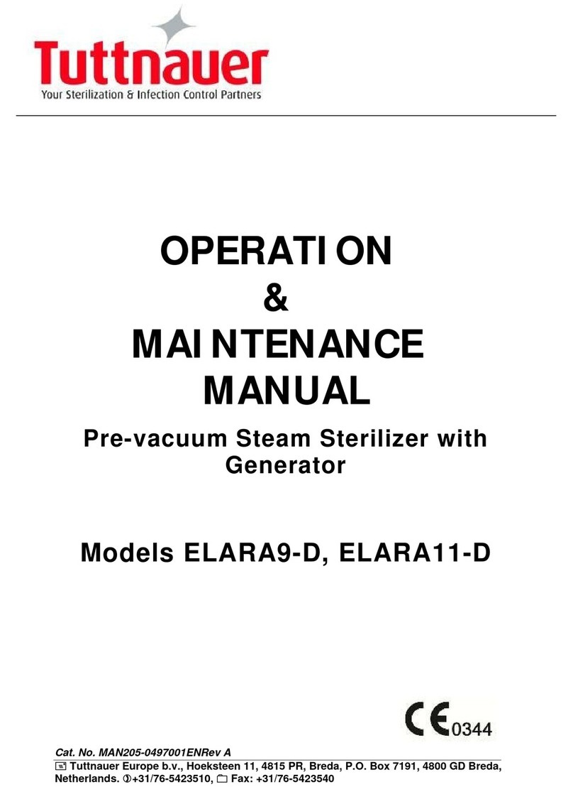
Tuttnauer 5050 Manual

OPERATION
&
MAINTENANCE
MANUAL
Laboratory Vertical Steam Sterilizers
Models 5050 and 5075 ELVCPVG, ELVCPVGBH-D
ELVCPVG-D –Including Pre-Vacuum
ELVCPVGBH-D –Including Bio-Hazard
Cat. No. MAN205-0479000EN Rev A
Tuttnauer Europe b.v., Hoeksteen 11, 4815 PR, Breda, P.O. Box 7191, 4800 GD Breda, Netherlands.
+31/76-5423510, Fax: +31/76-5423540
Tuttnauer U.S.A. Co, Ltd. 25 Power Drive Hauppauge, NY, 11788, USA.
Tel (631) 737 4850, (800) 624 5836, Fax: (631) 737 0720


Page 1 of 85 Pages
TABLE OF CONTENT
PARAGRAPH PAGE NO.
1 GENERAL............................................................................................................5
1. Introduction.................................................................................................5
1.1 Incoming Inspection....................................................................................6
1.2 Warranty......................................................................................................6
1.3 Warranty Statement.....................................................................................7
2 SAFETY INSTRUCTIONS ..................................................................................8
3 TECHNICAL DATA...........................................................................................10
3.1 Stand –by heating mode............................................................................10
3.2 Storage Conditions ....................................................................................10
3.3 Operating Conditions.................................................................................10
3.4 Utilities.......................................................................................................10
3.5 Construction ..............................................................................................11
3.6 Environment Emission Information .........................................................11
3.7 Directives and Standards...........................................................................11
3.8 Electrical Data...........................................................................................12
3.9 Overall Dimensions Models 5050, 5075 EL..............................................13
3.10 Symbol Description....................................................................................14
3.11 Water quality..............................................................................................15
3.12 Safety Features..........................................................................................16
4 CONTROL PANEL ............................................................................................19
4.1 CONTROL PANEL DRAWING................................................................19
4.2 Description and Functions of the Front Panel Keyboard.........................20
4.3 Displayed Error Messages / Symbols.........................................................22
4.4 Displayed operational messages / Symbols................................................22
4.5 Description of Operation ...........................................................................23
4.6 Leakage Test..............................................................................................24
4.7 Exhaust......................................................................................................24
4.8 Drying (PV –pre-vacuum nodel only) ......................................................24
4.9 Vacuum Test Program (PV –pre-vacuum model only)............................24
5 STERILIZATION PROGRAMS.........................................................................25
Program 1: Glass................................................................................................27
Program 2: Plastic..............................................................................................28
Program 3: Liquid A...........................................................................................29
Program 4: Liquid B –Waste.............................................................................30
Program 5: Liquid A –Cooling (ELC –cooling models only)...........................31
Program 6: Liquid B –Waste Cooling (ELC –cooling models only)................32
Program 7: Waste...............................................................................................33
Program 8: Hollow Load....................................................................................34

Page 2 of 85 Pages
Program 9: Vacuum Test (PV, pre-vacuum model only)...................................35
Program 10: Bio Hazard Liquid Cooling (BH, bio-hazard models only)..........36
Program 11: Bio Hazard Liquid (BH, bio-hazard models only)........................37
Program 12: Bio Hazard (BH, bio-hazard models only)....................................38
Program 13: Warm-Up.......................................................................................39
Program 14: Isothermal .....................................................................................40
6 CHECKING AND CHANGING PARAMETERS AND OTHER DATA...........41
6.1 Directories and subdirectories...................................................................41
6.2 Entering the main menu............................................................................41
6.3 System Parameters.....................................................................................43
6.4 History........................................................................................................45
6.5 Maintenance ..............................................................................................47
6.6 Advanced Options......................................................................................51
6.7 Version information...................................................................................54
7 SCREENS...........................................................................................................57
7.1 Screens following a completely successful cycle –"Cycle Ended" ..........57
7.2 Screens following aborted cycles after complete sterilization stage..........58
7.3 Screens following a fail cycle:...................................................................58
8 PRINTER............................................................................................................60
8.1 Printer Output............................................................................................60
8.2 Printer Handling........................................................................................62
8.3 Treating the thermal papers:.....................................................................64
9 PREPARATION BEFORE STERILIZATION..................................................65
9.1 Instruments................................................................................................65
9.2 Liquids .......................................................................................................66
9.3 Tubing........................................................................................................67
9.4 Loading......................................................................................................67
10 OPERATING INSTRUCTIONS ........................................................................68
10.1 Turning on the autoclave ..........................................................................68
10.2 Opening the door .......................................................................................68
10.3 Safety..........................................................................................................69
10.4 Loading......................................................................................................69
10.5 Selecting the Program ...............................................................................69
10.6 Closing the door.........................................................................................69
10.7 Starting cycle .............................................................................................69
10.8 Unloading ..................................................................................................71
10.9 Stopping the process and cancelling the ERROR message.......................71
10.10Start Cycle by Clock mode.........................................................................72
11 SERVICE AND MAINTENANCE INSTRUCTIONS .......................................73
11.1 Preventive and Scheduled Maintenance ...................................................73
11.2 Checking the Safety Valve.........................................................................74

Page 3 of 85 Pages
11.3 Moving the Autoclave................................................................................79
12 TROUBLESHOOTING......................................................................................80
13 BASKETS AND CONTAINERS ........................................................................84
14 SPARE PARTS LIST –5075..............................................................................85
15 ACCESORIES LIST...........................................................................................85

Page 4 of 85 Pages
TABLE OF CONTENT (Cont.)
DRAWINGS PAGE NO.
FRONT VIEW .............................................................................................................17
REAR VIEW................................................................................................................18

Page 5 of 85 Pages
1 GENERAL
1. Introduction
Model 3870 ELVCPVGBH-D is a laboratory sterilizer designed especially
for the sterilization of instruments, liquids, and other materials in hospital
laboratories, medical laboratories (including the medical waste), research
institutes, food laboratories, and pharmaceutical facilities.
The PV (pre-vacuum) models are equipped with a vacuum pump.
The advantages of the pre-vacuum sterilizer in comparison to the regular
gravity displacement steam sterilizer are as follows:
—Removal of air pockets from packs and porous loads and most kinds
of tubes (rubber, plastic etc.) by vacuum at the first stage of the cycle.
—Better steam penetration into the load; resulting in effective
sterilization.
—Better temperature uniformity.
—Better drying of materials with closed doors due to the vacuum
achieved in the chamber at the end of the sterilization cycle.
The autoclave is equipped with A 9Kw generator that produces the steam
required for the sterilization.
A special feature of the autoclave is fast cooling stage for liquids. In this
stage pressure in the chamber is increased by means of compressed air to
compensate the fast decreasing of pressure due to the fast cooling. The fast
cooling shortens the time required for safe handling of bottles.
In BH (bio-hazard) models, a bio-hazard filter installed in the chamber
enables sterilizing bio-hazard load without contaminating the surrounding.
A computerized control unit ensuring a fully automatic sterilization cycle
controls the autoclave.
The temperature and pressure are controlled through sensors placed inside
and outside the media container or bottles.
The sterilizer is fully automatic with a choice of 14 programs, eliminating
any need for operator intervention during a cycle (programs 9-10 are for
vacuum testing only). A computerized control unit enables precise control
and monitoring of physical parameters and clear documentation of the
sterilization cycles.
The autoclave is equipped with a safety valve, which will discharge at an
overpressure of over 2.8 Bar (40 psi), which is located on the chamber
near the pressure switch and the steam pressure gauge. The control system
provides adequate protection, to ensure the safety of personnel and
reliable operation with a minimum of down time.
The sterilizer has multiple built - in safety devices, which provides
adequate protection to ensure the safety of operating personnel.
The printer prints the preset and actual parameters of the cycle
(temperature, time and pressure).
The autoclave is provided with a pressure gauge that is used as guide only.
Should there be a power failure during the operation of the autoclave, the

Page 6 of 85 Pages
pressure gauge indicates to the operator that there is pressure in the
chamber.
A deviation of +1.6% is accepted.
NOTE:
After operating the sterilizer, brown stains might appear on the bottom of
the chamber. These stains are a result of the heating elements that are
located at the lower external part of the chamber. The brown color is a
common phenomenon, can easily be removed, and will not have any effect
on the sterilized goods.
This manual is intended to give the user a general understanding of how
the autoclave works and indicates the best ways to operate and take care of
it in order to obtain optimum results and a trouble-free operation. After
reading this manual, operating the autoclave should be straightforward.
However, since the autoclave is built using high technology sensitive
components, no attempt should be made by the user or any other
unauthorized person to repair or recalibrate it.
Only technical personnel having proper qualifications, holding
technical documentation and adequate test instrumentation are
authorized to undertake repair or service.
1.1 Incoming Inspection
The autoclave should be unpacked and inspected for mechanical damage
upon receipt. Observe packing method and retain packing materials until
the unit has been inspected. Mechanical inspection involves checking for
signs of physical damage such as: scratched panel surfaces, broken knobs,
etc.
If damage is apparent, contact your dealer or point of purchase, so that they
may notify the manufacturer and file a claim with the appropriate carrier.
All Tuttnauer products are carefully inspected prior to shipment and all
reasonable precautions are taken in preparing them for shipment to assure
safe arrival at their destination.
1.2 Warranty
We certify that this instrument is guaranteed to be free from defects in
material and workmanship for one year against faulty components and
assembly with the exception of glassware, lamps and heaters.
The warranty does not include and does not replace routine treatment
and preventive maintenance to be performed according to instructions
in paragraph 9.1 (Preventive and Scheduled Maintenance).
Our obligation is limited to replacing the instrument or parts, after our
examination, if within one year after the date of shipment they prove to be
defective. This warranty does not apply to any instrument that has been
subjected to misuse, neglect, accident or improper installation or
application, nor shall it extend to autoclaves that have been repaired or
altered outside the factory without prior authorization from us.
The Autoclave should not be used in a manner not described in this
manual!

Page 7 of 85 Pages
1.3 Warranty Statement
The warranty registration must be completed and returned to our service
departments; within fourteen (14) days of purchase or the warranty will be
void.
Our Technical Service Depts can be reached at:
Tuttnauer Europe b.v., Hoeksteen 11, 4815 PR, Breda,
P.O. Box 7191, 4800 GD Breda, Netherlands. +31/76-5423510,
Fax: +31/76-5423540, E-mail: [email protected]
Tuttnauer USA Co., Ltd., 25 Power Drive Hauppauge, NY 11788, USA
: (800) 624 5836, (631) 737 4850, Fax: (631) 737 0720
e-mail:[email protected].
Note:If there is any difficulty with this instrument, and the solution is not
covered in this manual, contact our representative or us first. Do not
attempt to service this instrument yourself. Describe the difficulty as
clearly as possible so we may be able to diagnose the problem and provide
a prompt solution.
If the autoclave is equipped with a printer, send along a copy of the last
printout for our inspection. If replacement parts are needed, stipulate the
model and serial number of the machine.
No autoclaves will be accepted for repair without proper authorization
from us. All transportation charges must be paid both ways by the owner.
This warranty will be void if the unit is not purchased from an authorized
full service Tuttnauer dealer.

Page 8 of 85 Pages
2 SAFETY INSTRUCTIONS
The autoclave has unique characteristics. Please read and understand the operation
instructions before first operation of the autoclave. The following issues may
require instructions guidance provided by the manufacturer: how to operate the
autoclave, the door safety mechanism, the dangers involved in circumventing
safety means, how to ensure that the door is closed, and how to select a correct
sterilization program.
Make sure that you know where the main power switch is, where the water cut-off
valve is and where the steam and compressed air disconnection valves are located.
Autoclave maintenance is crucial for the correct and efficient function of the
device. We enclose a log booklet that includes maintenance recommendations,
with every device.
The weekly spore test is part of the preventive maintenance plan, along with the
annual validation of the sterilization processes that ensures appropriate
temperature dispersion within the chamber.
Never use the autoclave to sterilize corrosive products, such as: acids, bases and
phenols, volatile compounds or solutions such ethanol, methanol or chloroform
nor radioactive substances.
1. Never start using a new autoclave or a new steam generator, before the
safety, licensing and authorization department has approved it for use.
2. All autoclave users must receive training in proper usage from an
experienced employee. Every new employee must undergo a training
period under an experienced employee.
3. A written procedure must be established for autoclave operation,
including: daily safety tests, seal inspection and door hinge inspection,
smooth action of the closing mechanism, chamber cleaning, prevention of
clogging and preservation from corrosion, what is permitted and what is
prohibited for sterilization and choosing a sterilization program.
4. Liquids may be sterilized only with the “liquids” program. The container
must be covered but not sealed. Sealed bottles may only be sterilized using
a special program. The bottle must be either Pyrex or a Borosilicate glass
bottle. Verify that the two temperature sensors are located inside two
different bottles to assure that the liquid temperature is 20°C below boiling
temperature for sealed bottles at the end of the cycle.
5. When sterilizing plastic materials, make sure that the item can withstand
sterilization temperature. Plastic that melts in the chamber is liable to
cause a great deal of damage.
6. Individual glass bottles may be placed within an appropriate container that
will be placed on a tray. Never place glass bottles on the floor of the
autoclave. Never fill more than 2/3 of the bottle volume.
7. On closing the autoclave's door, make sure it is properly locked before
activating.
8. Before withdrawing trays and containers, wear heat resistant gloves.
9. Before opening the door, verify that there is no pressure in the chamber
(chamber pressure gauge is located on the autoclave's front panel or door,
depends on the model).
Page 9 of 85 Pages
10. Open the door slowly to allow steam to escape and wait 5 minutes before
you remove the load. When sterilizing liquids, wait 10 minutes.
11. Once a month, ensure that the safety valves are functioning, and once
annually a certified tester must conduct pressure chamber safety tests.
12. Once annually, or more frequently, effective tests must be performed, i.e.,
calibration and validation.
13. Examine the condition of assemblies on a regular basis. Make sure there
are no leaks, breaks, blockages, whistles or strange noises.
14. It is required to conduct maintenance operations as instructed.
15. Immediately notify the person in charge of any deviation or risk for the
proper function of the device.

Page 10 of 85 Pages
3 TECHNICAL DATA
3.1 Stand –by heating mode
The autoclave provides an option of heating the chamber in stand-by mode
between cycles with a very low power in order to reduce total cycle time
(1.6% of the total power only). The autoclave turns off automatically if the
interval between the sterilization cycles is more than 2 hours.
3.2 Storage Conditions
Packed or unpacked, the autoclave shall be retained in indoor
conditions!
3.3 Operating Conditions
The autoclave is intended to work in ‘indoor’ conditions only.
Only autoclavable materials shall be used.
The environment shall not exceed an ambient temperature range of 5ºC
(41ºF)-40ºC (104ºF) and a relative humidity of 85% respectively.
The operation altitude shall not be over 2000 meters (6561 feet)
(ambient pressure shall not be lower than 80 kPa (11.6 psi)).
The autoclave shall not be used in a manner not specified in this
manual!
Do not use the autoclave in the presence of dangerous gases.
Operate the autoclave only in the manner specified in the manual. If
the equipment is used in a manner not specified by the manufacturer,
the protection provided by the equipment may be impaired.
Caution!
Waste water should be brought into the public net in accordance with
the local rules or requirements i.e ONLY NON-HAZARDOUS LIQUIDS
SHALL BE DISPOSED IN PUBLIC SEWAGE!
3.4 Utilities
3.4.1 Electrical utility
Power
Switch box
Recommended
Circuit Breaker
208-220V (3 Ph + Earthing)
No
20A
380-400V(3 Ph + Neutral +
Earthing)
No
16A
Frequency
50/60Hz

Page 11 of 85 Pages
3.4.2 Other utilities
Compressed Air (ELVC only)
1/2" 3-4 Bar (44-58 psi)
Tap water
1/2", 2-3 Bar (29-44 psi)
Mineral free water
1/2", 2-3 Bar (29-44 psi)
Drain
2" Minimum Withstanding temp.
of 80°C (176°F)
Attention:
The electrical net must be protected with a current leakage safety relay.
The electrical network must comply with local rules or regulations.
3.5 Construction
The main parts of the autoclave are made of materials as indicated below:
Chamber and door are made of stainless steel
Trays are made of stainless steel.
Door handle is made of hard plastic material, which is safe to touch
and thermo-insulated.
3.6 Environment Emission Information
1. The peak sound level generated by the autoclave is less than 70 dBa
with background noise of 60 dBa.
2. The total heat per hour transmitted by the autoclave is < 100 W/h for
all models.
3.7 Directives and Standards
Every autoclave meets the provisions of the following Directives and is
constructed in compliance with the following Standards:
3.7.1 Technical Directives
1. Pressure Equipment Directive 97/23/EC.
2. Council Directive for low voltage equipment 73/23/EEC.
3. Electromagnetic Compatibility Requirements Directive
89/336/EC.
3.7.2 Technical Standards
1. AAMI/ANSI ST 8.
2. ASME Code Sec. VIII for Pressure Vessels.
3. Pressure Equipment Directive 97/23/EEC.
4. EN 285:2006 ― Sterilization, Steam sterilizers , Large
sterilizers
5. IEC/UL 61010A-1 ― electrical equipment for laboratory
use; general requirements.
6. IEC 61010-2-040 ― particular requirements for sterilizers
and washer disinfectors used to treat medical materials.
7. ISO 17665 ― 1:2006 Sterilization of health care products
moist heat.

Page 12 of 85 Pages
3.7.3 Quality standards
The manufacturing plant meets the following quality standards:
1. EN ISO 9001:2008–Quality System
2. ISO 13485:2003 –Quality systems –Medical devices.
3.8 Electrical Data
Model
Power
consumption
Supply Voltage
Line
current
Protection against
electrical shock
5075
6 x 1100W
3 Ph, 400V/50Hz
11A
Class I
(IEC 60601-1)
5050
4 x 1100W
3 Ph, 400V/50Hz
11A
Class I
(IEC 60601-1)

Page 13 of 85 Pages
3.9 Overall Dimensions Models 5050, 5075 EL
FRONT VIEW SIDE VIEW
Model
Dimensions
5050
5075
EU units
US units
EU Units
US Units
Overall
dimensions
Height
1090mm
42.9”
1090mm
42.9”
Width
870mm
34.3”
870mm
34.3”
Length
770mm
30.3”
770mm
30.3”
Maximum
dimensions
(door open)
Width
960mm
37.8”
960mm
37.8”
Height
1690mm
66.5”
1690mm
66.5”
Distance
between
supporting
legs
Width
750mm
29.5”
750mm
29.5”
Length
590mm
23.2”
590mm
23.2”
Net weight (kg)
Shipping volume (m3)
Shipping weight (kg)
Max. Allowable
Working pressure
(MAWP)
2.8 bar
40 psi
2.8 bar
40 psi

Page 14 of 85 Pages
Chamber
diameter
500mm
19.7”
500mm
19.7”
Depth
500mm
19.7”
750mm
29.5”
Chamber volume
110 lit.
29.1 US gal
160 lit.
42.3 US gal
Max. Allowable
Working Pressure
(MAWP)
2.76 bar (40 psi)
Load No. counter
Counting from 0 to 3000 and nullifies.
Tray dimensions
W X D
32.0 x 55.0
cm
12.6” x 21.7”
32.0 x 78.0
cm
12.6” x 30.7”
Attention:
A switch or circuit-breaker must be included in the building
installation. This switch or circuit-breaker shall be in close proximity
to the equipment, within easy reach of the operator; and marked as the
disconnecting device for the equipment.
The electrical net must be protected with a current leakage safety
relay.
The electrical network must comply with local rules or regulations.
Verify that there is an easy access to the main power switch, to the
water cut-off valve and to the current leakage safety relay.
Make sure while placing the autoclave, to leave space around the
machine, to give the technician access to service the machine.
All water connections to autoclave must be performed through
"BACK FLOW PREVENTION SYSTEM" only, as per IEC 61770.
3.10 Symbol Description
Caution! Consult accompanying documents
Caution! Hot surface.
Caution! Hot steam.
Protective earth (Ground)
On-Off

Page 15 of 85 Pages
3.11 Water quality
The distilled or mineral by two water systems: to the sterilizer shall be
according the table below. Tap water for the vacuum pump:
Hardness should not exceed 0.7:2 mmol/l S
Pressure should be in the range of 2–5. bar (30–70 psi)
Connection to the network by a ½”onnectioDistilled or Mineral Free
Water:
Distilled or mineral free water for the steam generator.
Connect the distilled water inlet to a distilled or mineral free water supply
source by a ½" pipe.
Pressure should be in the range of 2–5. bar (30–70 psi)
3.11.1 Water for generating steam
The distilled or mineral –free water supplied to the autoclave
should have the physical characteristics and maximum
acceptable level of contaminants indicated in the table below:
Physical Characteristics and Maximum acceptable
contaminants levels in steam for sterlizers
(According to EN 285:2006).
Contaminants
in water
supplied
to generator
Contaminants
in condensate
at steam inlet
to sterilizer
Evaporate residue
≤ 10 mg/l
N/A
Silicate (SiO2
≤ 1 mg/l
≤ 0.1 mg/l
Iron
≤ 0.2mg/l
≤ 0.1mg/l
Cadmium
≤ 0.005 mg/l
≤ 0.005 mg/l
Lead
≤ 0.05 mg/l
≤ 0.05 mg/l
Rest of heavy metals except iron,
cadmium, lead
≤ 0.1 mg/l
≤ 0.1 mg/l
Chloride (Cl)
≤ 2 mg/l
≤ 0.1 mg/l
Phosphate (P2O5)
≤ 0.5 mg/l
≤ 0.1 mg/l
Conductivity (at 25°C)
≤ 5 µs/cm
≤ 3 µs/cm
pH value (degree of acidity)
5 to 7.5
5 to 7
Hardness (Σ ions of alkaline earth)
≤ 0.02 mmol/l
≤ 0.02 mmol/l
Appearance
Colourless, clean, without sediments
Compliance with the above data should be tested in accordance with
acknowledged analytical methods, by an authorized laboratory.

Page 16 of 85 Pages
Attention:
We recommend testing the water quality once a month. The use of
water for autoclaves that do not comply with the table above may
have severe impact on the working life of the sterilizer and can
invalidate the manufacturer’s guarantee.
3.11.2 Reverse Osmosis
A Reverse Osmosis (RO) system may be used to improve the
quality of the water used to generate steam in the autoclave
chamber.
In RO, the water is forced through a semi-penetrable membrane,
which filters out contaminants to a high degree of efficiency. In
deionisation (DI) ions and charged particles are removed either
by electric fields or by ion exchange in resin beds.
Although the RO cannot normally attain the degree of purity
possible with the DI methods, it is more than adequate for the
feed water intended for clean-steam generators.
Moreover the RO has several advantages:
1. RO is cheaper to install and to run than DI.
2. RO removes particulate matter, organic molecules and
pyrogens that DI cannot remove
3. RO water is less corrosive to steel and copper than DI
water.
4. RO maintenance requirements are less demanding than
those of the DI units.
Therefore the use of mineral free water will contribute to better
performance and longer life of the autoclave.
3.12 Safety Features
This autoclave includes built-in safety features such as:
Error message display.
Electronic pressure and temperature measurement.
Safety relief valve to avoid build-up of excessive pressure.
Door switches enabling operation to be started only when the door is
closed.
Water level safety device.
Excess temperature protection.

Page 17 of 85 Pages
FRONT VIEW
No.
Description
1
Autoclave cover
7
Keyboard
2
Door Closing Handle
8
Main switch (under the printer cover)
3
Door Closing Grip
9
Right Service Door Grip
4
Front Leg
10
Service Door
5
Chamber Pressure Gauge
11
Rear Leg
6
Display
4
3
2
1
5
7
6
9
8
11
10

Page 18 of 85 Pages
REAR VIEW
No.
Description
1
Generator Safety Valve
2
Mineral-Free Water Inlet
3
Air Supply Pressure Gauge
4
Air Supply Pressure Regulator
5
Drain
6
Chamber Safety Valve
7
Cavitation
8
Circuit breaker
9
Power Supply
10
Tap Water Inlet
11
Air Inlet
1
3
4
2
5
9
10
11
6
7
8
Other manuals for 5050
4
This manual suits for next models
3
Table of contents
Other Tuttnauer Steriliser manuals