Package
1
2
Warning and Caution
■ If the product does not work properly, please contact your dealer or the
nearest service center. Never attempt to disassemble the camera yourself.
(We shall not be responsible for any problems caused by unauthorized repair
or maintenance.)
■ Do not allow water or liquid intrusion into the camera.
■ In the use of the product, you must be strict compliance with the electrical
safety regulations of the nation and region. When the product is mounted on
wall, the device shall be firmly fixed.
■ Do not use camera beyond specified voltage range.
■ Do not drop the camera or subject it to physical shock.
■ Avoid touching the camera lens.
■ If cleaning is necessary, please use clean cloth to wipe it gently. If the
device will not be used for a long time, please cover the lens cap to protect
the device from dirt.
■ Do not aim the camera at the sun or extra bright place.
■ Do not place the camera in extremely hot, cold (the operating temperature shall
be -30˚C~60˚C), dusty or damp locations, and do not expose it to high
electromagnetic radiation.
■ To avoid heat accumulation, good ventilation is required for operating
environment.
Quick Start Guide
Network Camera
■ Please read this instruction carefully before using the product and
keep it for further reference.
■ All the examples and pictures used here are for reference only.
■ The contents of this manual are subject to change without notice.
Camera Quick start guide CD
Plastic plug × 4
Drill template Screwdriver
4 tapping screws
1 machine screw
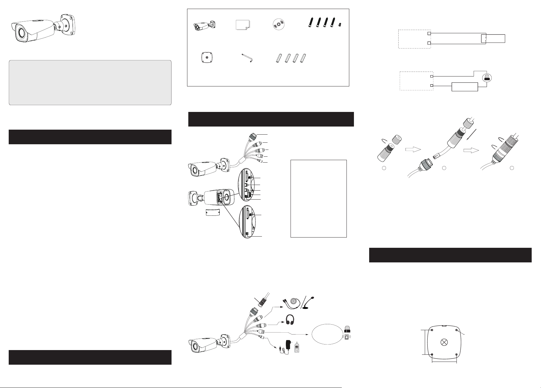
Overview
3
1 Ethernet Connector
2 MIC-Audio Input
3 HP-Audio Output
4 Alarm Output/Input
5 Power Connector *
6 Micro SD Card Slot
7 Zoom +*
8 Zoom -*
9 CVBS output (unavailable)
10 Reset
*
* Only some models support T&W buttons. If your camera doesn’t have these two buttons, please
skip 7 and 8.
If the PoE switch is used to power the camera, DC12V power supply is not required.
Alarm
Power Source
IPC
ALARM1/2-COM
ALARM1/2-OPEN
① Loosen the nut from the main element.
② Run the network cable (without RJ 45 connector) through the both
elements. Then crimp the cable with RJ 45 connector.
③ Connect the cable to the hermetic connector. Then tighten the nut and
the main cover.
23
1
● Connecting Network Cable
Installation
4
● Connecting Alarm Input/Output
Alarm Input
Alarm Ouput
+
+
--
1
3
4
5
2
ALARM
4 3 2 1
6
6
7
8
9
10
10
1--ALM-COM
2--ALM-OPEN
3--ALM-INA
4--ALM-GND
Security cap
DC12V
ALARM
4 3 2 1
Sensor
IPC
ALARM-INA
ALARM-GND
3
4
Please make sure that the wall or ceiling is strong enough to withstand 3
times the weight of the camera. Please install the camera under dry
environment.
① Attach the drill template to the place where you want to fix the camera. Then
drill the screw holes and the cable hole on the wall according to the drill
template.
64.6mm
64.6mm
∅5
(Type A)
(Type B)


