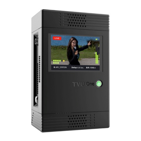
TVU networks One TM1000 v2 Setup guide

TVU OneTM
Set Up and Operating Guide
Model - TM1000 v2
(TVU Version 6.0)
Version 0.7
857 Maude Avenue, Mountain View, CA 94043
Telephone: (650) 969-6732 • FAX: (650) 969-6747
www.tvunetworks.com
Printed in U.S.A.
© 2017 TVU networks Corporation

TVU One TM1000 v2 in V6.0 Set Up and Operating Guide
i
Notices
Copyright © 2017 TVU Networks Corporation. All Rights Reserved. Photographs are the copyright of their
respective owners. Contact TVU Networks Corporation at our Web site: www.tvunetworks.com
Trademark Notices
TVU Networks Corporation Trademark Information
The following are trademarks of TVU Networks Corporation and/or its affiliates in the United States and/or
other countries: TVU®, TVU Networks®,TVU One™, TVU Me™, TVU Grid™, TVU Anywhere™, TVU MLink™, TVU
RPS™, TVU Era™, TVU Dashboard™, TVU Sports™ and TVUPackTM.
Other Trademark Information
The following are trademarks of their respective owners or companies:
TRADEMARK OR REGISTERED
TRADEMARK COMPANY
Verizon®
Verizon Communications, Inc.
AT&T®
AT&T, Inc.
Huawei®
Huawei Technologies Co. Ltd.
Velcro®
Velcro Industries, B.V.
FCC/CE Compliance
Federal Communications Commission (FCC) Regulation of ENG Mobile Systems
The FCC provides specific policies and procedures related to radio frequency (RF) emissions in mobile and port-
able devices. The FCC outlines test requirements and specific test procedures based on the type of device.
These test requirements and procedures can also cover Specific Absorption Rates (SAR) for RF.
The TVU Transmitter device has always conformed to all applicable FCC regulations covering mobile systems for
electronic newsgathering. All required tests for the TVUPack device as outlined in the regulations were per-
formed by a third party testing lab, which issued a certificate of compliance for the TVUPack. The certificate is
applicable to both the FCC and CE. Additionally, the data modems used in TVUPack are commercially available
off-the-shelf brands and have been FCC and carrier certified.
Supporting documentation demonstrating TVU’s compliance with the applicable FCC regulations is available
upon request. Please contact us at +1.650.969.6732 for assistance and questions regarding approved modem
cards for use with TVUPack.

TVU One TM1000 v2 in V6.0 Set Up and Operating Guide
ii
CONTENT
INTRODUCTION...........................................................................................................................................1
ABOUT THIS GUIDE ....................................................................................................................................1
TVU ONE UNIT AND BATTERY SAFETY AND AIRLINE TRAVEL GUIDELINES....................................1
CAUTION.......................................................................................................................................................1
WARNING .....................................................................................................................................................2
IMPORTANT SAFETY INSTRUCTIONS.......................................................................................................2
AC Adapter................................................................................................................................................................3
Use Only TVU Networks Supplied or Authorized Batteries/Chargers........................................................................3
FAA REGULATIONS..........................................................................................................................................3
Size limits ..................................................................................................................................................................3
Quantity limits............................................................................................................................................................4
ADDITIONAL AIRLINE TRAVEL INFORMATION.......................................................................................................4
TVU ONE TRANSMITTER COMPONENTS.................................................................................................5
TVU ONE TM1000 V2TRANSMITTER OPERATIONAL INDICATORS ......................................................................6
TVU ONE TM1000 V2TRANSMITTER ...............................................................................................................6
LCD Display and Power Indicator..............................................................................................................................6
Encoder Side Panel View..........................................................................................................................................7
TVU ONE TM1000 V2 SETUP TIPS.............................................................................................................9
INTERNAL BATTERY..........................................................................................................................................9
Detaching Internal Battery From Encoder..................................................................................................................9
Charging the Internal Battery.....................................................................................................................................9
INSERTING SIM CARDS ....................................................................................................................................9
TVU ONE BAG CONFIGURATION.....................................................................................................................10
TVU ONE TM1000 V2 LCD TOUCH SCREEN.......................................................................................... 11
LCD TOUCHSCREEN DISPLAY ........................................................................................................................11
TVU ONE TM1000 V2 LCD TOUCH SCREEN OPERATIONAL TIPS..................................................... 12
GOING LIVE ...................................................................................................................................................12
PRESENT TRANSMISSION MODES ...................................................................................................................13
MANAGING THE LATENCY ...............................................................................................................................14
SWITCH THE VIDEO ENCODER .........................................................................................................................15
DATA CARD MONITORING ...............................................................................................................................16
TVU ONE TM1000 V2UNIT INFORMATION......................................................................................................17
TURNING OFF THE TM1000 V2.......................................................................................................................17
TRANSMITTER STATUS MONITORING AND CONTROL FROM THE WEB......................................... 18
TVU TRANSMITTER STATUS SCREEN..............................................................................................................18
ETHERNET.....................................................................................................................................................20
WI-FI............................................................................................................................................................21
HOTSPOT ......................................................................................................................................................22
MODEM .........................................................................................................................................................23
UPLOAD ........................................................................................................................................................24
BGAN...........................................................................................................................................................24
BGAN Configuration................................................................................................................................................25
RECEIVER STATUS.........................................................................................................................................27
RETURN VIDEO FEED.....................................................................................................................................28
HDMI VIDEO .................................................................................................................................................29
IP SOURCE....................................................................................................................................................30
RECORDING...................................................................................................................................................31
ALERT...........................................................................................................................................................33
AUDIO CHANNELS..........................................................................................................................................34

TVU One TM1000 v2 in V6.0 Set Up and Operating Guide
iii
UPGRADE FIRMWARE.....................................................................................................................................34
PROGRESS DOWNLOAD..................................................................................................................................35
CONFIGURING SIM CARDS VIA COMMAND TEXT ..............................................................................................36
SETTING ETHERNET IP CONNECTION VIA COMMAND TEXT ...............................................................................38
CONFIGURING A WI-FI CONNECTION VIA COMMAND TEXT ................................................................................39
CONFIGURING THE TVU ONE FOR HOTSPOT (OPTIONAL).................................................................................41
CONTACTING TVU NETWORKS ............................................................................................................. 41
PRODUCT SPECIFICATIONS TVU ONE TRANSMITTER ...................................................................... 42
APPENDIX A: TROUBLESHOOTING VIDEO QUALITY ......................................................................... 44
TROUBLESHOOTING VIDEO QUALITY USING THE STATUS INDICATORS IN NORMAL AND ADVANCED MODES.........44
Quality .....................................................................................................................................................................44
Error rate indicators.................................................................................................................................................44
Line quality indicators..............................................................................................................................................44
APPENDIX B: BIT CENTRAL INTEGRATION (OPTIONAL) ................................................................... 46
APPENDIX C: AUTOSYNC FILE TRANSFER USING WIRELESS HOTSPOT....................................... 47
APPENDIX D: AUTOMATIC INGESTION OF USB MEMORY STICK CONTENT TO TVU ONE ........... 48
APPENDIX E: LOCAL DOWNLOAD OF RECORDED CONTENT TO A USB MEMORY STICK........... 48

TVU One TM1000 v2 in V6.0 Set Up and Operating Guide
Page 1of 49
INTRODUCTION
TVU One represents a tremendous leap forward in mobile newsgathering, delivering the
same industry-leading transmission resiliency and performance, video picture quality
and sub-second latency of a full-size backpack transmitter, but in a more than 90%
smaller and ultra lightweight form factor. With TVU One, broadcasters can fully leverage
the versatility that a small, lightweight IP video transmitter brings in the field without
sacrificing performance, feature functionality or picture quality. To that end, read and
follow the simple instructions contained in this guide and you’ll be broadcasting in no
time!
ABOUT THIS GUIDE
This operational guide provides instruction for setting up the unit and a brief overview
of the available components for this transmitter: TVU One TM1000 v2 that's running
TVU Version 6.0.
Before you begin setting up the TVU Transmitter, we suggest that you identify the de-
vices you intend to use with the unit including: cameras, cables, power sources, mo-
dems and unit accessories. Simply follow the steps contained in this guide to setup your
new TVU.
TVU ONE UNIT AND BATTERY SAFETY AND AIRLINE
TRAVEL GUIDELINES
CAUTION
TO REDUCE THE RISK OF ELECTRIC SHOCK, DO NOT REMOVE COVER (OR BACK).
NO USER-SERVICEABLE PARTS INSIDE. REFER SERVICING TO QUALIFIED SERVICE
PERSONNEL
To reduce the risk of fire or electric shock and annoying interference, use the
recommended accessories only
This apparatus can be operated at a voltage in the range of 12 - 19 V DC. ONLY
USE A TVU NETWORKS SUPPLIED AC ADAPTER WITH THIS UNIT. Important in-
formation regarding the supplied AC adapter:
oThe supplied AC adapter is designed to be used with an input voltage in
the range of 100-240 V AC
oVoltages other than 120 V are not intended for U.S.A. and Canada.
oOperation at a voltage other than 120 V
oAC may require the use of a different AC plug. Please contact either a lo-
cal or foreign TVU Networks authorized service center for assistance in
selecting an alternate AC plug
A coin type battery is installed inside of the unit. Do not store the unit in tem-
peratures over 60 °C (140 °F)

TVU One TM1000 v2 in V6.0 Set Up and Operating Guide
Page 2of 49
Do not leave the unit in an automobile exposed to direct sunlight for a long peri-
od of time with doors and windows closed
Danger of explosion or fire if battery is mistreated
Do not leave the battery in an automobile exposed to direct sunlight for a long
period of time with doors and windows closed
Do not disassemble the battery or dispose of it in fire
Do not store the battery in temperatures over 60°C (140°F)
Use specified charger
Replace battery only with same or specified type
Excessive sound pressure from earphones and headphones can cause hearing
loss
Do not leave the unit in direct contact with the skin for long periods of time
when in use. Low temperature burn injuries may be suffered if the high tempera-
ture parts of this unit are in direct contact with the skin for long periods of time
The mains plug of the power supply cord shall remain readily operable
The AC receptacle (mains socket outlet) shall be installed near the equipment
and shall be easily accessible
To completely disconnect this equipment from the AC mains, disconnect the
mains plug from the AC receptacle
In order to maintain adequate ventilation, do not install or place this unit in a
bookcase, built-in cabinet or any other confined space. To prevent risk of electric
shock or fire hazard due to overheating, ensure that curtains and any other ma-
terials do not obstruct the ventilation
WARNING
To reduce the risk of fire or electric shock, do not expose this equipment to rain
or moisture
To reduce the risk of fire or electric shock, keep this equipment away from all
liquids. Use and store only in locations which are not exposed to the risk of drip-
ping or splashing liquids, and do not place any liquid containers on top of the
equipment
IMPORTANT SAFETY INSTRUCTIONS
1. Read these instructions
2. Keep these instructions
3. Heed all warnings
4. Follow all instructions
5. Do not use this apparatus near water
6. Clean only with dry cloth
7. Do not block any ventilation openings. Install in accordance with the manufac-
turer’s instructions
8. Do not install near any heat sources such as radiators, heat registers, stoves, or
other apparatus (including amplifiers) that produce heat

TVU One TM1000 v2 in V6.0 Set Up and Operating Guide
Page 3of 49
9. Do not defeat the safety purpose of the polarized or grounding-type plug. A po-
larized plug has two blades with one wider than the other. A grounding-type plug
has two blades and a third grounding prong. The wide blade or the third prong
are provided for your safety. If the provided plug does not fit into your outlet,
consult an electrician for replacement of the obsolete outlet
10. Protect the power cord from being walked on or pinched particularly at plugs,
convenience receptacles, and the point where they exit from the apparatus
11. Only use attachments/accessories specified by the manufacturer
12. Use only with the cart, stand, tripod, bracket, or table specified by the manufac-
turer, or sold with the apparatus. When a cart is used, use caution when moving
the cart/apparatus combination to avoid injury from tip-over
13. Unplug this apparatus during lightning storms or when unused for long periods
of time
14. Refer all servicing to qualified service personnel. Servicing is required when the
apparatus has been damaged in any way, such as power-supply cord or plug is
damaged, liquid has been spilled or objects have fallen into the apparatus, the
apparatus has been exposed to rain or moisture, does not operate normally, or
has been dropped
AC Adapter
The rating plate is on the underside of the AC Adapter.
Disconnect the AC mains plug from the AC mains socket when not in use.
Use Only TVU Networks Supplied or Authorized Batteries/Chargers
This device is designed to be used only with TVU Networks supplied batteries. Use only
TVU Networks supplied devices/chargers to charge the supplied batteries. To see a list
of qualified external batteries to use with this device, please contact TVU Networks. Use
of non-qualified batteries with this system may cause damage to the unit or possibly
fire.
FAA Regulations
Rechargeable and non-rechargeable lithium batteries, cell phone batteries, laptop bat-
teries, external batteries, portable rechargers, spare (uninstalled) lithium ion and lithium
metal batteries must be carried in carry-on baggage only. When a carry-on bag is
checked at the gate or at planeside, all spare lithium batteries must be removed from
the bag and kept with the passenger in the aircraft cabin. The battery terminals must be
protected from short circuit.
This covers spare lithium metal and spare rechargeable lithium ion batteries for person-
al electronics such as cameras, cell phones, laptop computers, tablets, watches, calcula-
tors, etc. This also includes external battery chargers (portable rechargers) containing a
lithium ion battery.
Size limits

TVU One TM1000 v2 in V6.0 Set Up and Operating Guide
Page 4of 49
Lithium metal (non-rechargeable) batteries are limited to 2 grams of lithium per battery.
Lithium ion (rechargeable) batteries are limited to a rating of 100 watt hours (Wh) per
battery. These limits allow for nearly all types of lithium batteries used by the average
person in their electronic devices. With airline approval, passengers may also carry up to
two spare larger lithium ion batteries (101-160 watt hours). This size covers the larger
after-market extended-life laptop computer batteries and some larger batteries used in
professional audio/visual equipment.
Quantity limits
None for most batteries –but batteries must be for use by the passenger. Batteries car-
ried for further sale or distribution (vendor samples, etc.) are prohibited. There is a limit
of two spare batteries per person for the larger lithium ion batteries described above
(101-160 watt hours per battery).
Batteries must be protected from damage.
Battery terminals (usually the ends) must be protected from short circuit (i.e., the ter-
minals must not come in contact with other metal). Methods include: leaving the batter-
ies in their retail packaging, covering battery terminals with tape, using a battery case,
using a battery sleeve in a camera bag, or putting them snugly in a plastic bag or protec-
tive pouch.
See the regulation: 49 CFR 175.10(a)(18)
Tip: Newer lithium ion batteries have the watt hour (Wh) rating marked on them. To cal-
culate watt hours, multiply the battery voltage by the Amp hours (Ah). To learn more
about lithium batteries, their restrictions, and how to tell what size they are, go to
http://SafeTravel.dot.gov
Refer to the link below for International Air Transport Association (IATA) regulations and
information regarding airline travel with lithium batteries:
http://www.iata.org/whatwedo/cargo/dgr/Documents/LithiumBattery_PassengerFlyer.j
pg
Additional Airline Travel Information
When traveling, the TM1000 v2's onboard battery should be removed from the unit to
prevent accidental power on. The onboard battery terminals should be protected to
prevent accidental short circuit. Protect the onboard battery terminals by placing them
in a plastic bag or covering the battery terminals with electrical tape.
TVU onboard batteries should always be transported as carry-on baggage. It
should never be transported in the cargo hold.

TVU One TM1000 v2 in V6.0 Set Up and Operating Guide
Page 5of 49
TVU ONE TRANSMITTER COMPONENTS
The TVU One TM1000 v2 transmitter in Figure 1 is comprised of the encoder, internal
battery, and embedded modems.
Figure 1 TVU One TM1000 v2
Standard components for the TVU Transmitter include:
TVU One with H.265 (Includes encoder, internal battery and embedded mo-
dems)
Power supply (AC Adaptor)
5GHz Wi-Fi
5GHz Hotspot
Optional components for the TVU One include:
SIM cards
AC car adapter
Universal adaptor
3 in 1 antenna
Unmanned plane
External modems
Note: If any component is missing, please contact TVU Networks Customer Support at

TVU One TM1000 v2 in V6.0 Set Up and Operating Guide
Page 6of 49
TVU One TM1000 v2 Transmitter Operational Indicators
This section describes each component of the TVU One TM1000 v2 system. Weighing
just 2.2 lbs/1.0 kg, the TM1000 v2 transmitter fits easily in the average person's hand.
TM1000 v2 comes with a multipurpose carrying case for easy use in the field. The unit is
an all-in-one solution that includes an internal battery as well as embedded LTE mo-
dems, H.265 encoder, Wi-Fi and hotspot. Additionally, any Wi-Fi ready wireless camera
can connect wirelessly to TM1000 v2 for untethered HD quality live transmission.
TVU One TM1000 v2 Transmitter
The transmitter is the central component of the TVU One system. The transmitter han-
dles video capturing, video encoding and transmission, modem management and dial-
ing, and status/monitoring of the system.
LCD Display and Power Indicator
Simply press the power button (A) to turn on the TVU One transmitter. The button turns
green when transmitter is powered on (Figure 2). The LCD screen (B) displays configura-
tion and status information for connected modems as well as video input and transmis-
sion. When a video input is connected, an input preview is displayed on the LCD.
Figure 2 TM1000 v2 Front panel LCD display and power button
The LCD screen is a touch screen and users can control various aspects of the transmis-
sion from the LCD preview screen including bitrate and latency. For more information
regarding the functions of the LCD screen, see pg. 11.
A
B

TVU One TM1000 v2 in V6.0 Set Up and Operating Guide
Page 7of 49
Encoder Side Panel View
Figure 3 shows the input / output connections on the TM1000 v2 transmitter and each
input / out is described in Table 1.
Figure 3A Input / Output panel
Label
Connection
TVU One Input / Output Description
A
HDMI IN
Connect valid HDMI input (PAL, NTSC, 720p or 1080i)
B
SDI IN
Connect Valid SDI input (PAL, NTSC, 720p or 1080i)
C
HDMI Out
Displays preview screen on a separate monitor
D
Display Port Out
Displays preview screen on a separate monitor
E
Ethernet input
LAN connection
F
USB Slots (Spare)
Spare USB slot for connection of USB Dongle (for file upload or
system update), USB keyboard, etc.
G
DC Input
Custom DC Power Input
H
Vent
Do not block
Table 1
A
B
C
D
E
F
G
H

TVU One TM1000 v2 in V6.0 Set Up and Operating Guide
Page 8of 49
Figure 3B
Label
Connection
TVU One Input / Output Description
A
Embedded Mo-
dems
SIM card slots 1-6
B
VOIP output
Audio component –3.5 mm mini audio output jack
C
USB Slots
(Spare)
Spare USB slots (including a Type-C slot) for connection of USB Don-
gle (for file upload or system update), USB keyboard, etc
D
Battery Release
Internal battery release latches
Table 2
D
A
B
C
D

TVU One TM1000 v2 in V6.0 Set Up and Operating Guide
Page 9of 49
TVU ONE TM1000 V2SETUP TIPS
Internal Battery
The TVU One TM1000 v2 internal battery is designed to fit within the transmitter unit,
but it can also be easily removed. Complete battery power management for the TVU
One system is available on the LCD touch screen as well as on the Receiver interface.
Detaching Internal Battery From Encoder
Take the following steps to detach the internal battery from the transmitter:
1. On the side of the TM1000 v2 that is opposite the LCD touch screen, users will
find two spring-loaded latches (A)(Figure 4). Push up on the latches to release
the battery from the back of the TM1000 v2.
Figure 4 Battery latch on encoder
Charging the Internal Battery
To charge the internal battery in TVU One, simply connect the provided AC power
adapter to the DC input on the unit and plug in the other end of the adapter into an
electrical outlet. The battery will then begin to charge. Please note that the battery will
charge faster when TVU One is turned off.
Inserting SIM Cards
The TVU One SIM card slots are designed to hold up to six Mini SIM (2FF) cards in six
embedded modems. Take the following steps to insert a SIM card into the embedded
modem slots on the transmitter:
1. The SIM card slots are spring loaded. Simply push in the desired SIM card into
the appropriate slot until it clicks into place.
2. To remove a SIM card, simple push the SIM card in until it clicks and it will pop
back out.
A

TVU One TM1000 v2 in V6.0 Set Up and Operating Guide
Page 10 of 49
TVU One Bag Configuration
The TVU One is designed to be used as a standalone transmitter, or in a bag configura-
tion. The TVU One bag can be worn as a belt pack. Figure 5 is the front of the bag.
Figure 5
The multipurpose carrying case comfortably holds the TVU One while allowing users to
easily access the power button, connections and SIM card slots. The touchscreen LCD
interface on the TVU One can also be used while the unit is in the bag. Additionally, the
mesh sections allow for the essential ventilation of the TVU One unit, so it will not over-
heat in the carrying case.
It has the added feature of an extra pouch on the bottom of the bag that holds one ex-
ternal V-Mount or G-Mount battery. The V-Mount or G-Mount battery plate is accessi-
ble in the bottom pouch of the bag. The external battery can provide additional power
to the TVU One.
The straps on this bag can be configured in a handful of ways, so that users can wear the
TVU One case however they feel is most comfortable for them.

TVU One TM1000 v2 in V6.0 Set Up and Operating Guide
Page 11 of 49
TVU ONE TM1000 V2LCD TOUCH SCREEN
The TVU One TM1000 v2 has an LCD touch screen interface that allows for transmission
control while out in the field. When the TVU One is first turned on, the user will see the
status display screen (Figure 6).
Figure 6
LCD Touchscreen Display
Label
TVU One Transmitter Live Status Screen Description
A
Transmission Status: Displays whether or not the unit is in Live, Online (Standby) or
Preview mode
B
Data Card Status Monitor: Shows the current number and status of all data cards
connected to the unit. The status of data cards connected to the unit will appear as
green, red, orange or gray. Green status indicates that the data card is connected. The
orange status indicates that the connection is trying to be reestablished. Red status
indicates that the data card is not connected. Gray status indicates there is no card
C
Ethernet Connection: Displays the status of the Ethernet connection
D
Receiver Name: Shows the receiver name to which the unit is transmitting
E
Hotspot Connection: Displays the status of the Hotspot connection
F
Wi-Fi Connection: Displays the status of the Wi-Fi connection
G
Latency Status: Displays the current latency of the transmission
H
Bit Rate Status: Displays the current Bit Rate (B/R)
A
B
C
D
B
J
B
I
B
E
B
F
B
G
B
H
B

TVU One TM1000 v2 in V6.0 Set Up and Operating Guide
Page 12 of 49
Label
TVU One Transmitter Live Status Screen Description
I
Audio Input Level Monitor: Dynamically displays the audio input level (DBFS) for the
unit with graphical colors
J
Battery Status: Indicates the status of battery
Table 3
TVU ONE TM1000 V2LCD TOUCH SCREEN OPERATIONAL TIPS
The LCD screen on the TM1000 v2 can be operated with simple taps and swipes of a fin-
ger, much like a smartphone that has a touch screen user interface. When accessed, the
operational functions and status display interfaces available will appear as a pop-up
window or drop down menu that overlays the preview or live video input. Follow these
instructions to access all of the features and functions the TM1000 v2 has to offer
through its LCD touch screen.
Going Live
To go live from the LCD touch screen, simply touch the center of the screen while the
unit is on and connected to a camera source. A pop-up screen will appear (Figure 7). On
this screen, users can select the receiver with which they would like to go live. Once a
receiver is selected, press the red "Go Live" button.
Figure 7
Users will then be instructed to slide a toggle to the right in order to start the live
transmission (Figure 8). To exit from this pop-up screen, simply click the "X" in the top
right corner.

TVU One TM1000 v2 in V6.0 Set Up and Operating Guide
Page 13 of 49
Figure 8
To stop a live transmission, simply tap the middle of the touch screen and a pop-up
screen will appear (Figure 9). A "Stop Live" toggle will appear at the bottom of the page.
Slide the toggle from left to right to stop the live transmission.
Figure 9
Present Transmission Modes
To select a preset transmission mode, users can pull down the drop down menu by slid-
ing their finger from the top of the screen to the bottom (A). The "Modes" interface will
be displayed (Figure 10). Users can choose between these preset transmission modes:
Interview: Bitrate 2048, delay 2 seconds
Normal: Bitrate 5120 delay 4 seconds
Fast Moving: Bitrate 5120, delay 8 seconds
SD: Bitrate 2048, delay 4 seconds
Tapefeed: Bitrate 10240, delay 10 seconds. This mode is optimized for content
with multiple scene changes
Custom: A custom transmission mode set by the receiver

TVU One TM1000 v2 in V6.0 Set Up and Operating Guide
Page 14 of 49
Figure 10
To select a transmission mode, simply scroll through the available options on the touch
screen until the desired transmission mode is highlighted in green. Then click "OK" at
the bottom of the screen (B). To exit from the drop down menu, simply click the "X" in
the top right corner (C).
Managing the Latency
Access that drop down menu by sliding a finger from the top of the screen to the bot-
tom. Swipe from right to left one time to go to the "Latency" interface (A) (Figure 11).
On this page, users can manage the second and sub-second latency. To select the laten-
cy, simple scroll through the seconds and sub-seconds until the desired latency is high-
lighted in green. Then click "OK" on the bottom of the screen (B).
A. Pull down
to reveal
menu
C
B

TVU One TM1000 v2 in V6.0 Set Up and Operating Guide
Page 15 of 49
Figure 11
To exit from the drop down menu, simply click the "X" in the top right corner (C).
Switch the video encoder
Access that drop down menu by sliding a finger from the top of the screen to the bot-
tom. Swipe from right to left two times to view the "Encoder Type" monitoring interface
(Figure 12). On this page, users can switch between these encoder types:
H.265 Interview (A): Use H.265/HEVC algorithm to encode the video with lowest
bitrate.
H.265 Fast Motion (B): Use H.265/HEVC algorithm to encode the video with
higher bitrate to ensure the fast moving frames.
H.264 (C): Use H.264/AVC algorithm to encode the video.
Note: A restart is required to take it effective after you click "OK" (D).
A. Swipe from right
to left to reach the
Latency menu
B
C

TVU One TM1000 v2 in V6.0 Set Up and Operating Guide
Page 16 of 49
Figure 12
To exit from the drop down menu, simply click the "X" in the top right corner (E).
Data card Monitoring
Access that drop down menu by sliding a finger from the top of the screen to the bot-
tom. Swipe from right to left two times to view the "Modem" monitoring interface (Fig-
ure 13). On this page, users can see detailed information for each card within the TVU
One unit as well as the Ethernet (A), Hotspot (B), and Wi-Fi connections (C).
Figure 13
To exit from the drop down menu, simply click the "X" in the top right corner (D).
A
B
C
E
A
B
C
D
D
Table of contents
Other TVU networks Transmitter manuals