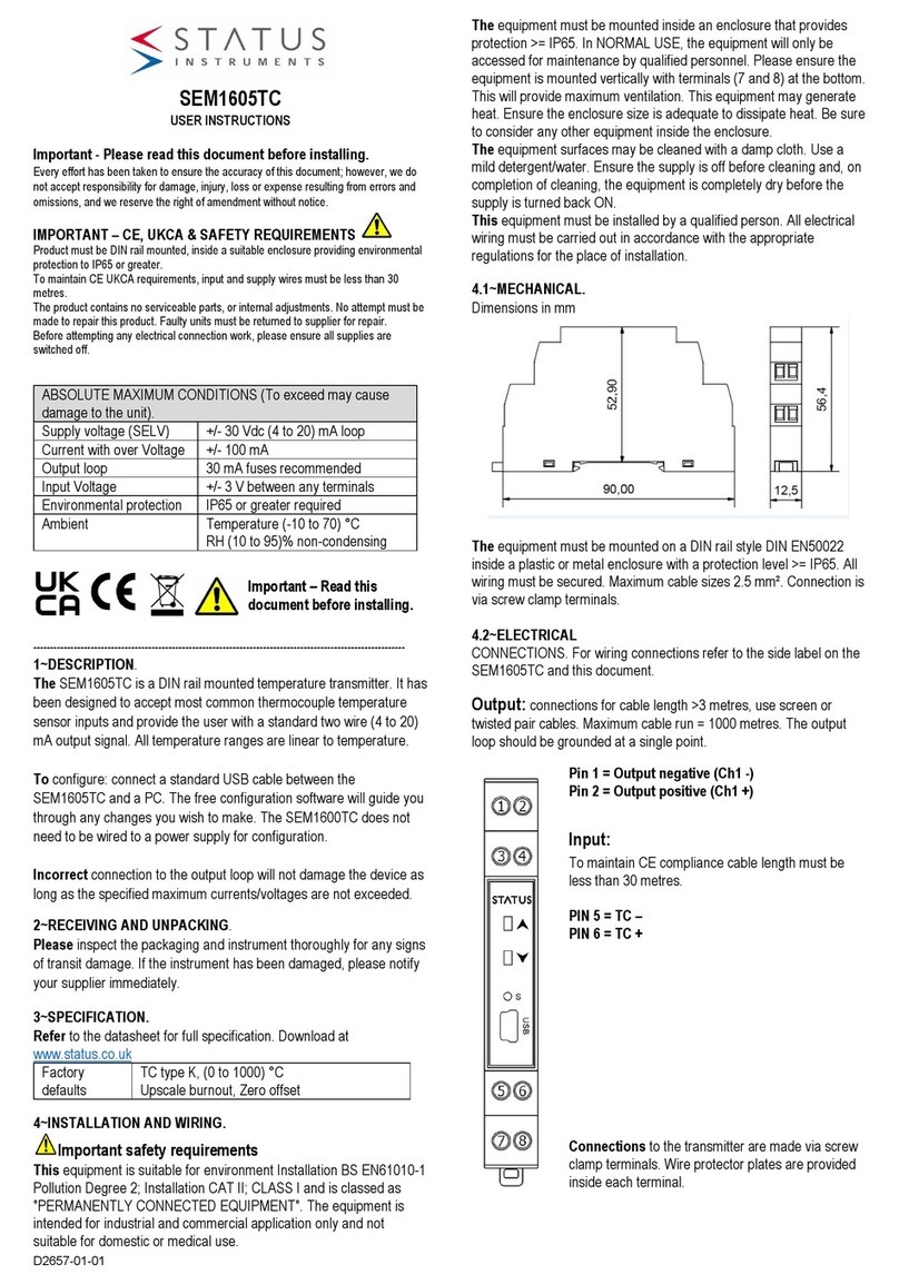
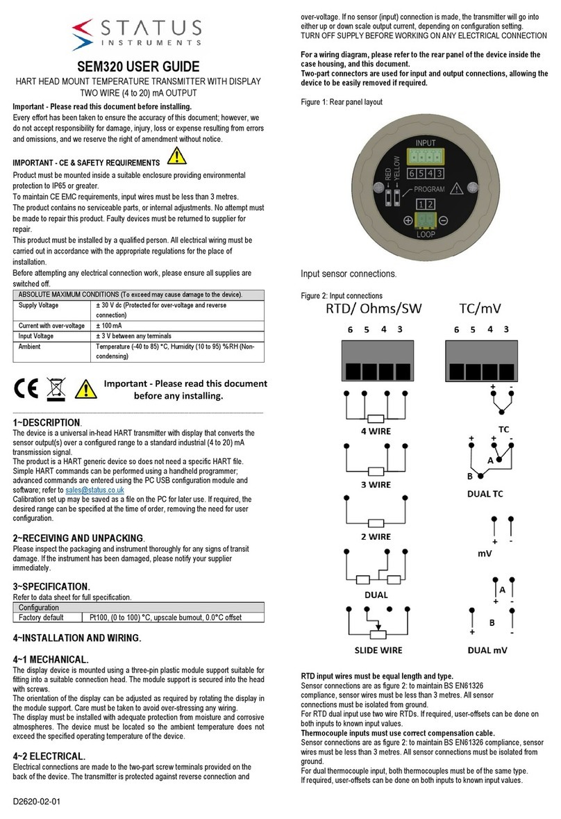
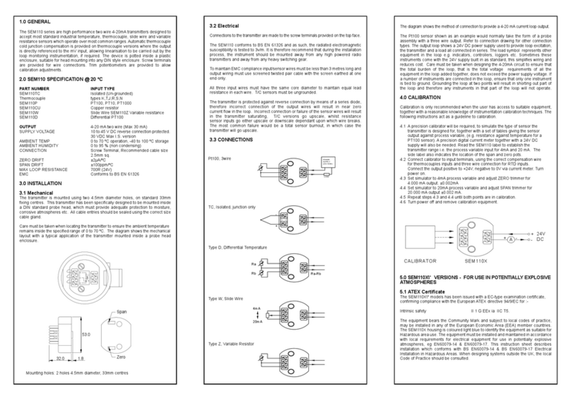
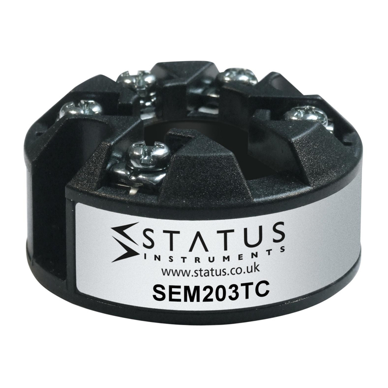
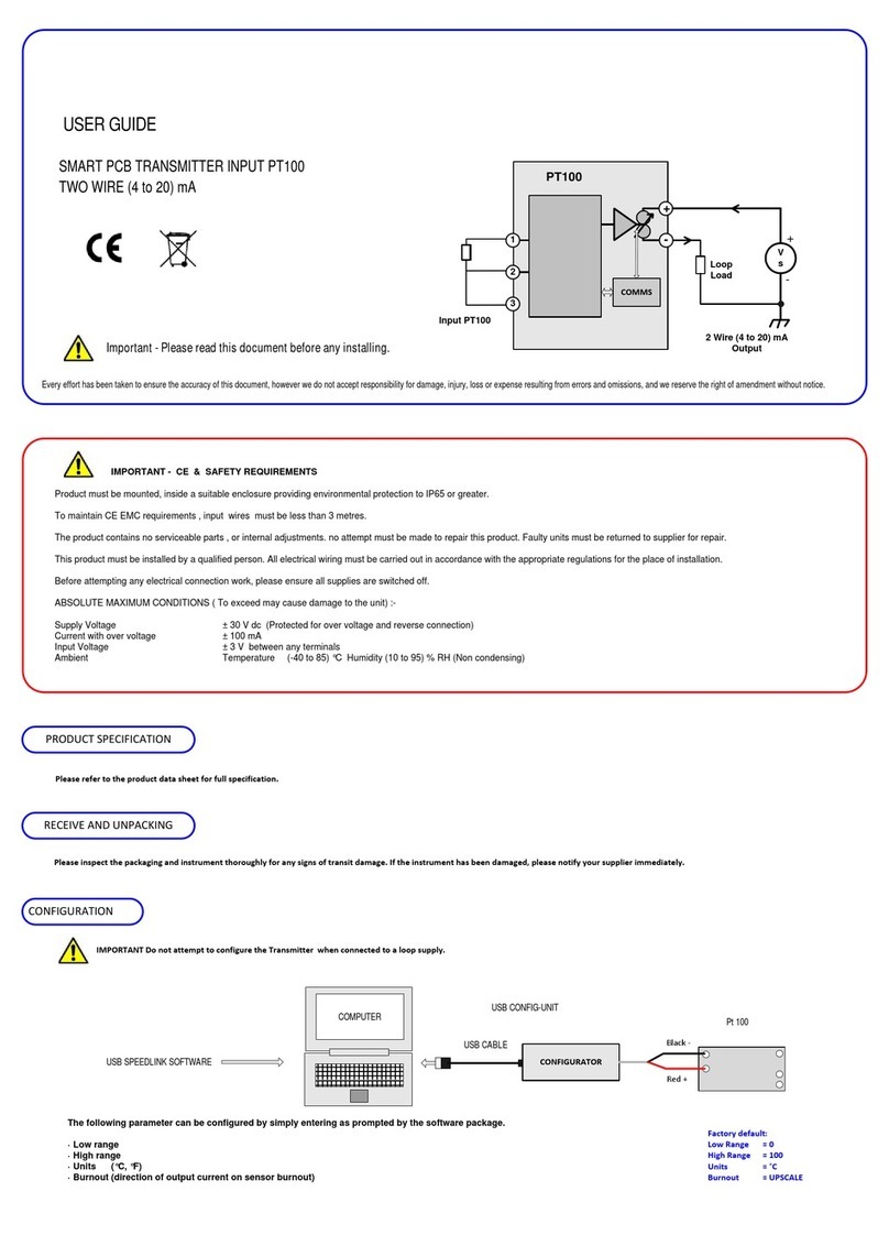
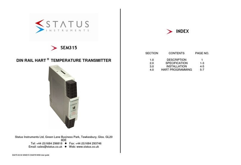
Status SEM320/55 User manual

D2620-01-04 CN5841 SEM320X User guide Page 1of 5
SEM320X USER GUIDE
ATEX / UKEX APPROVED HART HEAD MOUNT TEMPERATURE
TRANSMITTER AND DISPLAY WITH TWO WIRE (4 to 20) mA OUTPUT
Important - Please read this document before installing in particular the ATEX /
UKEX information when applicable to the application.
Every effort has been taken to ensure the accuracy of this document; however, we do
not accept responsibility for damage, injury, loss or expense resulting from errors and
omissions, and we reserve the right of amendment without notice.
IMPORTANT – CE, UKCA & SAFETY REQUIREMENTS.
Product must be mounted inside a suitable enclosure providing environmental
protection to IP64 or greater.
To maintain CE EMC requirements, input wires must be less than 3 metres.
The product contains no serviceable parts, or internal adjustments. No attempt must be
made to repair this product. Faulty devices must be returned to supplier for repair. This
product must be installed by a qualified person. All electrical wiring must be carried out
in accordance with the appropriate regulations for the place of installation. Before
attempting any electrical connection work, please ensure all supplies are switched off.
ABSOLUTE MAXIMUM CONDITIONS: To exceed may cause damage to the
device.
Supply Voltage
± 30 V dc (Protected for over-voltage and reverse connection)
Current with over-voltage
± 100 mA
Input Voltage
± 3 V between any terminals
Ambient
Temperature (-40 to 85) °C, Humidity (10 to 95) % RH (Non-
condensing)
Important – Read this
document before installing.
2503 2776
----------------------------------------------------------------------------------------------------------------------------------------------------------------------------------
1~DESCRIPTION.
The SEM320X is a HART 5 upwards (generic device) compatible universal temperature
transmitter with display. It accepts RTD, Thermocouple, Potentiometer or millivolt input
signals and converts them to the industry standard (4 to 20) mA transmission signal.
Alternatively, HART multidrop mode can be selected, not for ATEX applications.
It is programmed using a communication lead (USBX Config) together with our free
configuration USBSpeedlink software. Standard HART features can also be
programmed using HART communication. The SEM320X has a rotational five-digit
display for the process value and a 5-digit display for messaging, in addition to a bar
graph for % of mA output.
The apparatus is intended for use mounted in a suitable ATEX or IEC Ex approved
enclosure which provides at least IP64 protection.
Sensor types RTD, Thermocouple, Slide wire (resistance). Output two wire (4 to 20) mA
loop, with HART interface.
2~RECEIVING AND UNPACKING.
Please inspect the packaging and instrument thoroughly for any signs of transit
damage. If the instrument has been damaged, please notify your supplier immediately.
3~SPECIFICATION.
Refer to data sheet for full specification.
Configuration
Factory default
Pt100, (0 to 100) °C, upscale burnout, 0.0°C offset
4~SPECIAL CONDITIONS.
4~1 For use to comply with CE, UKCA and safety.
1
The equipment must be installed correctly, providing enviromental
protection of IP64 or greater. Steps must be taken to ensure the
maximum ambient operating range is not exceeded. In particular the
temperature probe surface temperature at the point of entry into the
equipment housing.
2
The maximum recommended sensor wire length is 10 metres. To
maintain full CE EMC requirements for industrial applications, max length
is 3 metres.
3
The device contains no serviceable parts. No attempt must be made to
repair this product. Please return faulty devices to the supplier or
manufacturer.
4
This equipment must be installed by a qualified person. All electrical
wiring must be carried out in accordance with the appropriate regulations
for the place of installation.
4~2 ATEX / UKEX SPECIAL CONDITIONS FOR SAFE USE.
1
a) For gas applications, the SEM320X temperature transmitters must be
mounted in an ATEX/IECEx approved enclosure rated for IP64 and
located in an area where the enclosure will not be subject to impact or
friction
b) For dust applications, the SEM320X temperature transmitters must be
mounted in a suitably ATEX or IECEx certified enclosure appropriate for
the zone of end use.
2
Equipment shall only be configured by means of the USBX configurator
(certificate references ATEX EMT16ATEX0024X, IECEx EMT16.0013X &
CML21UKEX2526X) Connection outside the hazardous area.However, it
can it be config by HART in hazardous area via HART communication.
3
The equipment is mounted in an enclosure with separate IS circuits,
appropriate segregation shall be provided in accordance with
IEC 60079-11 Clause 6.2.1.
4
Only suitable for connection to Thermocouple(s), RTD temperature
sensor(s) or slide wire resistance devices or a simple apparatus. They
shall conform to the requirements for simple apparatus as defined in IEC
60079-11 clause 5.7 and shall meet the dielectric withstanding
requirements of IEC 60079-11 clause 6.3.13.
The insulation must be capable of withstanding an r.m.s a.c. test voltage
of 2U + 1000V, with a minimum of 1500V r.m.s., where U is the sum of
the voltages of the intrinsically safe and the non-intrinsically safe circuit.
5
The ambient temperature range of the enclosure will limit the permitted
ambient range of the overall equipment. Refer to enclosure certification.
5~ATEX / UKEX INSTRUCTIONS.
User instruction for SEM320X electrical apparatus when used in a
hazardous area. Important: Read and understand this section before any
installation.
For safe installation of the SEM320X in hazardous areas the following instructions must
be observed. The device must be installed by competent personnel, who are familiar
with national and international laws, directives and standards that apply to their region.
For installation in European Economic Area (EEA) users in member countries must
follow requirements for electrical equipment for use in potentially explosive
atmospheres, e.g. EN60079-11 & EN IEC60079-0. This instruction sheet describes
installation, which conforms with BS EN60079-14 & BS EN60079-17. Important -
Attention must be paid to the section titled, ATEX / UKEX SPECIAL CONDITIONS FOR
SAFE USE. Failure to comply to this requirement will result in an unsafe system. The
SEM320X has been issued with a certificate, confirming compliance with European
ATEX directive 2014/34/EU, and SI2016 No.1107 for the following specification:
Product Information.
Area Classification
Gases Dusts Zone Criteria for Application Atmosphere
Zone 0
Zone 20
Present continuously or for long periods
(> 1000 hours per annum)
Zone 1
Zone 21
Likely to occur in normal operation occasionally
(> 10 to < 1000 hours per annum)
Zone 2
Zone 22
Unlikely to occur in normal operation
(< 10 hours per annum)
Product label.
Certificate Label.
Working parameters.
Terminals + / -
Ui = 30 Vdc
Ii = 100 mA
Pi = 750 mW
Li = 0
Uo = -
Ci = 0
Io = -
Po = -

D2620-01-04 CN5841 SEM320X User guide Page 2of 5
6~INSTALLATION.
6~1 MECHANICAL.
The display device is mounted using a three-pin plastic module support for fitting into a
suitable connection head. The module support is secured into the head with screws.
The orientation of the display can be adjusted as required by rotating the display in the
module support. Care must be taken to avoid over-stressing any wiring.
The display must be installed with adequate protection from moisture and corrosive
atmospheres. The device must be located so the ambient temperature does not exceed
the specified operating temperature of the device.
The SEM320X module is mounted using two or three holes, with various fixing centres
and will fit a suitable ATEX /IEC Ex approved termination head. The SEM320X must be
installed with adequate protection from moisture and corrosive atmospheres. Refer to
"special conditions for safe use" section of this user guide for information on enclosure
IP rating.
Care must be taken to ensure the SEM320X is located such that the ambient
temperature does not exceed the specified operating temperature as specified in the
"ABSOLUTE MAXIMUM CONDITIONS" table.
Mount the SEM320X into the approved housing as shown below.
SEM320X Module dimensions.
SEM320X Mounting template, showing fixing points to approved
housing.
6~2 ELECTRICAL.
REFER TO ATEX/UKEX SPECIAL CONDITIONS FOR SAFE USE
(See 4~2).
Sensor
Hazardous Area Non Hazardous Area
EX EX
Bar rier
SEM320X
CE II 1 GD
Ex ia IIC T4 Ga
Ex ia 20 T135 °C Da
Tamb = -40 °C to 85 °C
DC Supply
Earth
Ui = 30V
Ii = 100mA
Pi = 750mW
Li = 0
Ci = 0
1000.0°C
Sensor wires must be isolated from earth, breakdown voltage 500 V dc
Electrical connections are made to the two-part screw terminals provided on the back of
the device. The transmitter is protected against reverse connection and over-voltage. If
no sensor (input) connection is made, the transmitter will go into either up or down
scale output current, depending on configuration setting.
TURN OFF SUPPLY BEFORE WORKING ON ANY ELECTRICAL CONNECTION.
For a wiring diagram, please refer to the rear panel of the device inside the case
housing, and this document.
Two-part connectors are used for input and output connections, allowing the
device to be easily removed if required.
Figure 1: Rear panel layout.

D2620-01-04 CN5841 SEM320X User guide Page 3of 5
6~2 ELECTRICAL (Continued).
Input sensor connections.
Figure 2: Input connections.
RTD input wires must be equal length and type.
Sensor connections are as figure 2: to maintain BS EN61326
compliance, sensor wires must be less than 3 metres. All sensor
connections must be isolated from ground.
For RTD dual input use two wire RTDs. If required, user-offsets can be done on both
inputs to known input values.
Thermocouple inputs must use correct compensation cable.
Sensor connections are as figure 2: to maintain BS EN61326 compliance, sensor wires
must be less than 3 metres. All sensor connections must be isolated from ground.
For dual thermocouple input, both thermocouples must be of the same type.
If required, user-offsets can be done on both inputs to known input values.
(4 to 20) mA Loop connections.
Ensure all other aspects of the installation comply with the requirements of this document.
To maintain CE compliance, the (4 to 20) mA current loop must be tied to a local earth at
one point; this is normally at the power supply.
Use twisted pair or screened cables for cable lengths greater than 3 metres. Maximum
cable length 1000 metres.
.
7~USER CONFIGURATION.
IMPORTANT.
READ COMPLETE SECTION BEFORE ATTEMPTING CONFIGURATION.
WARNING.
For configuring or reading live data if using a grounded input or output, it is important
not to connect the programming USB lead to a mains powered computer. It is possible
to damage the instrument if connected in this way.
To avoid damage, use one of the following methods:
•Disconnect the input and output connectors before configuration, reconnect the
connectors after configuration.
•Use a laptop-type computer running from its battery power supply, not connected
to a mains supply. This is recommended for reading live device data or offsetting a
device if already installed in the field.
•Use an approved USB isolator (USBX Config) between the computer and the
device, see supplier for details.
DISPLAY: The display provides five 7-segment characters for display of value and 5
14-segment characters for messages, together with a 10-segment bar graph, % of
output signal display and five icons. The display can operate in an ambient temperature
range of (-20 to 85) °C, but at temperatures lower than -5 °C (due to the slower LCD
speed) scrolled messaging is not practical. The display’s high contrast offers clear
readouts at low as well as high ambient light and direct sunlight.
Figure 3: Display layout.
1. Indicated HART communications
2. Main numeric value display
3. Signal out-of-range warning icon
4. Bar graph of output
5. % of output
6. Bespoke °C and °F temperature indication devices (mA not used)
display.
7. % Message/additional units display
7~1 USBSpeedLink USER CONFIGURATION.
A USBX configuration module is required for connecting the device to the PC. Refer to
your supplier for details.
The device can be configured whilst connected and powered but a portable battery
powered computer must be used to avoid the effects of ground loops if the (4 to20) mA
loop is grounded. This may cause damage to the display device.
Figure 4: Configuration connection.
Configuration must take place in the non- hazadous area with the approved
USBX Config module.
Configuration steps.
Configuration steps must be taken in the non-hazardous areas.
1
Install the software and connect the approved USB configuration module to the
PC.
2
Remove the SEM320X module from the approved housing
3
Remove the rear panel cover held by two screws (see figure 1)
4
Connect the approved configuration module to the device (observe
orientation).
5
Select the correct programming page in the software.
6
Read the device configuration into the software.
7
Re-configure or adjust configuration options as required.
8
Send the new configuration to the device.
Configuration options in USBSpeedLink software.
Sensor tab.
Input type
RTD (type, No. of wires), T/C (type), Ohms, Slide-wire, mV
Single input, dual input (with maths).
Sensor offset
In engineering devices, can be entered for probe/system
correction
Burn out
Any value in input devices to control device behaviour on
input fail
Sensor pre-set
An internal “simulated” value can be applied to the input of
the device for diagnostics

D2620-01-04 CN5841 SEM320X User guide Page 4of 5
7~1 USBSpeedLink USER CONFIGURATION (continued).
Sensor tab.
Process display scaling tab.
Mode Off
Normal use for °C temperature inputs
Mode Scale
Select for °F, process and dual inputs
Mode Profile
Gives 22-segment user-linearisation tool for custom
input to output relationship. Can be used to apply
probe corrections at up to 22 points.
Display decimal place
Used to set the required number for the display
mA output tab.
Damping
Seconds to reach 76% of final value
Low mA
Engineering value to give 4 mA output
High mA
Engineering value to give 20 mA output
Fixed loop
The device can be set to give a pre-set mA output. The
device will return to normal operation after a power
reset, for diagnostics.
Current limits
Can be used to set the minimum and maximum current
values the device can output. Useful for defining burnout
condition.
Namur 43 standard
Burnout control, on or off
Display messages tab.
Range
Use to set up to 6 defined temperature/process bands
that can have fixed or custom messages assigned to
them.
The display will show the messages in turn, with the
input value, when within the selected band.
Message
Define up to 6 custom messages that can be displayed
when the input value is within pre-set bands
MsgA, MsgB
Sets which messages are displayed for each band
Bar and %
Selects whether to show the % of input range bar and
the % of input range value on the screen
Diagnostic tab.
Operation data
Will display:
Maximum and minimum values since last reset
Operational time from manufacture
Operational time from calibration
Calibration date
Cal cert number
Free type field saved to the device
Calibrated by
Free type field saved to the device
Save transducer
Will save the configuration manifest to a text file on the
PC
HART data tab.
Tag number
HART specified; free type field saved to the device
Date
HART specified; saved to the device
Description
HART specified; free type field saved to the device
Message
HART specified; free type field saved to the device
Final Assembly
HART specified; number saved to the device
Long tag
HART specified; free type field saved to the device
Transducer
number
HART specified; number saved to the device
Write protect
HART write protect: On, Off
Read HART.
Transducer
ID
Configuration
counter
Number of changes made via HART communications
HART information tab.
HART info flags
On, Off, see info tab screen image
HART information flags tab.
Live data display
With a device connected to the configuration module, the software can display some
live data readings. The sections to the right-hand side and the bottom of the screen are
used.
Live data reading.
Sensor A
Input value
Sensor B
Input value
Pre-process
Pre-maths input value
Process variable
Post-maths input value
Loop output %
Loop output as a % of range
Loop mA
Loop output in mA
Cold junction
Temperature of the cold junction
Sensor wire
Error detection for input wiring
Loop
Error detection for loop wiring
7~2 HART USER CONFIGURATION.
The SEM320X has HART communications. The SEM320X is a generic HART device.
For a list of implemented HART commands please refer to the data sheet.
Connection is as shown below. A suitable load resister (250 Ohm) must be used in the
loop.
Figure 5: Connection arrangement for HART communications (non-hazardous
area).
Note: The configuration setup shown above is performed in the non-hazardous area.
Configuration with the SEM320X in the hazardous area can be performed:
If
~The HART handheld communicator is approved for use in the hazardous area.
Or
~The HART handheld communicator is in the safe area connected to the SEM320X via
an approved power supply or barrier.
For more information on the HART protocol, refer to the Fieldcomm group website
https://fieldcommgroup.org
For more information on the SEM320 range refer to www.status.co.uk
Status Instruments Ltd, Status Business Park, Gannaway Lane, Tewkesbury,
Gloucestershire, UK, GL20 8FD
Web Page: www.status.co.uk,
Technical Support: support@status.co.uk

D2620-01-04 CN5841 SEM320X User guide Page 5of 5
Tel: +44 (0) 1684 296818, Fax: +44 (0) 1684 293746
This manual suits for next models
2
Table of contents
Other Status Transmitter manuals