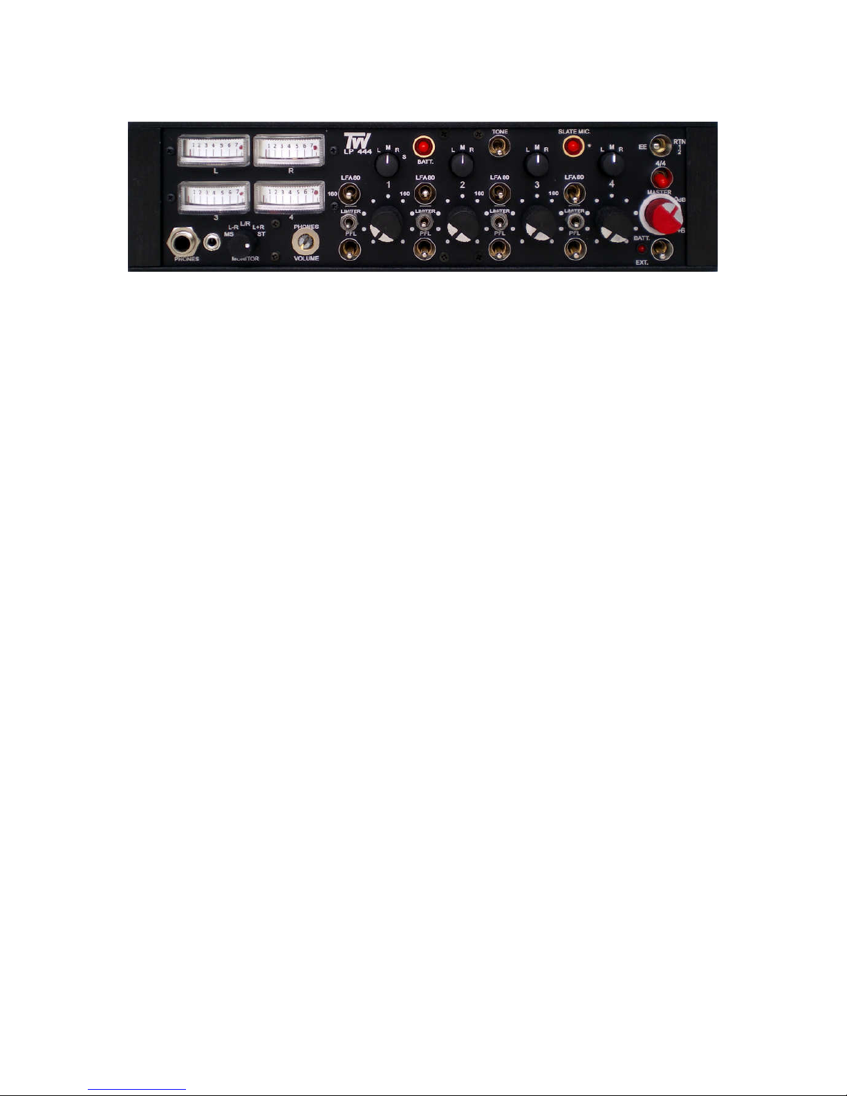
TW Electronic Components LP444 User manual

ELECTRONIC COMPONENTS
LP444
USER MANUAL
TW LP444 is a compact portable 4 in / 2 out and switchable
4 in / 4 out unit designed for four-track recorder or camera.

LEFT SIDE PANEL
Balanced channel inputs – four electronically balanced circuits (transformer balanced is optional)
in phase with one another. XLR connectors should be wired as pin1 ground, pin2 +phase signal and
pin3 –phase signal.
Microphone powering selector switches – The input sensitivity in position D is DYN 200 = 0.2 mV
and no power. Selected 48, 12, T, mic powering, 10 dB of attenuation is automatically introduced,
considering the sensitivity of condenser mics.
Phase reverse switches – Intended to compensate for a phase error due to wiring or mic
placement.
Phantom on / off switch – The current consumption of the phantom power supply is 13 mA.
Phantom power supply may be switched off (only if using dynamic, wireless of T powering mics) to
increase the lifelength of the internal batteries between two chargings.
Attenuation switches – The gain of the mic preamplifiers may be decreased by –10 dB in position
D. In positions 48, 12 and T the attenuation is –13 dB.
Mic / line level switches – Selects mic or line to add –60 dB attenuation before the mic
preamplifiers.
Optional NP1 Battery Holder – The switched mixer supply is derived either from the internal AA
batteries or from NP1 battery depending on the position of the panel side switch.

FRONT PANEL
4 / 4 switch – The TW LP44 mixer works in stereo mode when this switch is turned down. Turned to
4 / 4 position, channel 1 Pan switched in L, channel 2 in R, the four inputs can be controlled
independently by the channel faders to the four outputs.
Modulometers – Continuous lighting, peak reading, BBC 1-7, dB or VU scaling, built-in red LEDs
indicate when the gain reduction is occurring with the limiters switched on.
6.3 and 3.5 mm phone jacks
Monitor selector switch – ST stereo. L+R sum signals, phase check, MS stereo equivalent Left. L–
R difference signals MS stereo equivalent Right. MS matrix, MS stereo equivalent. R right channel. L
left channel. Channels L and 3, channels R and 4 are linked for the monitor circuit in 4 / 4 mode.
Phones volume control – Output voltage into 50 Ωadjustable from 20 to 500 mV.
Limiters on / off switches – The four individual limiters have fast attack time (less than 1 msec) and
a slow release time to smooth operation. Two red LEDs are built in the meters to indicate – depending
on meter selector switch – when the limiters are selected and gain reduction is occurring. Threshold is
internally set to +6 dBu at the balanced output. To adjust the limiter threshold for a value different from
the supplied +6 dBu, see page ADJUSTEMENT POINTS.
Battery check pushbutton – R meter shows the battery status 6/full 5/power LED starts to blinking
and after the battery gets empty.
Reference generator switch – 1 kHz sine wave signal is fed to all four outputs and the level can be
controlled at L and R outputs by the Master control but channel 3 and 4 outputs are internally set to
0 dB.
Slate microphone – It can be used either for identifying recorded segments or as an emergency
field microphone.
Low-cut filter switches – Low frequency attenuation is 14 dB / octave at 100 Hz.
Pan switches – Assign selected input signal to Left or Right output. In M position, equal amount of
signal is sent to Left and Right outputs. The S position of Pan switch 1 assigns Channels 1–2 as a
stereo pair controlled by Channel 1 Fader.
Channel gain controls
Pre-Fade Listen pushbuttons – Each channel can be checked by monitoring. Output audio signal
is not interrupted when the PFL pushbutton is activated.

EE / RTN12 switch – A two-position switch selects the direct outputs from the mixer or the return 1
and 2 as a signal source for the monitoring.
Master – The fader sets the gain of both Left and Right legs and has +6 dB of gain in hand with the
nominal 0 dB gain position marked.
PWR LED – A red LED lights to indicate power is on, and blinking when the battery is too low.
Power switch – In position EXT the mixer will be powered by an external DC supply and in BATT by
the internal batteries. Batteries should be recharged with the switch in EXT position.

RIGHT SIDE PANEL
Balanced outputs – The four main outputs are via transformer balanced XLR connectors. Left and
Right outputs are linked a Hirose 10pin multiway connector to facilitate rapid connection of outputs
and monitor returns. The line level is set on 600 Ωat 0 dBu and +4 dBu for VU metered mixers. The
Hirose 10pin connector is wired as follows:
pin 1. +LEFT output pin 5. RIGHT return
pin 2. –LEFT output pin 6. N / C
pin 3. +RIGHT output pin 7. LEFT return
pin 4. –RIGHT output pin 8. N / C
pins 9., 10. GROUND
Unbalanced Post Fader outputs – A TA5M 5pin connector carries four unbalanced output signals
– at a level 3 dB lower than balanced outputs – to feed a recorder. The connector is wired as follows:
pin1-CH1 out pin2-CH2 out pin3-CH3 out pin4-CH4 out pin5-GROUND
Direct Channel Pre-Fader Outputs – via a TA5M connector, that is wired as follows:
pin1-CH1 out pin2-CH2 out pin3-CH3 out pin4-CH4 out pin5-GROUND
Line / mic level switches – The line level at XLR and Hirose connectors can be attenuated by
50 dB to provide the microphone level.
3.5 mm stereo monitor input jack
Video assist – A mono output formed by summing the Left, Right, Channel 3 and Channel 4 output
channels is also available on a TA3M connector. It is an unbalanced signal at 3 dB below the level of
unbalanced output. The connector is wired as follows:
pin1. GROUND pin3. SIGNAL
Return 1 or 2 selector switch – In position RTN1 the 3.5 jack and Hirose returns are chosen for
monitor, switched to RTN2 the returns of RTN2 3.5 jack will be fitted by the monitoring circuits.
Power supply –The DC power stabiliser of TW mixer has built-in Poly-Fuse to protect the unit. If a
problem occurs that trips this fuse, it will reset after the power supply is disconnected for about 15
seconds. The mixer may be powered by 12 pieces internal AA size rechargeable batteries or an
external DC supply 12-24 Vdc. Fully charged batteries will typically power the mixer for 8 hours at
continuous use. The external XLR 4pin connector is wired as follows:
pin 1., 2. GROUND pin 3. Battery Charge pin 4. External 12-24 Vdc

ADJUSTMENT POINTS
Gain and modulometer adjustment – Connect an AC voltmeter to the Left balanced line output.
Set channel 1 pan switch to L position, turn channel 1 fader fully clockwise, set Master at marked 0 dB
and switch LFA off. Connect an audio generator 1 kHz 0 dBm attenuator –80 dB to Mic 1 Input and
adjust TRIM
A1
to obtain 0 dBu (+4 dBu on VU metered mixers) at the Left balanced output. Then
adjust TRIM
M1
on Modulometer amplifier board to obtain 0 dB on the Left meter. Cut off the input
signal and switch on the Reference Generator . Adjust TRIM
RG
on Ref. Gen amplifier board to obtain
0 dB at the Left meter. Repeat it for Right output and Right meter, that turn up 4 / 4 switch and put
meter selector switch to 3–4 and repeat the setting for Channel 3 and Channel 4 outputs.
Limiter threshold adjustment – Connect an AC voltmeter to the Left balanced line output. Apply a
1 kHz signal until the AC voltmeter reading is at the level desired with limiter switched off. Move the
limiter switch in position LIMITER and adjust TRIM
L1
until the level drops 0.5 dB. Repeat it for Right
output and Right meter then turn up 4 / 4 switch and put Meter selector switch to 3–4 and repeat the
setting for Channel 3 and Channel 4 outputs.

2
3
1
ATTPPS
TMIC
PRE
AMP LFA
PFL
PAN
SWITCH
3
1
2
AMP PFL
LFAPPS
T
ATT PRE
MIC
SWITCH
PAN
3
1
2
AMP PFL
LFAPPS
T
ATT PRE
MIC
SWITCH
PAN
3
1
2
AMP PFL
LFAPPS
T
ATT PRE
MIC
SWITCH
PAN PAN
PAN
L
MASTER
L CHANNEL
R CHANNEL
METER
DRIVER
XLR
R
OUT
XLR
L
OUT
RTN
1
2
RTN
1
2
EE
MONITOR
SELECTOR
MS
MATRIX
P
F
L
L
PHONES
R
PHONES
VOLUME
P
H
O
N
E
S
6.3 3.5
3 2
4 1
DC
BATT
EXT
10 Vdc
VOLTAGE
STABILIZER
BATTERY
PACK
R
3 CHANNEL
4 CHANNEL
L R
4 / 2 4 / 4
L / R 3 / 4
ATT
ATT
HI LO
ATT
ATT
HI LO
HIROSE
10
RTN2
3.5
JACK
VIDEO
XLR
3
OUT
XLR
4
OUT
TW LP44
Schematic Diagram
TA5F
UNBAL.
OUT
RTN1
3.5
JACK
CH1
CH2
CH3
CH4
OUT
DIR.
OUT
DIR.
OUT
DIR.
OUT
DIR.
TA5F
DIRECT
OUT
1
2
3
4

SPECIFICATIONS
Inputs
Microphone: four balanced XLR female
Sensitivity: –75 dBu
Maximum input level: –20 dBu
Microphone power: 48 V, 12 V, T (DIN AB)
Line attenuation: adds 60 dB attenuation before the mic preamp.
Signal to Noise ratio: > 65 dB, Equivalent Input Noise: –125 dBu
Frequency response: 20 Hz - 20 kHz ±2 dB
Harmonic distortion: less than 0.2 %
Low-cut filter: 80 / 100 Hz / 14 dB octave
Crosstalk isolation, channel to channel: < –65 dB
Outputs
Line: transformer balanced XLR
Line level on 600 Ω0 dB on the modulometer: +6 dBu
4 on the 1–7 scaling: 0 dBu
0 Vu on the VU scaling: +4 dBu
Unbalanced line and monitor returns
Maximum output level: +18 dBu
Internal power: battery
External power: 11–25 Vdc
Power consumption: 90 mA
Dimensions: 255 × 165 × 65 mm (10 × 6.5 × 2.6 in)
Weight: 2 kg (4.2 lbs)
ELECTRONIC COMPONENTS
Kaptárkőu. 11. phone.: +36 1 783 7282
Budapest H-1118 mobil: +3620 526 9843
HUNGARY e-mail: twelco@upcmail.hu
www.twelco.hu
Table of contents
Other TW Electronic Components Mixer manuals
Popular Mixer manuals by other brands

la Minerva
la Minerva C/E MM30-05 operating instructions

Varimixer
Varimixer AR100 VL-1L operating instructions

JB-Lighting
JB-Lighting LICON 1X user manual

Meec tools
Meec tools 004870 Translation of the original operating instructions

Black Diamond Equipment
Black Diamond Equipment BDPM-20 instruction manual

Aztech
Aztech ASX6600 user manual