TWK Elektronik CRD R C2Z01 Series User manual

CRD encoder as a subscriber in the PROFIBUS-DP
Accompanying data sheet: CRD 10534
User manual no.: CRD 10617 FE
Datum: 10.07.2012
Heinrichstrasse 85 Postbox 10 50 63 Fax +49 211 637705 www.twk.de
User manual
Certificate Certificate
Z00358 Z00359

Date: 10.07.2012 Page 2 of 28 user manual no. CRD 10617 FE
COPYRIGHT: The Operating Instructions CRD 10617
is owned by TWK-ELEKTRONIK GMBH and is
protected by copyright laws and international treaty provisions.
© 2012 by TWK-ELEKTRONIK GMBH
POB 10 50 63 ■ 40041 Düsseldorf ■ Germany
Tel. +49/211/63 20 67 ■ Fax +49/211/63 77 05

Date: 10.07.2012 Page 3 of 28 user manual no. CRD 10617 FE
Structure
1. Safety instructions ............................................................................................................. 5
1.1 Scope of validity...........................................................................................................................5
1.2 Documentation.............................................................................................................................5
1.3 Proper use ...................................................................................................................................5
1.4 Commissioning ............................................................................................................................5
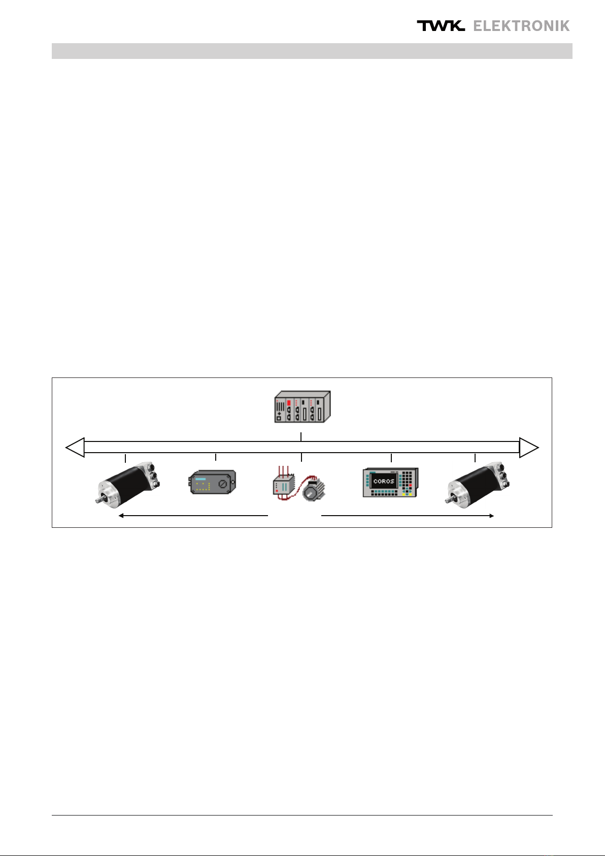
2 General ................................................................................................................................. 6
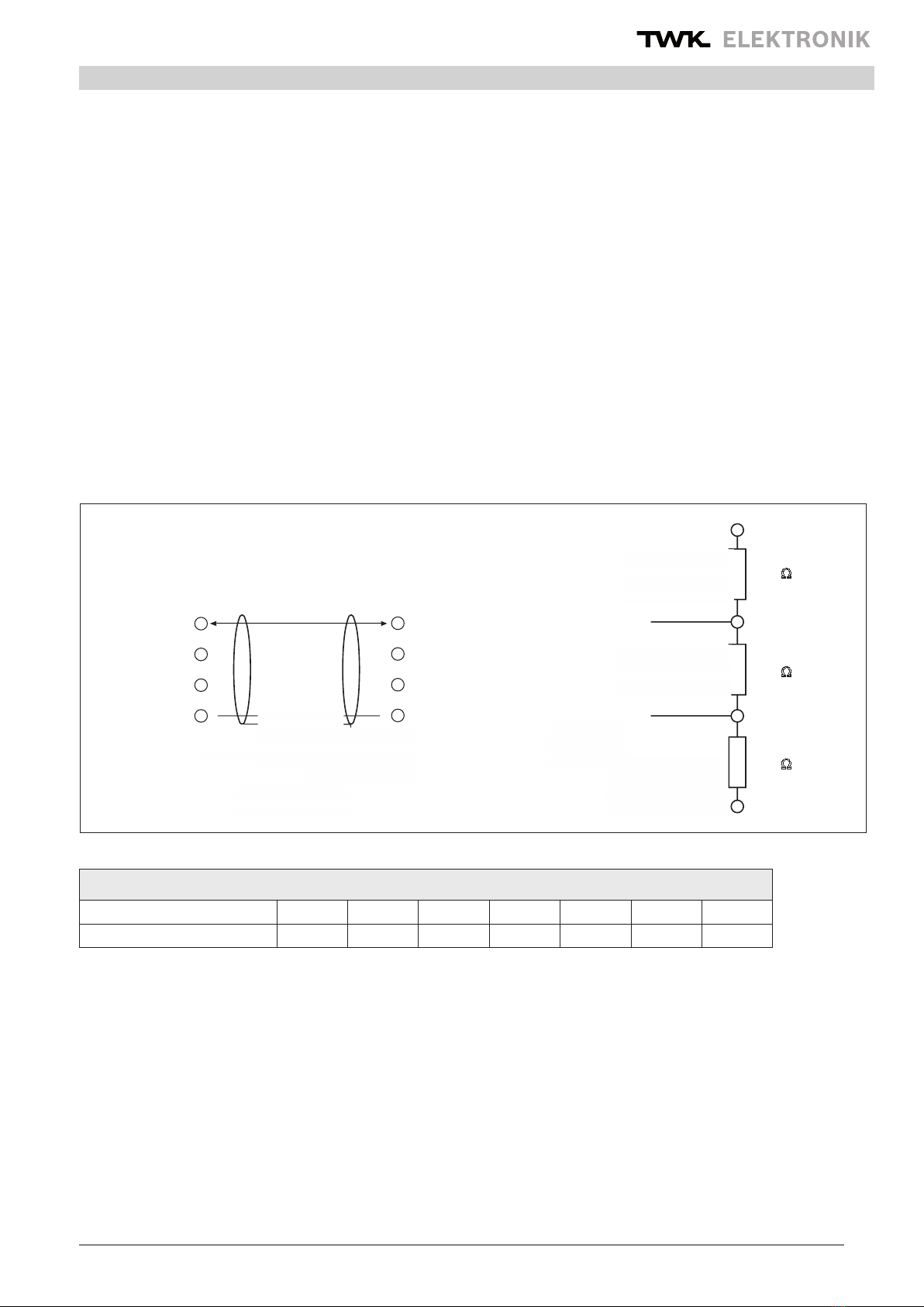
3. Installation instructions for PROFIBUS-DP - RS 485 ...................................................... 7
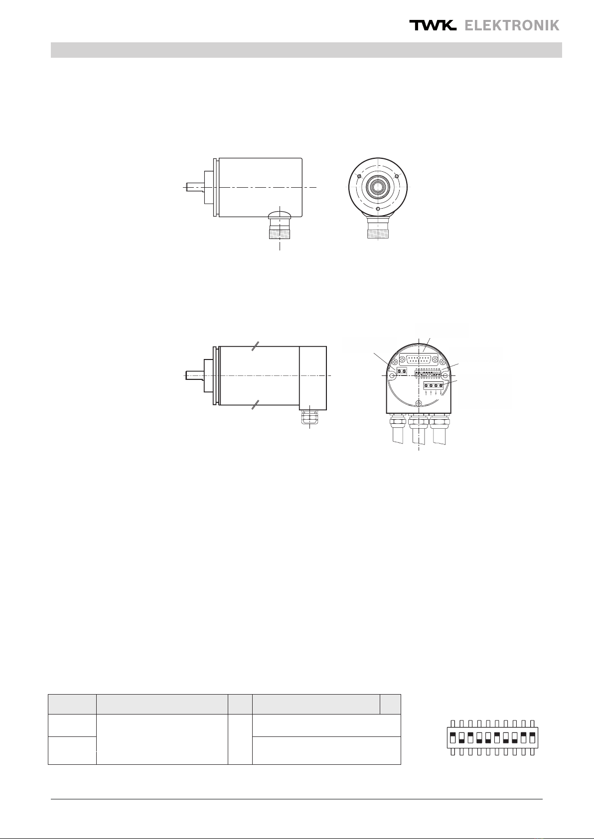
3.1 Connection of encoder with RS plug ...........................................................................................8
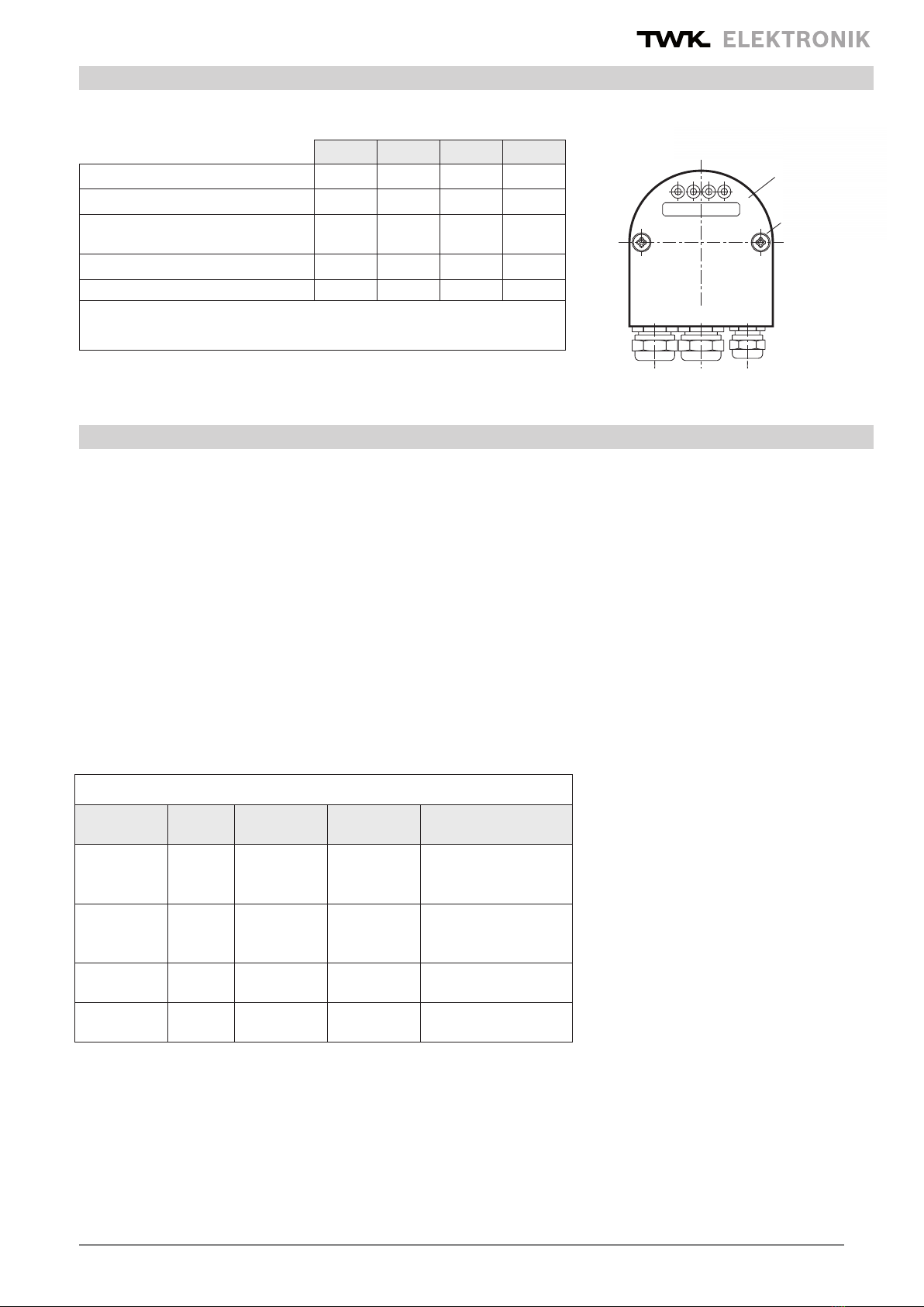
3.2 Connection of encoder with connecting cap ................................................................................8
4. Conguration function (DDLM_Chk_Cfg) ........................................................................ 9
5. Data exchange function (DDLM_Data_Exchange) ........................................................ 10
5.1 Actual position value ..................................................................................................................10
5.2 Set preset value.........................................................................................................................10
5.3 Example: Setting the preset value in 32 bit data format ............................................................ 11
6. Programming parameters for class 1/2 encoder (DDLM_Set_Prm) /4/........................ 12
6.1 Denition of the programming parameters ................................................................................12
6.1.1 Operating mode ...................................................................................................................12
6.1.2 Measuring units per revolution (Octet 10-13).......................................................................13
6.1.3 Total measuring range in units (Octet 14-17).......................................................................13
6.2 Examples for parametration (User_Prm_Data) .........................................................................14
7. Diagnosis messages (DDLM_Slave_Diag)..................................................................... 15
7.1 Standard diagnosis information (Octet 1-6): ..............................................................................15
7.2 Device-related diagnosis ...........................................................................................................15
7.2.1 Extended header byte (Octet 7): .........................................................................................15
7.2.2 Alarm messages (Octet 8):...................................................................................................16
7.2.3 Operating mode (Octet 9) ....................................................................................................16
7.2.4 Encoder type (Octet 10).......................................................................................................16
7.2.5 Single turn resolution (Octet 11-14) .....................................................................................16
7.2.6 Measuring range (Octet 15, 16) ...........................................................................................16
7.2.7 Additional alarm messages (Octet 17) ................................................................................16
7.2.8 Supported alarm messages (Octet 18,19) ...........................................................................17
7.2.9 Warning messages (Octet 20,21) ........................................................................................17
7.2.10 Supported warnings (Octet 22,23) .....................................................................................17
7.2.11 Prole version (Octet 24,25)...............................................................................................17
7.2.12 Software version (Octet 26,27) ..........................................................................................17
7.2.13 Operating time (Octet 28-31) .............................................................................................17
7.2.14 Offset value (Octet 32-35)..................................................................................................17
7.2.15 Manufacturer offset value (Octet 36-39) ............................................................................17

Date: 10.07.2012 Page 4 of 28 user manual no. CRD 10617 FE
Structure
7.2.16 Single turn resolution (Octet 40-43) ...................................................................................18
7.2.17 Total measuring steps (Octet 44-47) ..................................................................................18
7.2.18 Serial number (Octet 48-57) ..............................................................................................18
7.2.19 Reserved for future use (Octet 58,59) ...............................................................................18
7.2.20 Manufacturer-specic diagnosis (Octet 60-63) .................................................................18
7.2.21 Example of diagnosis message .........................................................................................19
8. Simatic Step7.................................................................................................................... 20
8.1 Integration of the TWK probus encoder ...................................................................................20
8.1.1 Installation of the GSD le ...................................................................................................20
8.1.2 Installation of the TWK encoder symbol...............................................................................20
8.1.3 Selection of the TWK encoder from the Step7 hardware catalogue ....................................20
8.1.4 Conguration of the encoder................................................................................................20
8.1.5 Allocation of probus address ..............................................................................................21
8.1.6 Setting the I/O addresses (S7 addresses) ...........................................................................22
8.1.7 Parameterisation of the encoder..........................................................................................22
8.1.8 Setting the diagnosis address..............................................................................................23
8.2 Setting the subscriber address in the case of the plug-version encoder ...................................23
8.3 Example programmes................................................................................................................24
8.3.1 The TWKDPCL1 project.......................................................................................................24
8.3.2 The TWKDPCL2 project.......................................................................................................25
8.3.3 Installation of the example programmes ..............................................................................25
8.3.4 Explanations regarding the example programmes ..............................................................27
9. Scope of delivery.............................................................................................................. 28
10. Literature......................................................................................................................... 28
Appendix A: Encoder terms ................................................................................................ 28

Date: 10.07.2012 Page 5 of 28 user manual no. CRD 10617 FE
Safety instructions
1. Safety instructions
1.1 Scope of validity
This user manual applies exclusively to the following rotary encoders with PROFIsafe interface:
- CRDxx-xxxxRxxxxC2Z01
- CRDxx-xxxxRxxxxC2L01
1.2 Documentation
The following documents must be noted:
- The owner's system-specic operating instructions
- This user manual
- Data sheet number CRD 10534
- The pin assignment enclosed with the device
- Installation instruction TZY 10206 enclosed with the device
1.3 Proper use
TWK-ELEKTRONIK GmbH's rotary encoders and linear transducers are used to record rotary and linear positions,
and make their measured values available as an electric output signal. As part of a system, they must be connected
to the downstream electronics and must only be used for this purpose.
1.4 Commissioning
• The relevant device must only be set up and operated using this document and the documentation specied
in point 1.2.
• Protect the device against mechanical damage during installation and operation.
• The device must only be commissioned and set up by a specialist electrician.
• Do not operate the device outside of the limit values which are specied in the data sheet.
• Check all electrical connections before commissioning the system.

Date: 10.07.2012 Page 6 of 28 user manual no. CRD 10617 FE
General
Differentiation of the services, and an exact knowledge of these, are especially important for understanding the
PROFIBUS-DP philosophy. A distinction is made between the following in the manual:
Check_Conguration: Conguration of the encoder
Integration of the encoder into the network with various data formats,
or as a programmable or non-programmable slave, is possible.
(Example: F1: programmable (32 bit input/output data) multitour encoder
Data_Exchange: Position data of the encoder
Cyclical enquiry regarding the encoder position. The position value is
depicted as a 16 bit or 32 bit value depending on the conguration.
Setting the preset value
Set_Parameter: Programming parameters
Denition of the operating mode of the encoder and denition of the values
for single turn resolution and total measuring range in units.
Slave_Diagnosis: Diagnosis of the slave subscriber (encoder)
2 General
The PROFIBUS is a eld bus standard according to EN 50170. The technical and functional characteristics of the eld
bus system are dened in this standard. The protocol architecture is based on the OSI reference model, in accordance
with the international ISO 7498 standard. Layer 1 (Physical Layer) denes the transmission physics, layer 2 (Data Link
Layer) the bus access protocol, and layer 7 (Application Layer) the application functions. This document is based on
the Prol description for encoders which can be obtained from the PNO /1/. The Probus protocol chip SPC 3 from
Siemens is used as the interface module between the encoder electronics and the bus system.
For PROFIBUS-DP, data exchange between SPS/PC and the decentralised periphery (e.g. encoder) is carried out in
a predominantly cyclical manner. For parameterisation, diagnosis and alarm handling purposes, acyclical communi-
cation functions are also required for intelligent eld devices. In this case, reference must be made to the DIN 19245
Part 1 and 3 or to the EN 50170 standards.
In the case of PROFIBUS-DP, communication in the data back-up layer (layer 2) is carried out via the SRD (Send and
Request Data with Reply) and SDN (Send Data with no Acknowledge) functions.
Mono or multi-master systems may be implemented with PROFIBUS-DP. A maximum of 126 devices (master or
slaves) may be connected to one bus. The denition of the system conguration contains the number of stations,
the allocation of the station address to the I/O addresses, data consistency of the I/O data, format of the diagnosis
messages and the bus parameters which are used.
The parameters of the PROFIBUS subscribers are described in a GSD le (device data sheet). The specications
are executed in accordance with DIN 19245 Part 3 /4/.
DP slaves
DP master (class 1)
PROFIBUS-DP

Date: 10.07.2012 Page 7 of 28 user manual no. CRD 10617 FE
Installation instructions
3. Installation instructions for PROFIBUS-DP - RS 485
Basic characteristics of RS-485 transmission technology /2/:
Network topology: Linear bus, terminating resistors for bus termination
Stub lines are only permissible in the case of baudrates < 1.5 MBit/s
Lead: Sheathed, twisted pair cable
Number of stations: 32 stations in each segment without repeaters
Can be extended up to 126 with repeaters.
Plug-type connector: Variants implemented in the case of the CRD model series:
Connecting cap, Round plug RS 25, 12-pin
DESINA (LWL and Cu-version)
(pin assignment according to /1/)
Wiring and bus termination for PROFIBUS-DP /2/, (Note: 9-pin Sub-D plug)
Cable type A specications: Characteristic impedance: 135...165 Ohm
Capacitance per unit length coating: < 30 pF/m
Loop resistance: 110 Ohm /km
Core diameter: 0.64 mm
Core cross-section: > 0.34 mm²
also see: Installation guideline for PROFIBUS -FMS/DP (PNO No. 2.111/2)
Implementation guide DIN 19245 Part 3 (PNO No. 2.001/2)
Station 1 Station 2
RxD/TxD-P (3)
DGND (5)
VP (6)
RxD/TxD-N (8) (8) RxD/TxD-N
(5) DGND
(3) RxD/TxD-P
(6) VP
Abschirmung
Schutz-
erde erde
Schutz-
Verkabelung Busabschluß
Datenleitung B
Datenleitung A
VP (6)
390
220
RxD/TxD-N (8)
390
DGND (5)
RxD/TxD-P (3)
Terminating
resistance of the bus
Data line A
Shield
Connection
Data line B
Transmission length depending on transmission speed for cable type A
Baud rate (kBit/s) 9,6 19,2 93,75 187,5 500 1.500 12.000
Transmission length in (m) 1200 1200 1200 1000 400 200 100

Date: 10.07.2012 Page 8 of 28 user manual no. CRD 10617 FE
Installation instructions
3.1 Connection of encoder with RS plug
The-pin assignment for the 12-pin RS plug (Note: Numeration of the-pins in clockwise direction (view facing contact
side of the bushing), encoder: Bushing) conforms to the prole denition for encoders /1/. The terminating resistors
must be implemented in the counterplug or in the subsequent electronics. For this connection type attention should
be paid to the length of the branch lines in the bus system and the total bus length.
When delivered, each encoder with RS plug has the default address 123. Via the DP master, it is possible to change
the address of a DP slave. The slave address which is to be newly assigned must lie within the range 1-126 (DDLM_
Set_Slave_Add).
3.2 Connection of encoder with connecting cap
The connecting cap for triple connection technology is a T-coupler, which is installed in the PROFIBUS.
It is equipped with three PG connections, which are subdivided as follows:
PG 7: Voltage supply for the encoder (24 VDC +/-)
PG 9: Bus in (Receive/transmit data A,B)
PG 9: Bus out (Receive/transmit data A’,B’)
The encoder is connected via the 15-pin SUB-D plug. In the event of an error, the encoder can be replaced without
time-consuming installation. The connecting cap is disconnected from the encoder by undoing 2 fastening screws
(Note: O-ring seal)
Setting the station/subscriber address is carried out via the DIP switches in the connecting cap.The address range lies
between 1 and 126 (Default address: 123). The address cannot be changed via the DDLM_Set_Slave_Add service.
(Note: GSD le in accordance with encoder version).
Setting the terminating resistors is carried out via the 10-fold DIP switch (9,10) in the connecting cap, which ay be
activated as lead termination as required.
Anschlußklemme 1
Anschlußklemme 2
(PROFIBUS)
BAA’ B’
15 polig/Buchse
Sub D Stecker
+ UB -
OFF
ON
DIP-Schalter
Sub-D - Connector
15 poles / sockets
DIP-Switch
Terminal 2
(PROFIBUS)
Terminal 1
DIP switch
OFF
ON
12345678910
DIP-Schalter
2 : 1
Switch 1 2 3 4 5 6 7 8 9 10
ON = 1 20 21... 27
n.c.
Termination resistors on
OFF = 0 Address 1 - 126 can be set Termination resistors off
(123: Default address)
DIP switch – address setting/terminating resistors

Date: 10.07.2012 Page 9 of 28 user manual no. CRD 10617 FE
Installation
Status LED (connecting cap)
4. Conguration function (DDLM_Chk_Cfg)
The absolute encoders with PROFIBUS-DP are classied as follows:
Encoder with Class 1 functionality
Class 1 devices are characterised by the fact that only the position value (16 bit or 32 bit) of the encoder is transmitted
via the bus. No parameterisation of encoder parameters is carried out. In this case, a distinction is made between
the D0 and D1 congurations. The D0 conguration contains the data format: 1 word input data, consistency and D1
contains 2 word input data, consistency.
Encoder with Class 2 functionality
Class 2 devices are characterised by the fact that they can be parameterised via the bus. In this case, a distinction
is made between the F0 and F1 congurations. The F0 conguration has the data format 1 word input data, 1 word
output data, consistency and F1 contains 2 word input data, 2 word output data, consistency .
Possible conguratons of the encoder:
PG9PG9 PG7
SRD
42
LED-Statusanzeigen
UB
Befestigungs-
schrauben M4
C Err
Status LED
Screw M4
Conguration
VS SRD C Err
Incorrect conguration x x x
Impermissible parameter x x x
Code error
(see diagnosis bytes 62 - 63) xx
Class 1 Gerätekonguration i.O. x x
Class 2 Gerätekonguration i.O. xxx
VS - power supply, Err - error, C - class, SRD - data trafc
Conguration function (DDLM_Chk_Cfg)
Selection Class Data Identier
byte
Assignment Octet-
No. and MSB/LSB
Class 2 32
Bit In/ Out 232 Bit In/
Output data F1 Octet 1/Bit 7: MSB
Octet 4/Bit 0: LSB
Class 2 16
Bit In/ Out 216 Bit In/
Output data F0 Octet 1/Bit 7: MSB
Octet 2/Bit 0: LSB
Class 1 32
Bit In 132 Bit Input
data D1 Octet 1/Bit 7: MSB
Octet 4/Bit 0: LSB
Class 1 16
Bit In 116 Bit Input
data D0 Octet 1/Bit 7: MSB
Octet 2/Bit 0: LSB

Date: 10.07.2012 Page 10 of 28 user manual no. CRD 10617 FE
Data exchange function
5. Data exchange function (DDLM_Data_Exchange)
Input data are data which are transmitted from the peripheral devices to the master or into the bus. The control of
the preset value (see below) is listed as an example of output data at this point.
5.1 Actual position value
The actual position value is output in 16 or 32 bit data format (input data), Please refer to the conguration of the
encoder in the previous chapter.
Input-Data
Octet 1 2
Bit (MSB) 15 - 8 7 - 0 (LSB)
Data 215 - 2827- 20
position value
Input-Data
Octet 1 2 3 4
Bit (MSB) 31 -
24 23 - 16 15 - 8 7 - 0 (LSB)
Data 231 - 224 223 -216 215 - 2827- 20
position value
5.2 Set preset value
The set preset value function should only be executed when the encoder shaft is stationary!
In order to compare machine position values and the absolute position of the encoder, setting the preset value
is unavoidable in certain cases. The preset value is the position value which is displayed in the reference point.
The possibility of setting the preset value is available in the case of the TWK encoder with class 2 functionality.
The user must note the fact that the preset value must lie within the total measuring range in units. In particular,
this must be taken into consideration when changing the total measuring range in units.
The preset value (binary code) is transmitted in data exchange mode by setting bit 31 (32 bit data format) or bit
15 (16 bit data format).
The following explanations refer to the 32 bit data format.
Setting the preset value in 32 data format
Output-Data
Octet 1 2 3 4
Bit 31 (MSB)30 - 24 23 - 16 15 - 8 7 - 0 (LSB)
Data 1/0 230 - 224 223 - 216 215 - 2827- 20
Preset Control reference value
Actual position value (DDLM_Data_Exchange) 32 bit data format
Actual position value (DDLM_Data_Exchange) 16 bit data format

Date: 10.07.2012 Page 11 of 28 user manual no. CRD 10617 FE
Data exchange function
Return to normal operation mode, 32 bit data format
After bit 31 = 0 has been reset, the encoder operates in normal operating mode. The offset value is stored in the diag-
nosis data and can be read in the event of a power failure and restarting (Also see Diagnosis messages in Chapter 7).
Following the receipt of this message, an offset value (from the current actual position value and preset value) is cal-
culated by the encoder. If the output position value is equal to the preset value, bit 31 can be reset by the master, as
the preset mode is terminated. The timing diagrams are specied in a separate TY sheet.
5.3 Example: Setting the preset value in 32 bit data format
Output-Data
Octet 1 2 3 4
Bit 31 30 - 0
00.0000.0000.0000.0000.0000.0000.1000
Data 1
Preset Control reference value: 8
Output-Data
Octet 1 2 3 4
Bit 31 30 - 0
00.0000.0000.0000.0000.0000.0000.1000
Data 0
Preset Control position value: 8

Date: 10.07.2012 Page 12 of 28 user manual no. CRD 10617 FE
Programming parameters
6. Programming parameters for class 1/2 encoder (DDLM_Set_Prm) /4/
The parameterisation data are comprised from bus-specic data and DP slave-specic data.
Bus-specic data: Octet 1-7 Octet 1 – Station status
Octet 2 - WD_Fact_1
Octet 3 - WD_Fact_2
Octet 4 - Min. station delay responder (min TSDR)
Octet 5 - Ident_Number 19
Octet 6 - Ident_Number 62H
Octet 7 - Group_Ident
DP slave-specic data: Octet 8-9 Class 1 encoder ( 2 byte User_Prm_Data)
Octet 8-29 Class 2 encoder (22 byte User_Prm_Data)
(See below for description)
Overview ot the encoder programming parameters
Octet number parameter data class remarks
8
9 operating status 1/2
10(MSB) - 13(LSB) Singleturn resolution 1 to 8192 steps/revolution
(1.000hex) 2
14(MSB) - 17(LSB) Total measuring steps 1 to 16.777.216 steps
(1.000.000hex) 2
18 - 29
6.1 Denition of the programming parameters
6.1.1 Operating mode
Logic table for Octet 9 (Operating parameters)
bit number parameter data class remarks
Bit 0 Code sequence
0: CW: Increasing clockwise
1,2
1: CCW: Increasing counter
clockwise
Bit 1 Class 2 functionality 0: not supported 1,2
1: supported
Bit 2 Commissioning diagnosis
control 0: not supported optional not supported
Bit 3 Scaling function status
0: disabled
2
enables the scaling
for resolution and total
measuring range
1: enabled

Date: 10.07.2012 Page 13 of 28 user manual no. CRD 10617 FE
Programming parameters
Denition of the operating parameters:
Code sequence: The code sequence denes the direction of rotation in which the position value corre-
sponds to increasing values (viewed in the direction of the shaft).
CW - clockwise
CCW - counter clockwise
Class 2: This operating parameter serves to distinguish between encoders with class 1 or class 2
functions.
Class 1 - Code sequence, release of the class 2 functions
Class 2 - Contains class 1 functions Scaling function control (see below)
Diagnosis: The diagnosis routine enables the extensive examination of all encoder components to ensure
routine: perfect functional capability. The routine is run through each time the device is switched on. If
faults are determined by the diagnosis routine, these are displayed with the alarm bit.
This function is not currently supported.
Scaling function: The scaling function control releases the parameterisation of the single turn resolution
and the total measuring range in units. This function is only effective when changing
the single turn resolution and total measuring range in units parameters. Following the
execution of scaling function control, the position value is recalculated and output.
6.1.2 Measuring units per revolution (Octet 10-13)
6.1.3 Total measuring range in units (Octet 14-17)
Note: It must be noted that the calculation of the number of revolutions is carried out in 2npowers internally within
the encoder. Regardless of this requirement, the user may programme the desired total measuring range in units
and the desired single turn resolution in accordance with the application. During calculation, the encoder accesses
the next highest 2n power if required. In this case, the values are designated as the actual single turn resolution or
as the actual total measuring range in units, and are displayed as the output value.
Example: desired total measuring range in units : 20480
desired single turn resolution : 4096
desired number of
revolutions : 5
internal encoder calculation
actual total measuring range in units : 32768
actual single turn resolution : 4096
calculated number of
revolutions : 8
Operating parameter resolution
Octet 10 11 12 13
Bit (MSB) 31-24 23-16 15-8 7-0 (LSB)
Data 231-224 223-216 215-2827-20
Operating parameter total measuring steps
Octet 14 15 16 17
Bit (MSB) 31-24 23-16 15-8 7-0 (LSB)
Data 231-224 223-216 215-2827-20

Date: 10.07.2012 Page 14 of 28 user manual no. CRD 10617 FE
Programming parameters
6.2 Examples for parametration (User_Prm_Data)
Class 1 encoder ( 9 parameter bytes, inclusive 7 bytes bus specid data)*
Class 2 encoder ( 29 parameter data, inclusive 7 bytes bus specic data)*
Class 1 encoder
bus specic data operating
status remarks
octet 01 - 07 08 09
data 00 00 Bit 0=0 code sense: CW
Bit 1=0 class1
data 00 01 Bit 0=1 codesense: CCW
Bit 1=0 class1
Class 2 encoder
bus specic
data operating status steps/
turn total steps
octet 01 - 07 08 09 10 - 13 14 - 17 18 - 29
data 00 0A
Bit 0=0 code sense: CW
1.000 1.000.000
Bit 1=1 class 2
Bit 2=0 no diagnosis
Bit 3=1 scaling on
data 00 0B
Bit 0=1 code sense: CCW
100 10.000
Bit 1=1 class 2
Bit 2=0 no diagnosis
Bit 3=1 scaling on
(Note: The above mentioned note must be taken into consideration in the event of irreversible operation. In the example
which is described, the position 0 is only achieved after 32767 steps and not, as desired, after 20479 steps.)
* example contains only DP-slave specic parameter data (see DIN 19245-3)

Date: 10.07.2012 Page 15 of 28 user manual no. CRD 10617 FE
Diagnosis messages
7. Diagnosis messages (DDLM_Slave_Diag)
Overview of diagnosis information
Explanations regarding the diagnosis information:
7.1 Standard diagnosis information (Octet 1-6):
For detailed description, see DIN 19245-3 /4/
(Note: Octet 5,6: Manufacturer identication: 1962H)
This manufacturer identication number is stored in the PNO, and identies the subscriber as a TWK encoder.
7.2 Device-related diagnosis
In the range from Octet 7 up to max. 244 (according to standard /4/), the DP slave may store its specic diagnosis.
7.2.1 Extended header byte (Octet 7):
In the header diagnosis (Octet 7), the length of the extended diagnosis bytes, including the header, is specied.
(Class 1 encoder: 0AH = 10 d
-> 6 (Standard diagnosis) + 1(Octet 7)+ 9 (Octet 8-16) = 16 diagnosis bytes,
Class 2 encoder: 39H = 57d
-> 6 (Standard diagnosis) + 1(Octet 7)+ 56 (Octet 8-63) = 63 diagnosis bytes)
Diagnosis octet
number diagnosis function class
1 - 6 standard diagnosis information 1, 2
device specic diagnosis
7extended headerbyte 1, 2
8 alarm messages 1, 2
9 operating parameters encoder 1, 2
10 encoder type 1, 2
11(MSB) - 14 (LSB) resolution 1, 2
15 - 16 measuring range 1, 2
End of diagnosis data for class 1 encoder!
17 additional alarm messages 2
18 - 19 supported alarm messages 2
20 - 21 warning messages 2
22 - 23 supported warnings 2
24 - 25 prol version 2
26 - 27 software version 2
28 - 31 operating time 2
32 - 35 offset 2
36 - 39 manufacturer offsetwert 2
40(MSB) - 43(LSB) resolution 2
44(MSB) - 47(LSB) total measuring steps 2
48 - 57 serial number 2
58 - 59 reserved 2
60 - 63 manufacturer specic diagnosis 2
Parameter extended headerbyte
Diagnosis octet 7
Bit 0-5 6 7
Data xxhex 0 0
Denition length inclusive
header
display of device
diagnosis

Date: 10.07.2012 Page 16 of 28 user manual no. CRD 10617 FE
Diagnosis messages
7.2.4 Encoder type (Octet 10)
The encoder type is set to multitour absolute. The code is stored in hexadecimal form (00-FFH)
7.2.2 Alarm messages (Octet 8):
Output of the current alarm status. TWK currently supports memory errors only.
7.2.3 Operating mode (Octet 9)
Current encoder status. This byte is described via the parameterisation of the master, and is read by the
diagnosis string.
7.2.5 Single turn resolution (Octet 11-14)
The maximum possible selection of measuring units per revolution, specied via the single turn resolution of the
encoder shaft. The value is stored in the binary code.
7.2.6 Measuring range (Octet 15, 16)
The maximum possible number of revolutions, specied via the single turn resolution of the multitour section.
Depiction in hexadecimal form, e.g. 4096 revolutions = 1000H.
7.2.7 Additional alarm messages (Octet 17)
Not currently assigned.
End of diagnosis data for class 1 encoder !
Parameter alarm messages
Diagnosis octet 8
Bit 0 1 2 3 45-7
Data 0=no /1=yes 0=no /1=yes 0=no /1=yes 0=no /1=yes 0=no /1=yes
Denition Position error Supply voltage
error Current to high Commissioning
diagnosis
Memory
error
currently not
assigned
Remarks not supported not supported not supported not supported supported
Parameter operating mode
Diagnosis octet 9
Bit 0 1 234-7
Data 0=CW /1=CCW 0=no /1=yes 0=no /1=yes 0=no /1=yes
Denition code sense class2
functionality
diagnosis
function
scaling
function
currently not
assigned
Remarks not supported
Parameter encoder type
Diagnosis octet 10
Bit 0-7
Data 01hex
Denition Multiturn absolut
Parameter resolution
Diagnosis octet 11 12 13 14
Bit (MSB) 31-24 23-16 15-8 7-0 (LSB)
Data 231-224 223-216 215-2827-20
Parameter measuring range
Diagnosis octet 15 16
Bit (MSB) 15-8 7-0 (LSB)
Data 215-2827-20

Date: 10.07.2012 Page 17 of 28 user manual no. CRD 10617 FE
Diagnosis messages
7.2.9 Warning messages (Octet 20,21)
This function is not currently supported.
7.2.10 Supported warnings (Octet 22,23)
This function is not currently supported.
7.2.11 Prole version (Octet 24,25)
Prole version: e.g. 01.00
7.2.8 Supported alarm messages (Octet 18,19)
The error entitled memory error is currently supported (10H).
7.2.12 Software version (Octet 26,27)
Software version: e.g. 01.00
Parameter supported alarm messages
Diagnosis octet 18 - 19
Bit 0 1 2 3 45-15
Data 0=no /1=yes 0=no /1=yes 0=no /1=yes 0=no /1=yes 0=no /1=yes
Denition Position error Supply voltage
error Current to high Commissioning
diagnosis
Memory
error
currently not
assigned
Remarks not supported not supported not supported not supported supported
Parameter prol version
Diagnosis octet 24 25
Bit 15-8 7-0
Data 215-2827-20
Denition revision number index
Parameter software version
Diagnosis octet 26 27
Bit 15-8 7-0
Data 215-2827-20
Denition revision number index
Parameter offset value
Diagnosis octet 32 33 34 35
Bit (MSB) 31-24 23-16 15-8 7-0 (LSB)
Data 231-224 223-216 215-2827-20
7.2.15 Manufacturer offset value (Octet 36-39)
The manufacturer offset is the shift in the zero point of the encoder with regard to its physical zero point.
The manufacturer offset value is not currently supported (Assignment: 00 00 00 00H).
7.2.14 Offset value (Octet 32-35)
The offset is the shift in the zero point on setting the reference point, with reference to the output
(according to the calculation).
7.2.13 Operating time (Octet 28-31)
This function is not currently supported. The operating time default is set as FFFF FFFFhex in accordance with the
encoder prole.

Date: 10.07.2012 Page 18 of 28 user manual no. CRD 10617 FE
Diagnosis messages
7.2.16 Single turn resolution (Octet 40-43)
In this case, the single turn resolution set in the parameter programme is reected.
7.2.20 Manufacturer-specic diagnosis (Octet 60-63)
Parameter single turn resolution
Diagnosis Octet 40 41 42 43
Bit (MSB) 31-24 23-16 15-8 7-0 (LSB)
Data 231-224 223-216 215-2827-20
Parameter total measuring steps
Diagnosis Octet 44 45 46 47
Bit (MSB) 31-24 23-16 15-8 7-0 (LSB)
Data 231-224 223-216 215-2827-20
Parameter serial number
Diagnosis Octet 48 49 50 51 52 53 54 55 56 57
Data 2A 2A 2A 2A 2A 2A 2A 2A 2A 2A
7.2.19 Reserved for future use (Octet 58,59)
Octet Nummer Bit Deniton Function Remarks
60 0 - 7 reserved
61 0 - 7 reservied
62 0 ErrEE EEPROM error reset encoder
1 ErrMSA MSA error reset encoder
2 ErrXRAM error external RAM reset encoder
3ErrExp error connectiong cap reset encoder
4 IniFlg initialising EEPROM
5 - 7 reserved
63 0 ErrCRCO CRC0 error re-program and restart
encoder
1 ErrCRC1 CRC1 error re-program and restart
encoder
2 ErrPar parameter value error re-program encoder
3ErrSkal scaling error
4 ErrMem ROM-Code error reset encoder
5 ErrInt internal controler error reset encoder
6 ErrPre referenz value error reference value must be
in the range of: 0 - total
measuring steps - 1
7 ErrStat unknown command
7.2.17 Total measuring steps (Octet 44-47)
In this case, the total measuring units per revolution set in the parameter programme is reected.
7.2.18 Serial number (Octet 48-57)
This parameter is not currently supported.

Date: 10.07.2012 Page 19 of 28 user manual no. CRD 10617 FE
Diagnosis messages
7.2.21 Example of diagnosis message
* If a faulty preset value is input, control bit 31 must be set to zero before inputting the correct preset value in order to eradicate
the error. The preset value can subsequently be reset after setting control bit 31 to 1. After resetting bit 31 to the value zero, the
position value may then be output.
Octet1234567891011 12 13 14 15 16
01-16 00 0C 00 02 19 62 39 00 0A 01 00 00 10 00 10 00
17-32 00 00 10 00 00 00 00 01 00 01 70 FF FF FF FF 00
33-48 00 0A D4 00 00 00 00 00 00 10 00 01 00 00 00 2A
48-63 2A 2A 2A 2A 2A 2A 2A 2A 2A 00 00 00 00 00 00
Explanation:
Octet: Parameter Data Remarks
1 - 6 Standard diagnosis
information
01 00 hex
02 0C hex Response monitoring activated,
bit 2 set to 1
03 00 hex
04 02 hex Parameterisation via master with
address 02
05 - 06 1962 hex Ident_Number CRD
7Extended header byte 39 hex 63 diagnosis bytes
8 Alarm messages 00 hex No alarms are present
9 Operating mode 0A hex CW, class 2, diagnosis: no, scaling
yes
10 Encoder type 01 hex Multitour, absolute
11 - 14 Single turn resolution 1000 hex 4096 S/U
15 - 16 Measuring range 1000 hex 16.777.216 Total measuring range
17 Additional
alarm messages 00 hex No alarms are present
18-19 Supported
alarm messages 0010 hex Memory error is supported
20-21 Warning messages 0000 hex wird nicht unterstützt
22-23 Supported
alarm messages 0000 hex wird nicht unterstützt
24-25 Prole version 01.00 Hardware version: 1.00
26-27 Software version 01.70 Software version: 1.70
28-31 Operating time FFFFFFFF hex
32-35 Offset value 00000AD4 hex Offsetwert
36-39 Manufacturer
offset value 00000000 hex Is not currently supported
40-43 Single turn resolution 00001000 hex 4096 S/U
44-47 Total measuring units
per revolution 01000000 hex 16.777.216 Schritte
48-57 Serial number 2A2A2A2A2A2A2A2A2A2A hex
58-59 Reserved
for future use 0000 hex
60-63 Manufacturer-
specic diagnosis 00000000 hex No errors are present

Date: 10.07.2012 Page 20 of 28 user manual no. CRD 10617 FE
Simatic Step7
8. Simatic Step7
This Chapter explains the procedure for integrating the TWK encoder into the probus of Siemens S7 control system,
and the set up and the utilisation of the example programmes for Step7. The basis of the documentation is Step 7
Version 5.1.
8.1 Integration of the TWK probus encoder
Prerequisites: You have congured your hardware in accordance with the structure of your control system, and
have installed a probus subnetwork.
8.1.1 Installation of the GSD le
- The GSD-le and the encoder symbols (bitmaps) are available under www.twk.de menu Documentation
- Close all projects in the hardware conguration.
- In the hardware conguration, select Install new GSD under Options.
- Select the GSD le which corresponds to your encoder:
Version with connecting cap: TWKZ1962.GSD
Version with plug connection: TWKL1962.GSD
- Update the Step7 hardware catalogue via Options, Update Catalog.
8.1.2 Installation of the TWK encoder symbol
Via the installation of the TWK encoder symbol, your encoder is not depicted as an unknown subscriber in the
hardware conguration, but assumes the appearance of your encoder. This is not, however, of signicance as
regards the function of the encoder.
In order to install the symbol (bitmap), copy the two les: CRD_Z_an.BMP and CRD_L_an.BMP into the C:\Siemens\
Step7\S7Data\NSBMP\ directory (if C: is your S7 drive). The symbols rst appear after restarting the Simatic Manager.
8.1.3 Selection of the TWK encoder from the Step7 hardware catalogue
- After opening the hardware catalogue, you will nd, under Probus-DP, Additional Field Devices, General,
the TWK Probus encoder "Encoder CRD plug" (encoder in plug version) or "Encoder CRD cap" (encoder
with connecting cap).
- Now open your project, mark the bus and integrate the encoder into the bus by double-clicking onto the
corresponding line in the hardware catalogue (Encoder CRD plug or Encoder CRD cap).
8.1.4 Conguration of the encoder
After the appropriate encoder type has been selected in the (hardware) Catalog, the following window appears for
the selection of encoder functionality and single turn resolution.
In this case, select class 1 or class 2 functionality and 16 or 32 bit single turn resolution in accordance with your
requirements. (See Chapter 4)
This manual suits for next models
1
Table of contents
Other TWK Elektronik Media Converter manuals