TYAN S8020 User manual

http://www.tyan.com
1
S8020
Version 1.0a
Copyright
Copyright © 2019 MiTAC International Corporation. All rights reserved. No part of
this manual may be reproduced or translated without prior written consent from
MiTAC International Corporation.
Trademark
All registered and unregistered trademarks and company names contained in this
manual are property of their respective owners including, but not limited to the
following.
TYAN®is a trademark of MiTAC International Corporation.
AMD®is a trademark of AMD®Corporation.
AMI, AMI BIOS are trademarks of AMI Technologies.
Microsoft®, Windows®are trademarks of Microsoft Corporation.
Winbond®is a trademark of Winbond Electronics Corporation.
Notice
Information contained in this document is furnished by MiTAC International
Corporation and has been reviewed for accuracy and reliability prior to printing.
MiTAC assumes no liability whatsoever, and disclaims any express or implied
warranty, relating to sale and/or use of TYAN®products including liability or
warranties relating to fitness for a particular purpose or merchantability. MiTAC
retains the right to make changes to product descriptions and/or specifications at
any time, without notice. In no event will MiTAC be held liable for any direct or
indirect, incidental or consequential damage, loss of use, loss of data or other
malady resulting from errors or inaccuracies of information contained in this
document.

http://www.tyan.com
2
Contents
S8020............................................................................................................1
Before you begin…....................................................................................4
Chapter 1: Instruction ................................................................................5
1.1 Congratulations .................................................................................5
1.2 Hardware Specifications....................................................................5
1.3 Software Specifications.....................................................................7
Chapter 2: Board Installation.....................................................................8
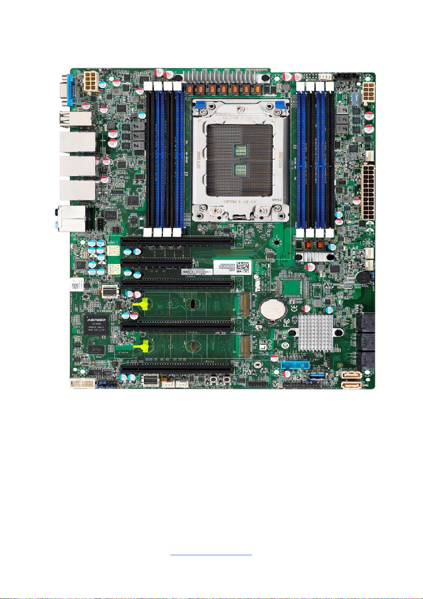
2.1 Board Image......................................................................................9
2.2 Block Diagram.................................................................................10
2.3 Motherboard Mechanical Drawing...................................................11
2.4Board Parts, Jumpers and Connectors ...........................................12
2.5 LED Definitions................................................................................20
2.6Installing the Processor and Heatsink.............................................23
2.7Thermal Interface Material...............................................................28
2.8Tips on Installing Motherboard in Chassis ......................................29
2.9Installing the Memory ......................................................................31
2.10 Attaching Drive Cables..................................................................35
2.11 Installing Add-In Cards..................................................................36
2.12 Connecting External Devices ........................................................37
2.13 Installing the Power Supply...........................................................39
2.14 Finishing Up...................................................................................39
Chapter 3: BIOS Setup .............................................................................40
3.1 About the BIOS................................................................................40
3.2 Main Menu.......................................................................................42
3.3 Advanced Menu...............................................................................44
3.4 Chipset Menu ..................................................................................85
3.5 Server Management........................................................................89
3.6Security............................................................................................94
3.7Boot .................................................................................................96
3.8Save & Exit......................................................................................99
Chapter 4: Diagnostics...........................................................................101
4.1 Flash Utility....................................................................................101
4.2 AMI BIOS Post Code (Aptio).........................................................102
4.3 AMD BIOS Post Code...................................................................109
Chapter 5: Configuring a RAID Set .......................................................141
Chapter 6 Windows®: Install AMD-RAID UEFI Drivers during Windows®
OS Installation.........................................................................................151
Appendix I: Fan and Temp Sensors .....................................................157

http://www.tyan.com
4
Before you begin…
Check the box contents!
The retail motherboard package should contain the following:
S8020 Motherboard x 1
SATA Single Cable x 2
Rear IO shielding x1
1 x S8020 Quick Installation Guide
IMPORTANT NOTE:
Sales samples may not come with any of the accessories listed above.
If you have ordered a sales sample and you are missing any of the above items,
please contact your sales representative to help order accessories.

http://www.tyan.com
5
Chapter 1: Instruction
1.1 Congratulations
You have purchased the powerful TYAN® S8020 motherboard, based on the AMD®
X399 chipset. The S8020 is designed to support AMD®Ryzen®Threadripper series
Processor, and Up to 256GB UDIMM ECC/Non-ECC DDR4 2933 MHz memory.
Leveraging advanced technology from AMD®, the S8020 is capable of offering
scalable 32 and 64-bit computing, high-bandwidth memory design, and lightning-
fast PCI-E bus implementation.
The S8020 not only empowers you in today’s demanding IT environment but also
offers a smooth path for future application upgradeability. All of these rich feature
sets provide the S8020 with the power and flexibility to meet demanding
requirements for today’s IT environments.
Remember to visit the TYAN® website at http://www.tyan.com. There you can find
all the information on all TYAN®products as well as all the supporting documentation,
FAQs, Drivers and BIOS upgrades.
1.2 Hardware Specifications
S8020AGM2NR-EX Specifications
Processor
Q'ty / Socket Type
(1) AMD Socket TR4
Supported CPU Series
(1) AMD Ryzen Threadripper Processor
Average CPU Power (ACP)
Wattage
Max up to 250W
Chipset
Chipset
AMD X399
Memory
Supported DIMM Qty
(8) DIMM slots
DIMM Type / Speed
UDIMM ECC/Non-ECC DDR4 2933
Capacity
Up to 256GB
Memory channel
4 Channels per CPU
Memory voltage
1.2V
Expansion
Slots
PCI-E
(1) PCI-E Gen2 x8 slot (w/ x4 link), (1) PCI-E Gen3
x16 slot (w/ x8 link), (3) PCI-E Gen3 x16 slots
LAN
Q'ty / Port
(2) GbE ports + (1) dedicated for IPMI
Controller
Intel I210
PHY
Realtek RTL8211E
Storage
SATA
Connector
(6) SATA, (2) SATA-DOM
Controller
AMD X399

http://www.tyan.com
6
Speed
6.0 Gb/s
RAID
RAID 0/1/10
NVMe
Connector (M.2)
(2) 2280 (by PCI-E interface)
Graphic
Connector type
D-Sub 15-pin
Resolution
Up to 1920x1200
Chipset
Aspeed AST2500
Audio
Chipset
Realtek ALC892-CG
Feature
7.1 ch
Input
/Output
USB
(4) USB 2.0 ports (4 at rear),
(2) USB3.1 Gen2 ports (at rear),
(2) USB3.1 Gen1 ports (via Cable),
(4) USB3.1 Gen1 ports (at rear),
(1) USB3.1 Gen1 port (Type-A)
COM
(1) header
VGA
(1) D-Sub 15-pin VGA port (at rear)
RJ-45
(2) GbE ports, (1) Dedicated for IPMI
Audio
(1) 5 holes Audio Jack+SPDIF fiber connector
Front Panel
(1) 2x12-pin SSI front panel header
SATA
(6) SATA-III connectors + (2) SATA-DOM connectors
Power
SSI 24-pin + 8-pin + 8-pin power connectors
System
Monitoring
Chipset
Aspeed AST2500
Fan
Total (6) 4-pin headers
Temperature
Monitors temperature for CPU & memory & system
environment
Voltage
Monitors voltage for CPU, memory, chipset & power
supply
LED
Fan fail LED indicator, Over temperature warning
indicator, Fan & PSU fail LED indicator
Others
Watchdog timer support
Server
Management
AST2500 iKVM Feature
24-bit high quality video compression, Supports
storage over IP and remote platform-flash, USB 2.0
virtual hub
AST2500 IPMI Feature
IPMI 2.0 compliant baseboard management controller
(BMC), 10/100/1000 Mb/s MAC interface
BIOS
Brand / ROM size
AMI, 32MB
Feature
Hardware Monitor, Boot from USB device/PXE via
LAN/Storage, User Configurable FAN PWM Duty
Cycle, Console Redirection, ACPI 6.1, SMBIOS
3.1/PnP/Wake on LAN, ACPI sleeping states
S0,S3,S4,S5
Physical
Form Factor
ATX

http://www.tyan.com
7
Dimension
Board Dimension
12"x9.6" (305x243.8mm)
Operating
System
OS supported list
Please refer to our AVL support lists.
Regulation
FCC (SDoC)
Class B
CE (DoC)
Class B
RCM
Class B
VCCI
Class B
Operating
Environment
Operating Temp.
0°C ~ 60°C (32°F~ 140°F)
Non-operating Temp.
- 40°C ~ 70°C (-40°F ~ 158°F)
In/Non-operating Humidity
90%, non-condensing at 35°C
RoHS
RoHS 6/6 Compliant
Yes
Package
Contains
Motherboard
(1) S8020 Motherboard
Manual
(1) Quick Installation Guide
I/O Shield
(1) I/O Shield
Cable SATA
(2) SATA signal cables
1.3 Software Specifications
For the latest AST2500 User’s Guide and OS (operation system) support, please
visit the Tyan’s Web site at http://www.tyan.com for the latest information

http://www.tyan.com
8
Chapter 2: Board Installation
You are now ready to install your motherboard.
How to install our products right… the first time
The first thing you should do is read this user’s manual. It contains important
information that will make configuration and setup much easier. Here are some
precautions you should take when installing your motherboard:
(1) Ground yourself properly before removing your motherboard from the
antistatic bag. Unplug the power from your computer power supply and
then touch a safely grounded object to release static charge (i.e. power
supply case). For the safest conditions, MiTAC recommends wearing a
static safety wrist strap.
(2) Hold the motherboard by its edges and do not touch the bottom of the
board, or flex the board in any way.
(3) Avoid touching the motherboard components, IC chips, connectors,
memory modules, and leads.
(4) Place the motherboard on a grounded antistatic surface or on the antistatic
bag that the board was shipped in.
(5) Inspect the board for damage.
The following pages include details on how to install your motherboard into your
chassis, as well as installing the processor, memory, disk drives and cables.
Caution!
1. To avoid damaging the motherboard and associated
components, do not use torque force greater than
5~7kgf/cm (4.35~6.09 lb/in) on each mounting screw
for motherboard installation.
2. Do not apply power to the board if it has been
damaged.

http://www.tyan.com
9
2.1 Board Image
S8020AGM2NR-EX
This picture is representative of the latest board revision available at the time of
publishing. The board you receive may not look exactly like the above picture.

http://www.tyan.com
10
2.2 Block Diagram
S8020 Block Diagram

http://www.tyan.com
11
2.3 Motherboard Mechanical Drawing

http://www.tyan.com
12
2.4 Board Parts, Jumpers and Connectors
This diagram is representative of the latest board revision available at the time of
publishing. The board you receive may not look exactly like the above diagram. The
DIMM slot numbers shown above can be used as a reference when reviewing the
DIMM population guidelines shown later in the manual. For the latest board revision,
please visit our web site at http://www.tyan.com.

http://www.tyan.com
13
Motherboard Components
Connectors
1. VGA connector (VGA1)
16. SATA connector (single port)
(SATA1/SATADOM2)
2. 4 ports stack USB2.0 Connector (J26)
17. SATA connector (single port)
(SATA0/SATADOM1)
3. IPMI LAN+USB3.1Gen1Connector (LAN6)
18. SATA connector (Dual ports) (SATA 2/3)
4. LAN2+USB3.1Gen2 Connector (LAN5)
19. SATA connector (Dual ports) (SATA 6/7)
5. LAN1+USB3.1 Gen1 Connector (LAN4)
20. SATA connector (Dual ports) (SATA 4/5)
6. Audio Jack (J103)
21. M.2 Slot Port 2 (M2_2)
7. Audio Front Header (FP_AUDIO_1)
22. SYS_FAN_3 (J31)
8. COM Port Header (COM1)
23. SYS_FAN_2 (J23)
9. SYS_FAN_5 (J28)
24. ATX Power Connector (24p) (J22)
10. SYS_FAN_4 (J30)
25. SYS_FAN_1 (J24)
11. M.2 Slot Port 1 (M2_1)
26. SSI 8-pin CPU and Memory Power Connector
(PWRCONN1)
12. TYAN Module Header (DBG_HD1)
27. PSMI Connector (J50)
13. USB3.0 Header (J29)
28. CPU FAN (J27)
14. Front Panel Header (FPIO_1)
29. SSI 8-pin Memory and PCIe Power Connector
(PWRCONN2)
15. Vertical Type A USB Connector (J193)
Jumpers
a. COM port select Jumper (J17)
e. Front Panel Reset Select Jumper (J20)
b. BMC COM(RX) port select Jumper (J15)
f. BUZZER Jumper (J19)
c. BMC COM(TX) port select Jumper (J16)
g. Reset BTN (RST_BTN1)
d. Clear CMOS Jumper (J1)
h. Power BTN (PWR_BTN1)
PCIE Slots
A PCIE3.0 SLOT x16 (PCIE#5)
C. PCIE3.0 SLOT x16 (PCIE#3)
B. PCIE2.0 SLOT x8 (PCIE#4)
D. PCIE3.0 SLOT x16 (PCIE#2)
E. PCIE3.0 SLOT x16 (PCIE#1)
LEDs
iREAR ID LED (LED1)
ix M.2 Slot Port 1 LED (LED_M1)
ii Memory Error LED-CH D1 (LED35)
x On Board BMC IPMI ALERT(IPMI_LED2)
iii Memory Error LED-CH D0 (LED31)
xi Memory Error LED-CH A0 (LED34)
iv Memory Error LED-CH C1 (LED37)
xii Memory Error LED-CH A1 (LED36)
v Memory Error LED-CH C0 (LED32)
xiii Memory Error LED-CH B0 (LED33)
vi BMC Heartbeat LED (BMC_HBLED1)
xiv Memory Error LED-CH B1 (LED38)
vii BMC Debug LED (BMC_DBLED1)
xv PSMI Alert LED (LED5)
viii M.2 Slot Port 2 LED (LED_M2)

http://www.tyan.com
14
SYS_FAN_5 (J28)/SYS_FAN_4 (J30)/SYS_FAN_3 (J31)/SYS_FAN_2 (J23)/
SYS_FAN_1 (J24)/ CPU FAN (J27): 4-pin Fan Connector
Pin
1
2
3
4
Signal
GND
VCC12
FAN_TACH
PWM
Use this header to connect the cooling fan to your motherboard to
keep the system stable and reliable.
COM1: COM Port Header
Signal
Pin
Pin
Signal
DCD
1
2
DSR
RTX
3
4
RTS
TXD
5
6
CTS
DTR
7
8
RI
GND
9
10
KEY
FP_AUDIO_1: Front Audio Header
Signal
Pin
Pin
Signal
FP_MIC_L
1
2
AGND
FP_MIC_R
3
4
AUDIO_Detect
AUO_HPOUT_R
5
6
AUO_SENSE_MIC
FIO_SENSE
7
8
NC
AUO_HPOUT_L
9
10
AUO_SENSE_HP
J193: Vertical (Type_A) USB3.0 Connector
Pin
Signal
1
+5V
2
USB2.0_DATA_N
3
USB2.0_DATA_P
4
GND
5
USB3.0_RX_N
6
USB3.0_RX_P
7
GND
8
USB3.0_TX_N
9
USB3.0_TX_P

http://www.tyan.com
15
SATA_1/SATADOM2/SATA_0/SATADOM1Connector:
Name
TYPE
1
GND
2
SATA TX DP
3
SATA TX DN
4
GND
5
SATA RX DN
6
SATA RX DP
7
GND
P1
VCC(P5V)
P2
GND
Connects to the Serial ATA ready drives via the Serial ATA cable.
SATA_2/3/ SATA_6/7/ SATA_4/5: 14-pin SATA 3.0 Connector
Name
TYPE
1
GND1
2
RX1+
3
RX1-
4
GND2
5
TX1-
6
TX1+
7
GND3
8
GND4
9
RX2+
10
RX2-
11
GND5
12
TX2-
13
TX2+
14
GND8
J29: USB3.0 Header
Signal
Pin
Pin
Signal
VCCUSB3_FRONT
1
2
USB30RX_4N_R
USB30RX_4P_R
3
4
GND
USB30TX_4N_R
5
6
USB30TX_4P_R
GND
7
8
USB_PCH DN2_R
USB_PCH DP2_R
9
10
USB_PCH_OC24_N_ID
USB_PCH_DP4_R
11
12
USB_PCH_DN4_R
GND
13
14
USB30TX_3P_R
USB30TX_3N_R
15
16
GND
USB30RX_3P_R
17
18
USB30RX_3N_R
VCCUSB3_FRONT
19
20
Key

http://www.tyan.com
16
DBG_HD1: TYAN Module Header
Signal
Pin
Pin
Signal
P3V3
1
2
FRAME_N
LAD0
3
4
KEY
LAD1
5
6
PLT_RST_N
LAD2
7
8
GND
LAD3
9
10
CLK_24M
DBG_SERIRQ
11
12
GND
DBG_PRES_N
13
14
3V3_VSB
GPIO1
15
16
GPIO2
FPIO1: Front Panel Header
Signal
Pin
Pin
Signal
LED PWR
1
2
VCC
NA
3
4
ID LED PWR
LED GND
5
6
ID LED GND
HDD LED PWR
7
8
HW FAULT
HDD ACT LED
9
10
SYS FAULT
PWR BUTTON
11
12
LAN0 LED P
GND
13
14
LAN0 LED N
RST BUTTON
15
16
SMBUS DAT
GND
17
18
SMBUS CLK
ID LED BUTTON
19
20
INTRUSION
SYS AIR INLET
21
22
LAN1 LED P
NMI BUTTON
23
24
LAN1 LED N
J50: PSMI Connector
Pin
1
2
3
4
5
Signal
SMB_CLK
SMB_DAT
SMB_ALERT#
GND
V3P3

http://www.tyan.com
17
M.2 Slot port 1 (M2_1)/ M.2 Slot port 2 (M2_2)
Pin
1
2
3
4
5
6
7
Signal
GND
3.3V1
GND
3.3V2
PE_RX
_3_N
N/C1
PE_RX
_3_P
Pin
8
9
10
11
12
13
14
Signal
N/C2
GND
DAS/DSS#
(I/O)/LED1#
(1)(0/3.3V)
PE_TX
_3_N
3.3V3
PE_TX
_3_P
3.3V4
Pin
15
16
17
18
19
20
21
Signal
GND
3.3V5
PE_RX
_2_N
3.3V6
PE_RX
_2_P
N/C3
GND
Pin
22
23
24
25
26
27
28
Signal
N/C4
PE_TX
_2_N
N/C5
PE_TX
_2_P
N/C6
GND
N/C7
Pin
29
30
31
32
33
34
35
Signal
PE_RX
_1_N
N/C8
PE_RX
_1_P
N/C9
GND
N/C10
PE_TX
_1_N
Pin
36
37
38
39
40
41
42
Signal
N/C11
PE_TX
_1_P
DEVSLP
(0/3.3V)
GND
N/C12
PE_RX
_0_N
N/C13
Pin
43
44
45
46
47
48
49
Signal
PE_RX
_0_P
N/C14
GND
N/C15
PE_TX
_0_N
N/C16
PE_TX
_0_P
Pin
50
51
52
53
54
55
56
Signal
PERST#
(o)(0/3.3V)
GND
CLK
REQ#(I/O)
(0/3.3V)
REF_
CLK_N
PEWAKE#
(I/O)(0/3.3V)
REF_
CLK_P
N/C17
Pin
57
58
59
60
61
62
63
Signal
GND
N/C18
Pin
64
65
66
67
68
69
70
Signal
N/C
SUSCLK
PEDET
3.3V7
Pin
71
72
73
74
75
76
77
Signal
GND
3.3V8
GND
3.3V9
GND
NC35
NC36

http://www.tyan.com
18
J194: CMOS Clear Jumper
Normal
(Default)
Pin
1
2
3
Signal
Vbat
P0_Vddbt_Rtc_G
GND
1-2 Normal RTC Reset (DEFAULT)
2-3 Clear RTC Registers
You can reset the CMOS settings by using this jumper. This can be
useful if you have forgotten your system/setup password, or need to
clear the system BIOS setting.
1. Power off system and disconnect power connectors from the
motherboard.
2. Remove the jumper from Pin_1 and Pin_2 (Default setting).
3. Move the jumper cap to close Pin_2 and Pin_3 for several seconds to
Clear CMOS.
4. Put jumper cap back to Pin_1 and Pin_2 (Default setting).
5. Reconnect power connectors to the motherboard and power on
system.
Clear CMOS
J17: COM port Select Jumper
Signal
Pin
Pin
Signal
AMD_COM_EN
1
2
GND
BMC_COM_EN
3
1-2: AMD COM PORT0
2-3: BMC CONSOLE PORT (Default)
J15: BMC COM PORT (RX) Select Jumper
Signal
Pin
Pin
Signal
BMC_RXD1
1
2
U1107 RXD1
BMC_RXD5
3
1-2: BMC COM Port1(Default)
2-3: BMC COMSOLE Port5
J16: BMC COM PORT (TX) Select Jumper
Signal
Pin
Pin
Signal
BMC_TXD1
1
2
U1107 TXD1
BMC_TXD5
3
1-2: BMC COM Port1(Default)
2-3: BMC COMSOLE Port5

http://www.tyan.com
19
J20: Front Panel Reset Select Jumper
Signal
Pin
Pin
Signal
COLD RST
1
2
FRONT RST
EXTRST
3
1-2: SYSTEM RESET(Default)
2-3: BMC RESET
J19: BUZZER Disable Jumper
Pin
1
2
3
4
Signal
VCC5
NA
BUZ_1
BUZ_2
Pin 3-4 Closed: Normal Mode (Default)
Pin 2-3 Closed: Disable PC Beep
Pin 1-4 Closed: Use the External Speaker
PWR_BTN1: POWER Button
Pin
1
2
3
4
Signal
PWR_BTN1
PWR_BTN1
GND
GND
RST_BTN1: Reset Button
Pin
1
2
3
4
Signal
RST
RST
GND
GND

http://www.tyan.com
20
2.5 LED Definitions
BMC_HBLED
BMC Heart
Beat LED
Pin
Signal
+
VDD_33_DUAL
-
N18131759
State
Description
OFF
OFF
The LED shuts off when the BMC
controller cannot be detected or
properly initiated.
Blinking
Green
The LED blinks per second to
indicate that the BMC controller is
working normally
LED34
memory channel
A0 error LED
Pin
Signal
+
VDD_33_SB
-
N18131759
State
Description
OFF
OFF
The LED shuts off when the DDR
status is fine
Bright
RED
The LED bright to show memory
error happened
LED36
memory channel
A1 error LED
Pin
Signal
+
VDD_33_SB
-
N18131759
State
Description
OFF
OFF
The LED shuts off when the DDR
status is fine
Bright
Red
The LED bright to show memory
error happened
LED33
memory channel
B0 error LED
Pin
Signal
+
VDD_33_SB
-
N18131759
State
Description
OFF
OFF
The LED shuts off when the DDR
status is fine
Bright
Red
The LED bright to show memory
error happened
LED38
memory channel
B1 error LED
Pin
Signal
+
VDD_33_SB
-
N18131759
State
Description
OFF
OFF
The LED shuts off when the DDR
status is fine
ON
Red
The LED bright to show memory
error happened
LED32
memory channel
C0 error LED
Pin
Signal
+
VDD_33_SB
-
N18131759
State
Description
OFF
OFF
The LED shuts off when the DDR
This manual suits for next models
1
Table of contents
Other TYAN Motherboard manuals

TYAN
TYAN THUNDER K8WE User manual

TYAN
TYAN THUNDER X User manual

TYAN
TYAN S3227 User manual

TYAN
TYAN TEMPEST I5000XT User manual

TYAN
TYAN S7100 User manual

TYAN
TYAN S7020 User manual

TYAN
TYAN THUNDER K8SE User manual

TYAN
TYAN Tsunami S1846S User manual

TYAN
TYAN TOMCAT I7230A User manual

TYAN
TYAN TSUNAMI AT User manual