Tyco Electronics AMP 1490530–1 User manual

Instruction Sheet
408–8653
E
2002 Tyco Electronics Corporation, Harrisburg, PA.
AllInternationalRightsReserved.
AMP and Tyco are trademarks.
*Trademark LOC B
1 of 4
TOOLINGASSISTANCECENTER1–800–722–1111
AMP FAX/PRODUCT INFO1–800–522–6752
For Regional Customer Service, visit our website at
www.tycoelectronics.com
This controlled document is subject to change.
For latest revision call the AMP FAX* number.
14 MAY 02 Rev O
Four–Pair UTP Cable Tester 1490530–1
Figure 1
Green Pair Lights
ShieldLight
ToneLight
ToneButton
Amber
PairLights
Detachable
Remote
BatteryLow
FaultLights
BatteryCap
1. INTRODUCTION
These instructions deal with the Four–Pair UTP
Tester 1490530–1 shown in Figure 1.
The Four–Pair UTP Cable Tester 1490530–1 is a
unique blend of a popular type of low–end tester
interface with an advanced microprocessor controller.
The most popular aspects of this type of tester are an
indication at both ends that the cable has been
tested, no buttons to push to perform a test and a
case that snaps together for storage. The
microprocessor brings the additional features of
automatic power management, split pair error
detection, direct indication of the type and location of
faults and tone generation.
2. DESCRIPTION
The main unit has four green pair lights, a green
shield light, four red fault lights, a red battery low light
and a green tone light. The remote unit has four
amber pair lights. When a connection from the main
unit to the remote is sensed, testing begins
automatically. On the main unit, the lights for each
pair will either be ON, OFF or FLASHING. An ON
light indicates a good pair, an OFF light indicates an
open pair and a FLASHING light indicates a bad pair.
If a pair is bad, one or more of the fault lights will be
flashing to indicate the type or types of faults. On the
remote unit, the pair lights are either ON or OFF. An
ON light indicates a good pair, and an OFF light
indicates an open or bad pair. Holding down the tone
button until all lights momentarily turn on starts the
debug mode. The pairs are stepped through one at a
time to display connection and fault information on a
pair–by–pair basis. A second press of the tone button
turns off debug or completion of two complete cycles.
When not in debug mode, pressing and releasing the
tone button in less than 1.5 seconds causes the
Four–Pair UTP Tester to generate a warble tone
signal on all pairs, flashing the tone light to indicate
tone is on. The tone will turn off automatically after
three hours, or with a second press of the tone
button.
3. SPECIFICATIONS
Specifications subject to change.
Electrical
Battery Life, typical Alkaline – Times are for the full capacity of the
battery used continuously in one of the following modes:
Standby: 2.5 years
Cable Testing: 20 hours
Tone Mode: 170 hours
Cable Types:
Shielded or Unshielded, Cat 5e, Cat 5, Cat 4, or Cat 3
Minimum Cable Length for Testing for Split Pairs:
1 meter (3 feet)Return Loss: 14db @ 600 ohms
Maximum Cable Length for Testing:
305 meters (1000 feet)
Coax Cable:
100 ohms maximum DC resistance, center conductor
plus shield
Environmental
Temperature – Operating: 0
_
to 50
_
C; Storage: –20
_
to 70
_
C
Humidity – 10% to 90%, non–condensing
Physical
Length: 14.5 cm [5.70 in]
Width: 7.2 cm [2.85 in]
Height: 3.0 cm [1.20 in]
Weight (with battery): 162 gm [(5.7 oz]
NOTE

408–8653
Four–Pair UTP Cable Tester 1490530–1
Rev O2 of 4
4. FEATURES
The Four–Pair UTP Cable Tester 1490530–1 contains
the following features:
S
Auto–on and auto–off when testing cables, by
plugging both ends into the tester
S
Cable test results displayed on main unit and
remote unit, in less than 2 seconds after
plugging in the cable
S
Snap–together case for easy storage and
convenient patch cable testing
S
Tone generator mode for use with tone tracers,
auto–off
S
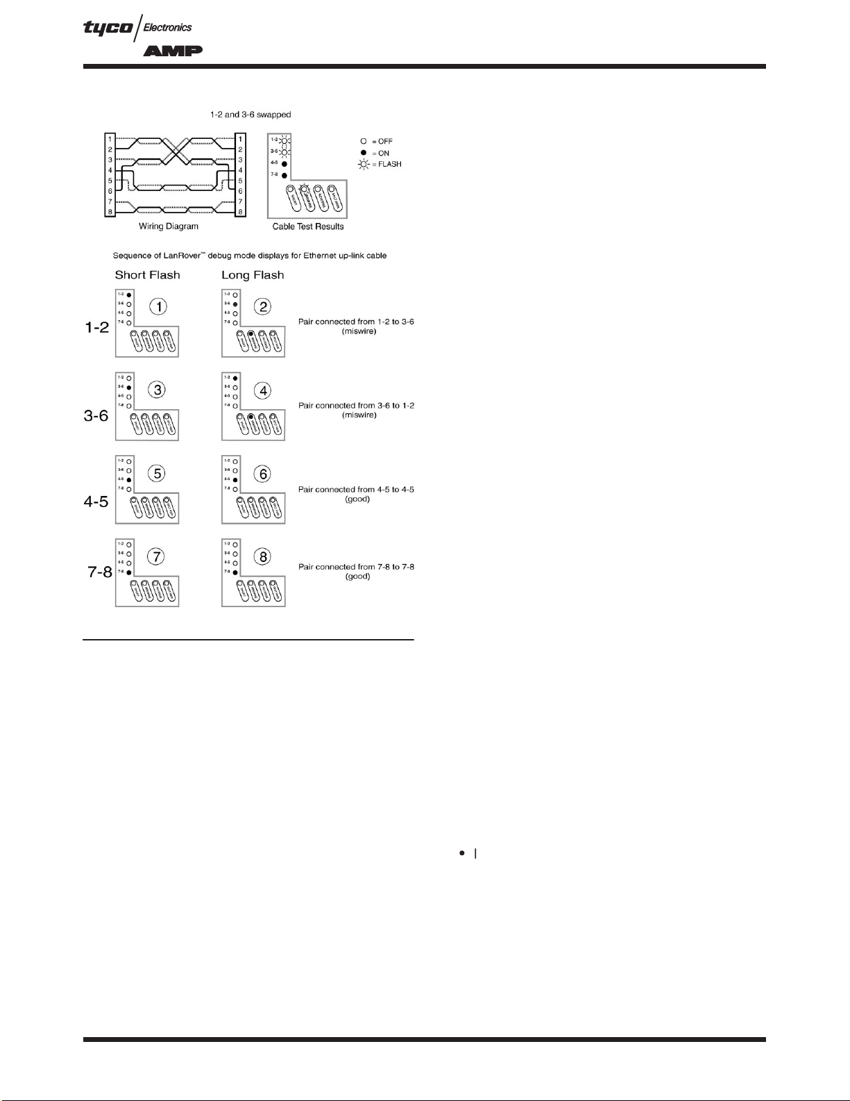
Debug mode with from/to and failures for each
pair
S
Battery low indicator
S
Tests for shorts, opens, miswires, reversals
and split pairs
5. OPERATION
To avoid personal injury, do not attach tester to
energized cables. This could cause personal
injury and may damage the Four–Pair UTP
Tester.
Improperly crimped or un–crimped plugs can
damage the jacks on the Four–Pair UTP Tester.
Inspect plugs for proper termination and crimping
before inserting into the tester. Contacts should
always be recessed into the plastic grooves of
theplug.
The Four–Pair UTP Tester powers off automatically
after five minutes of continuously testing a cable.
Disconnecting the cable restores normal function. Be
sure to install a battery if using for the first time–see
battery installation.
5.1. Testing a Patch Cable
1. Plug one end of patch cable into main unit.
2. Plug the other end of cable into remote unit.
3. The tester will power “on” immediately,
indicating a test in progress by quickly winking the
pair lights on both the main and remote; it will then
be followed by a combination of pair lights on – this
shows the test results. Refer to
Main Unit Results
and
Remote Unit Results
(Paragraphs 6.2 and
6.3).
4. Disconnect patch cable after test. The test
repeats automatically every 2.3 seconds if the
cable has only open and passing pairs and repeats
every four seconds if there are failures.
5.2. Testing an Installed Cable (Office Jack to Patch
Panel)
1. Remove the remote unit from main unit by
sliding remote towards top of the main unit.
2. Attach one end of supplied one–foot jumper
cable to remote and other end to wall jack.
3. Attach one end of the second supplied one–foot
jumper to main unit and the other end to the patch
panel jack.
4. The tester will power “on” immediately,
indicating a test in progress by quickly winking the
pair lights on both the main and remote; it will be
immediately followed by a combination of pair
lights on – this shows the test results. Refer to
Main Unit Results
and
Remote Unit Results
(Paragraphs 6.2 and 6.3)
5. Disconnect after the test. The test repeats
automatically every 2.3 seconds if the cable has
only open and passing pairs; and repeats every 4
seconds if there are failures.
–– ApplicationHints:
The jumper cables must be short compared to
the cable run for accurate split pair indication, no
more than ten% of the total run length.
5.3. Testing Coax (Requires Optional RJ45–to–Coax
Adapter)
1. Plug the RJ45 to 1“F” COAX adapters into the
remote and main units.
2. Attach cable to be tested to “F” connectors.
3. The tester will power “on” if it senses the cable.
If not, the cable is open. The coax adapter is
connected to the 1–2 pair and will be on steady if
good, or blink the 1–2 and short lights if shorted.
5.4. Placing a Tone on a Cable
1. Press and release the TONE button. The light
immediately above the button will start flashing.
2. Connect cable to be traced to main unit. For
best signal, do not connect remote. Due to the
shielding effect of twisted pairs, the strongest
signal is obtained by connecting only one wire in a
cable to the tone source.
3. To turn tone off, press the TONE button a
second time. The tone will turn off automatically
after three hours.
6. INTERPRETING RESULTS
6.1. Definition of Errors (Refer to Figure 2)
The four fault lights are discussed below in order of
severity. The severity has to do with the ability of the
DANGER
CAUTION
NOTE

408–8653
Four–Pair UTP Cable Tester 1490530–1
3of 4Rev O
type of error to mask lower severity errors. For
example, if there is a short in the cable, miswires,
reversals and split pairs cannot be detected for the
pairs involved in the short fault. Multiple faults on
multiple pairs can be better understood by using the
debug mode to examine the errors one pair at a time.
Short ––
The pair has a low resistance connection
from one wire of the pair to the other wire of the pair
or to any other wire in the cable or the shield. A single
flashing pair light and the short light indicate a short
within the pair. Multiple flashing pair lights and only
the short light indicate shorts between the pairs
involved.
Miswire ––
A wire or both wires of a pair are not
connected to the correct pins at the other end of the
cable. Debugs “from–to” format is very helpful in
visualizing specific miswires.
Reverse ––
A reverse is a special case of a miswire
in which the pair is wired to the correct pair of pins
or to another designated pair of pins, but the two
leads are reversed.
Split Pair ––
A split pair is an error in the twisting of
the wires together within the cable. The cables
generally are made up of eight wires twisted together
in 4 pairs. These 4 pairs are designated as pairs by
the wiring standards and are intended to carry a
signal and it’s return. 1 & 2, 3 & 6, 4 & 5 and 7 & 8
are the pairs designated. A cable can be wired with
correct continuity, but not with correct pairing. This
most often happens when the cable is terminated
consistently at both ends, but in the wrong order. A
dynamic or AC test is required to detect this type of
error. If the only error is a split pair error, the cable
has correct continuity. If cross talk is not a concern,
as in flat satin cable, the cable is good if the only error
is the split pair error.
6.2. Main Unit Results
The main unit indicates the beginning of a test by
flashing the pair lights in sequence top to bottom. The
cable is then tested and the results displayed as
follows:
Pair light off ––
Pair is open. Depending on the
wiring standard, this may be correct.
Pair light on ––
Pair is wired correctly.
Pair light is flashing ––
One or more errors were
detected for this pair, as indicated by flashing error
lights.
If there are
no
flashing lights, the results are
displayed for two seconds. If there
was
an error, the
results are displayed for twice as long.
Figure 2
6.3. Remote Unit Results
The remote unit indicates the beginning of a test by
flashing the pair lights quickly, the order or number of
lights flashed depends on the cable being tested.
The cable is then tested and the results displayed as
follows:
Pair light off ––
Pair is open or has a fault.
Depending on the wiring standard, this may be a
correct condition.
Pair light on ––
Pair is wired correctly.
If the there are no errors, the results are displayed for
two seconds. If there
was
an error, the results are
displayed for twice as long. If the lights for the pairs
expected are on, the cable is considered good.

408–8653
Four–Pair UTP Cable Tester 1490530–1
Rev O4 of 4
Figure 3
Ethernet Up–Link Cable Example
Debug Mode ––
(Refer to Figure 3) The debug
mode is provided to allow diagnosis of faults,
especially when there are multiple errors on multiple
pairs. To enter the debug mode, press and hold the
tone button until all lights on the main unit light (lamp
test). Once the lamp test is complete, debug displays
the results of the last cable test. This is from internal
memory, so the cable is not required to be connected
when running debug. The debug display begins with a
short flash on the 1–2 pair to indicate that what
follows is the result for the 1–2 pair test (or the
“from”). If the pair was not open, a second longer
flash on one or more pair lights designates what pair
1–2 is connected “to” at the remote end, or pairs
involved in a fault condition along with the fault lights.
The 3–6, 4–5 and 7–8 pair lights each in turn begin
with a short flash followed by the results for that pair.
The individual pair results continue to be displayed
until the tone button is pressed again or two complete
cycles of all pairs is completed. The remote unit does
not display anything when in debug mode.
7. BATTERY REPLACEMENT
When the battery low light is on while generating tone
or testing cables, the battery should be replaced as
soon as practical. The cable testing results will
become unreliable when the battery reaches about
4.5 volts.
To replace battery:
1. Remove rubber battery cap by peeling back a
corner until the cap pops off.
2. Pull battery out of cavity and remove battery
snap.
3. Connect a new Alkaline 9 volt battery to battery
snaps.
4. Slide battery into cavity and snap cap in place.
8. REPAIR/RETURN POLICY
Order replacement testers through your Tyco
Electronics representative, or call 1–800–526–5142,
or send a facsimile of your purchase order to
1–717–986–7605 or write to:
CUSTOMER SERVICE (38–35)
TYCO ELECTRONICS CORPORATION
P.O. BOX 3608
HARRISBURG, PA 17105–3608
For Four–Pair UTP Cable Tester repair service,
please contact a Tyco Electronics representative at
1–800–526–5136.
9. REVISION SUMMARY
Per EC 0990–0595–02:
S
Initial release of instruction sheet
Popular Test Equipment manuals by other brands

Buckleys
Buckleys BathyCorrometer Calibration Kit instruction manual

Extech Instruments
Extech Instruments MS420 user manual

Comelit
Comelit 41LTS000 Technical manual

Viavi
Viavi 7200 Series Operation manual

Bacharach
Bacharach Tru Pointe Operation & maintenance guide

Berkeley Varitronics Systems
Berkeley Varitronics Systems Cicada manual