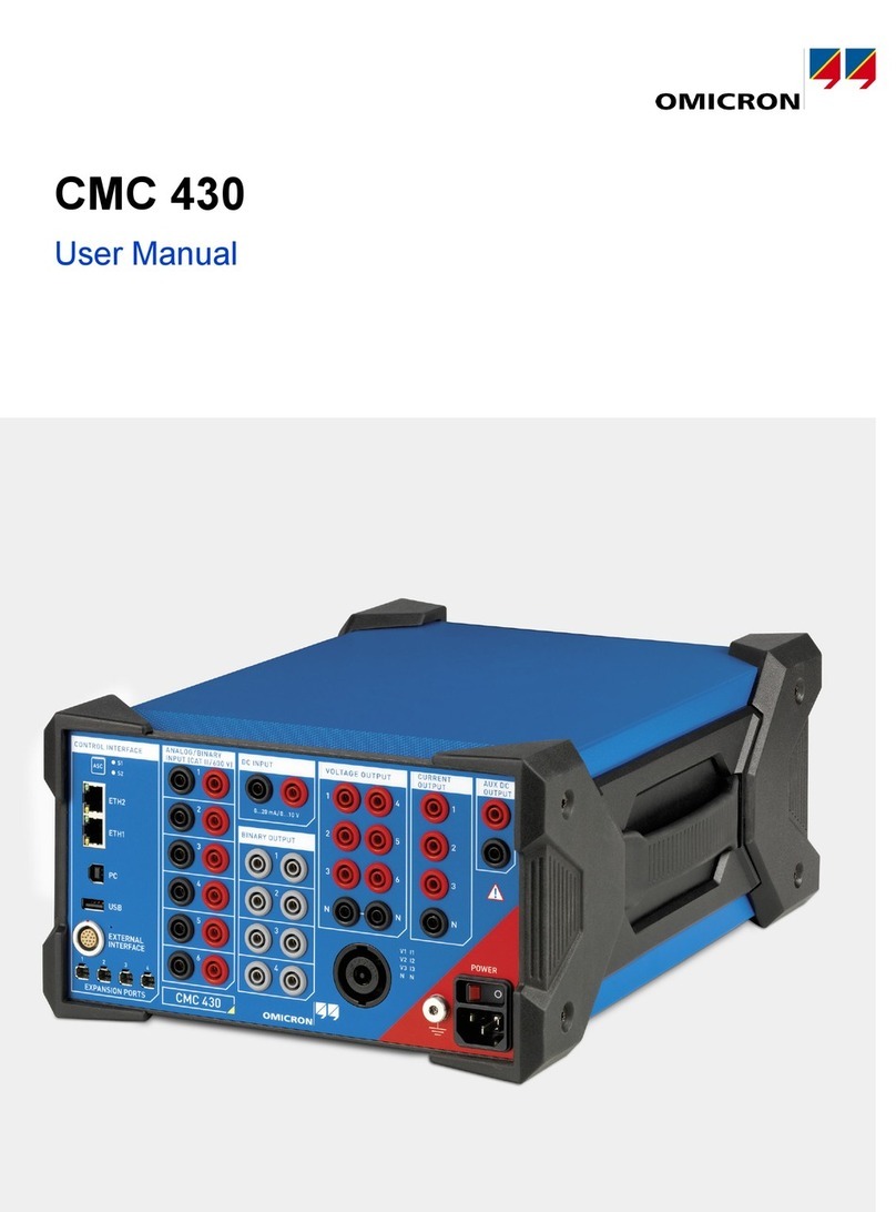
Omicron CMC 310 User manual

CMC 310
User Manual

CMC 310 User Manual
2OMICRON
Manual version: ENU 1012 05 01
© OMICRON electronics GmbH 2022. All rights reserved.
This manual is a publication of OMICRON electronics GmbH. All rights including translation reserved.
Reproduction of any kind, for example, photocopying, microfilming, optical character recognition and/or
storage in electronic data processing systems, requires the explicit consent of OMICRON. Reprinting,
wholly or in part, is not permitted.
The product information, specifications, and technical data embodied in this manual represent the
technical status at the time of writing and are subject to change without prior notice.
We have done our best to ensure that the information given in this manual is useful, accurate and entirely
reliable. However, OMICRON does not assume responsibility for any inaccuracies which may be
present. The user is responsible for every application that makes use of an OMICRON product.
OMICRON translates this manual from the source language English into a number of other languages.
Any translation of this manual is done for local requirements, and in the event of a dispute between the
English and a non-English version, the English version of this manual shall govern.

OMICRON 3
Table of contents
1 Preface 5
1.1 Web Interface . . . . . . . . . . . . . . . . . . . . . . . . . . . . . . . . . . . . . . . . . . . . . . . . . . . . . . . . . . . . . . . . . . 5
1.2 Open source license information . . . . . . . . . . . . . . . . . . . . . . . . . . . . . . . . . . . . . . . . . . . . . . . . . . . 5
2 Safety 6
2.1 Designated use . . . . . . . . . . . . . . . . . . . . . . . . . . . . . . . . . . . . . . . . . . . . . . . . . . . . . . . . . . . . . . . . 6
2.2 Safety symbols used . . . . . . . . . . . . . . . . . . . . . . . . . . . . . . . . . . . . . . . . . . . . . . . . . . . . . . . . . . . . 6
2.3 Safety instructions . . . . . . . . . . . . . . . . . . . . . . . . . . . . . . . . . . . . . . . . . . . . . . . . . . . . . . . . . . . . . . 6
2.4 Cleaning . . . . . . . . . . . . . . . . . . . . . . . . . . . . . . . . . . . . . . . . . . . . . . . . . . . . . . . . . . . . . . . . . . . . . . 8
2.5 Changing the power fuse . . . . . . . . . . . . . . . . . . . . . . . . . . . . . . . . . . . . . . . . . . . . . . . . . . . . . . . . . 8
3 Test set overview 9
3.1 Description . . . . . . . . . . . . . . . . . . . . . . . . . . . . . . . . . . . . . . . . . . . . . . . . . . . . . . . . . . . . . . . . . . . . 9
3.2 Front panel connections . . . . . . . . . . . . . . . . . . . . . . . . . . . . . . . . . . . . . . . . . . . . . . . . . . . . . . . . . . 9
3.2.1 VOLTAGE OUTPUT . . . . . . . . . . . . . . . . . . . . . . . . . . . . . . . . . . . . . . . . . . . . . . . . . . . . 10
3.2.2 CURRENT OUTPUT . . . . . . . . . . . . . . . . . . . . . . . . . . . . . . . . . . . . . . . . . . . . . . . . . . . . 11
3.2.3 BINARY INPUT . . . . . . . . . . . . . . . . . . . . . . . . . . . . . . . . . . . . . . . . . . . . . . . . . . . . . . . . 12
3.2.4 BINARY OUTPUT . . . . . . . . . . . . . . . . . . . . . . . . . . . . . . . . . . . . . . . . . . . . . . . . . . . . . . 12
3.2.5 AUX DC (DC power for test objects) . . . . . . . . . . . . . . . . . . . . . . . . . . . . . . . . . . . . . . . . 13
3.3 Back panel connections . . . . . . . . . . . . . . . . . . . . . . . . . . . . . . . . . . . . . . . . . . . . . . . . . . . . . . . . . 14
3.3.1 USB ports. . . . . . . . . . . . . . . . . . . . . . . . . . . . . . . . . . . . . . . . . . . . . . . . . . . . . . . . . . . . . 14
3.3.2 Ethernet port ETH1 . . . . . . . . . . . . . . . . . . . . . . . . . . . . . . . . . . . . . . . . . . . . . . . . . . . . . 15
3.3.3 ! button . . . . . . . . . . . . . . . . . . . . . . . . . . . . . . . . . . . . . . . . . . . . . . . . . . . . . . . . . . . . . . . 15
3.3.4 Associate button. . . . . . . . . . . . . . . . . . . . . . . . . . . . . . . . . . . . . . . . . . . . . . . . . . . . . . . . 15
3.3.5 Status LED A and B . . . . . . . . . . . . . . . . . . . . . . . . . . . . . . . . . . . . . . . . . . . . . . . . . . . . . 16
3.3.6 SELV interfaces . . . . . . . . . . . . . . . . . . . . . . . . . . . . . . . . . . . . . . . . . . . . . . . . . . . . . . . . 16
4 Technical data 18
4.1 Calibration and guaranteed values. . . . . . . . . . . . . . . . . . . . . . . . . . . . . . . . . . . . . . . . . . . . . . . . . 18
4.2 Main power supply . . . . . . . . . . . . . . . . . . . . . . . . . . . . . . . . . . . . . . . . . . . . . . . . . . . . . . . . . . . . . 19
4.2.1 Operational limits in conjunction with a weak power supply input voltage . . . . . . . . . . . . 19
4.2.2 Operational limits with current and voltage amplifier in parallel . . . . . . . . . . . . . . . . . . . . 20
4.3 System clock accuracy. . . . . . . . . . . . . . . . . . . . . . . . . . . . . . . . . . . . . . . . . . . . . . . . . . . . . . . . . . 20
4.4 Outputs. . . . . . . . . . . . . . . . . . . . . . . . . . . . . . . . . . . . . . . . . . . . . . . . . . . . . . . . . . . . . . . . . . . . . . 21
4.4.1 General generator outputs . . . . . . . . . . . . . . . . . . . . . . . . . . . . . . . . . . . . . . . . . . . . . . . . 21
4.4.2 Current outputs . . . . . . . . . . . . . . . . . . . . . . . . . . . . . . . . . . . . . . . . . . . . . . . . . . . . . . . . 22
4.4.3 Voltage outputs . . . . . . . . . . . . . . . . . . . . . . . . . . . . . . . . . . . . . . . . . . . . . . . . . . . . . . . . 25
4.4.4 Low-level binary outputs (ext. Interf.) . . . . . . . . . . . . . . . . . . . . . . . . . . . . . . . . . . . . . . . . 26
4.4.5 Binary output relays . . . . . . . . . . . . . . . . . . . . . . . . . . . . . . . . . . . . . . . . . . . . . . . . . . . . . 28
4.4.6 DC supply (AUX DC) . . . . . . . . . . . . . . . . . . . . . . . . . . . . . . . . . . . . . . . . . . . . . . . . . . . .29
4.5 Inputs . . . . . . . . . . . . . . . . . . . . . . . . . . . . . . . . . . . . . . . . . . . . . . . . . . . . . . . . . . . . . . . . . . . . . . . 30
4.5.1 Binary inputs . . . . . . . . . . . . . . . . . . . . . . . . . . . . . . . . . . . . . . . . . . . . . . . . . . . . . . . . . . 30
4.5.2 Counter inputs 100 kHz (low level) . . . . . . . . . . . . . . . . . . . . . . . . . . . . . . . . . . . . . . . . . 32
4.6 Technical data of the communication ports . . . . . . . . . . . . . . . . . . . . . . . . . . . . . . . . . . . . . . . . . . 34
4.6.1 NET-2 board. . . . . . . . . . . . . . . . . . . . . . . . . . . . . . . . . . . . . . . . . . . . . . . . . . . . . . . . . . . 34
4.6.2 NET-1C board (legacy board) . . . . . . . . . . . . . . . . . . . . . . . . . . . . . . . . . . . . . . . . . . . . . 35
4.7 Environmental conditions . . . . . . . . . . . . . . . . . . . . . . . . . . . . . . . . . . . . . . . . . . . . . . . . . . . . . . . . 35
4.8 Mechanical data . . . . . . . . . . . . . . . . . . . . . . . . . . . . . . . . . . . . . . . . . . . . . . . . . . . . . . . . . . . . . . . 36
4.9 Safety standards, electromagnetic compatibility (EMC) and certificates . . . . . . . . . . . . . . . . . . . . 36
4.10 Electrical insulation groups. . . . . . . . . . . . . . . . . . . . . . . . . . . . . . . . . . . . . . . . . . . . . . . . . . . . . . . 37
CMC 310 User Manual
4OMICRON
5 Increasing the output power 38
5.1 Current outputs. . . . . . . . . . . . . . . . . . . . . . . . . . . . . . . . . . . . . . . . . . . . . . . . . . . . . . . . . . . . . . . . 38
5.2 Voltage outputs . . . . . . . . . . . . . . . . . . . . . . . . . . . . . . . . . . . . . . . . . . . . . . . . . . . . . . . . . . . . . . . 39
6 Troubleshooting 40
6.1 Troubleshooting guide . . . . . . . . . . . . . . . . . . . . . . . . . . . . . . . . . . . . . . . . . . . . . . . . . . . . . . . . . . 40
6.2 Potential errors, possible causes, remedies. . . . . . . . . . . . . . . . . . . . . . . . . . . . . . . . . . . . . . . . . . 41
6.3 Overheating . . . . . . . . . . . . . . . . . . . . . . . . . . . . . . . . . . . . . . . . . . . . . . . . . . . . . . . . . . . . . . . . . . 41
Support 43

OMICRON 5
Preface
1 Preface
The purpose of this User Manual is to familiarize users with the CMC 310 test set hardware and its
specifications.
This manual is supplemented by the Safe use of CMC test sets manual, on-site safety regulations and
existing national safety standards for accident prevention and environmental protection.
The CMC 310 test set requires a suitable control software or control device for operation.
► Consult the corresponding Getting Started manual or user documentation regarding the use of the
control software or control device.
Note:
• The Safe use of CMC test sets manual and the software manuals are supplied on CD/DVD together
with this User Manual.
• From time to time the manual is updated to reflect the actual development status or changes of the
test set’s functional range. See page 2 for this manual’s version number.
1.1 Web Interface
The CMC 310 test set is additionally equipped with a Web Interface. The Web Interface enables you to
view device-specific parameters, and – depending on the device type – even provides you with
configuration features.
For more detailed information, see the according Web Interface help.
► Launch the Web Interface of that particular device, then click its help command. The Web Interface
is launched from the OMICRON Device Link tool.
1.2 Open source license information
Parts of the CMC 310 test set software are under OMICRON license, other parts are under open source
software licenses. Both the open source license texts and the necessary source code are provided in
the OMICRON Open Source Download Area at www.omicronenergy.com/opensource.
Open this address in your Internet browser, click the Download Software button, and navigate to the
CMC Embedded Image directory.
► Look for the file containing your version in the file name (for example, Open Source CMC embedded
Image 2.59.zip for version 2.59).
In addition to some open source code packages, the archive contains an overview of all license
information of the CMC test set.
WARNING
Death or severe injury caused by dangerous voltage possible
►Operate the CMC 310 only after you have read and fully understood the Safe use of
CMC test sets manual.

CMC 310 User Manual
6OMICRON
2 Safety
2.1 Designated use
The CMC 310 is a test set controlled by the CMControl P software for the testing of protection relays,
energy meters, SCADA systems and devices.
► Do not use CMC test sets in any other way than described in this document or in working
environments that exceed the specifications given in section 4 "Technical data". Improper use may
result in damage to persons or property.
2.2 Safety symbols used
In this document, the following symbols indicate safety instructions for avoiding hazards.
2.3 Safety instructions
► Before operating a CMC test set, carefully read the following safety instructions.
► Only operate (or even turn on) the CMC test set after you have read this manual including section
4 "Technical data" on page 18, and fully understood the instructions. We also recommend to read all
other relevant documentation for your test set and control software.
For your safety
Only trained personnel may operate CMC test sets. Any maloperation can result in damage to property
or persons.
You can remotely activate CMC test set outputs if the CMC is turned on and connected to a suitable
control software or control device (via network, wireless or USB).
► Observe all necessary safety measures given below.
All 4 mm safety sockets on the front panel can carry signals at dangerous levels and can conduct
dangerous voltages.
WARNING
Death or severe injury can occur if the appropriate safety instructions are not
observed.
NOTICE
Equipment damage or loss of data possible.

OMICRON 7
Safety
Rules for use
► Before operation, visually check for damages and make sure that the device and its accessories are
in a technically sound condition.
►Use CMC test sets only in accordance with the safety regulations for the specific job site and
application.
► Follow the instructions provided in the documentation.
► Testing with CMC test sets shall only be carried out by authorized and qualified personnel. Before
starting to work, clearly establish the responsibilities of all personnel involved.
► Personnel operating CMC test sets must be familiar with all necessary personal safety equipment.
► Testing with CMC test sets must comply with all on-site procedures and methods for personal safety.
► Personnel receiving training, instruction, direction, or education on CMC test sets should remain
under the constant supervision of an experienced operator while working with the equipment.
► Keep this document available on site where the CMC test sets are used.
Safe operation procedures
► Ensure proper grounding of the device and of the equipment under test.
► Use a power supply with protective earth.
► The power cable must be rated for the nominal voltage and current specified in section 4.2 "Main
power supply" on page 19. We recommend to use the cable supplied with the test sets.
► Do not block the access to safety-relevant test set components like the power switch or the power
cable.
►Operate CMC test sets only under the environmental conditions specified in section
4.7 "Environmental conditions" on page 35. Especially avoid a condensing environment.
► Do not operate CMC test sets when explosive gas or vapors are present.
► When setting up CMC test sets, make sure that the ventilation holes on the rear of the device remain
unobstructed.
► The fuse (→ section 2.5 "Changing the power fuse" on page 8) is the only serviceable part in CMC
test sets. Do not open CMC test sets or carry out any modifications, extensions, or adaptations.
►If CMC test sets seem to be functioning improperly, please contact OMICRON Support.
► Falling adapters or cables are a hazard. Test leads wired to tall test objects must be secured
mechanically.
► Do not connect any of the front panel outputs of VOLTAGE OUTPUT or CURRENT OUTPUT to
protective earth. The N sockets, however, may be connected to protective earth.
► Do not connect high inductive loads to CMC test sets.
► Observe the wiring instructions and safety precautions given in the Safe use of CMC test sets
manual.

CMC 310 User Manual
8OMICRON
2.4 Cleaning
Cleaning procedure:
1. Switch off the power switch.
2. Unplug the power cable from the power outlet.
3. Clean the CMC test set with a cloth dampened with isopropanol alcohol.
2.5 Changing the power fuse
Proceed as follows to replace the power fuse on your CMC test set:
1. Unplug the power cable of the CMC test set from the power outlet.
2. Locate the fuse on the back of the CMC test set.
3. Replace the fuse by an identical fuse type: Schurter 0001.2515 (T12.5 AH 250 V).

OMICRON 9
Test set overview
3 Test set overview
3.1 Description
The CMC 310 is a test set controlled by the CMControl P software. This User Manual describes the
hardware of the CMC 310. The configuration and control of the CMC 310 is carried out by the
CMControl P software. For more detailed information, read the user documentation.
3.2 Front panel connections
WARNING
Death or severe injury caused by dangerous voltage possible
All outputs and inputs of CMC test sets that are not explicitly restricted to SELV can carry
lethal voltage. The insulation between input and output groups on the front panel is only a
functional insulation and not sufficient to prevent dangerous voltages from being bridged
between ports. In case of an internal failure input ports can also be a source of
dangerous voltages.
► Before working on test objects, connections or terminals connected to the CMC test
set, make sure that the power supply of the CMC test set is switched off and that all
parts in the working area are de-energized.
► Observe the correct wiring procedure.
1VOLTAGE OUTPUT 3×300V
RMS output of the internal voltage amplifier
2AUX DC Output voltage in 3 ranges from 0 to 264 V;
used to supply power to test objects
3BINARY OUTPUT 4 potential-free relay contacts
4POWER switch
5BINARY INPUT 6 binary inputs in 3 galvanically separated groups
6CURRENT OUTPUT 3×32A
RMS output of the internal current amplifier
1 2 3
6 5 4

CMC 310 User Manual
10 OMICRON
3.2.1 VOLTAGE OUTPUT
The 3 voltage outputs have a common neutral (N) that can be connected to protective earth, if required.
→ Section 4.4.3 "Voltage outputs" on page 25.
The amplifier is galvanically separated from all other connectors of the CMC 310.
All voltage outputs are protected against open circuits, L-N short circuits, overload, and
overtemperature.
► Do not connect any of the outputs of VOLTAGE OUTPUT to protective earth.
NOTICE
Equipment damage possible
An external infeed could damage the CMC test set.
► Make sure that there is no infeed from an external source.

OMICRON 11
Test set overview
3.2.2 CURRENT OUTPUT
→ Section 4.4.2 "Current outputs" on page 22.
Each output is galvanically separated from all other connections of the
CMC 310. All current outputs are protected against open circuits, short
circuits, overload, and overtemperature.
WARNING
Death or severe injury caused by dangerous inductive loads possible
If charged with current, inductive loads may store a dangerous amount of energy. For
example, an energy of <350 mJ is considered safe according to the IEC 61010-1 safety
standard.
► Make sure that the possibly stored energy of the inductive device under test is within
safe limits.
► Do not use the CMC test set for the measurement on high inductances (power
transformer, current transformer) due to the discharging processes.
► If in doubt, contact OMICRON Support for more information.
WARNING
Death or severe injury caused by dangerous voltage levels on conductive parts
possible
Although the output voltages of the current generators are within touch-safe limits, the
insulation to other input and output groups is implemented as functional insulation only.
Therefore, the outputs can conduct dangerous voltages.
► Observe the wiring instructions and safety precautions given in section "Wiring" in the
Safe use of CMC test sets manual.
► Do not touch open conductive parts with live current signals (e.g. blank screw
terminals) while the CMC test set is switched on.
NOTICE
Equipment damage possible
An external infeed could damage or destroy the current output. The outputs are protected in switched-
off state by a short-circuit relay.
► Make sure that there is no infeed from an external source.

CMC 310 User Manual
12 OMICRON
3.2.3 BINARY INPUT
All 6 inputs of the CMC 310 can be individually configured by the control software to be binary inputs
(wet = potential-sensing or dry = potential-free). When the contacts are potential-sensing, the expected
nominal voltage can be set for each binary input.
The 6 inputs are divided into 3 groups of 2 inputs, each group galvanically separated from the others.
Moreover, the binary inputs 1 to 6 can be used as counter inputs for input frequencies up to 3 kHz.
3.2.4 BINARY OUTPUT
The 4 potential-free normally open relay contacts can switch AC or DC
currents of up to 8 A.
Technical data → Section 4.4.5 "Binary output relays" on page 28.

OMICRON 13
Test set overview
3.2.5 AUX DC (DC power for test objects)
The AUX DC output can be used to supply test objects with DC voltage. The output voltage
can be configured to 0 … 264 V in the control software or control device.
► Refer to the documentation of the control software for more information.
The AUX DC output is galvanically separated from all other connections of the CMC 310.
The output is protected against short-circuit, overload, and overtemperature.
An LED in the upper left corner indicates if the output is active.
WARNING
Death or severe injury caused by dangerous voltage levels due to control by
software possible
The AUX DC output can be programmed to output dangerous voltage. This may lead to
damage to property or persons. Since the output is only controlled by software, a wrong
AUX DC setting (e.g. set in software, software or hardware error) could lead to an
unexpected value (up to 264 V).
► Make sure that the voltage applied at the AUX DC output of the CMC test set interface
is safe before connecting any test leads to this output.
► Follow the wiring procedure described in section "Wiring" in the Safe use of CMC test
sets manual.
LED status Description
Red Output is active
OFF Output is inactive

CMC 310 User Manual
14 OMICRON
3.3 Back panel connections
Rear view of the CMC 310 with the NET-2 interface board:
3.3.1 USB ports
USB port type A is used to insert USB peripherals such as wireless USB adapters. Only
OMICRON-supplied wireless USB adapters are supported.
USB port type B is used to connect the CMC 310 to your computer.
► To improve electromagnetic compatibility, use the OMICRON-supplied cable.
For the technical data of the USB port see section 4.6 "Technical data of the communication ports" on
page 34.
1 Power supply, fuse T12.5 AH 8 Ethernet ports ETH1 and ETH21
1. The hardware for LL out 1–6 and ETH2 exists but is not used in the CMC 310.
2 Fans for power supply 9 ! button
3 External interface ext. Interf. 10 Interfaces LL out 1– 61
4 Status LEDs A and B 11 Grounding socket
Used to connect the CMC test set to protective earth
using a grounding cable if grounding via the power
outlet is insufficient (see section "Grounding" in the
Safe use of CMC test sets manual).
5Associate button
6USB ports type A and B
7 Fans for current and voltage outputs

OMICRON 15
Test set overview
3.3.2 Ethernet port ETH1
Depending on the interface board of your CMC test set, the PoE Ethernet (Power over Ethernet)
port ETH1 is of one of the following types:
• 10/100Base-TX (twisted pair) Ethernet port (at NET-1C board)
• 10/100/1000Base-TX (twisted pair) Ethernet port (at NET-2 board)
They support auto crossing (auto MDI/MDIX). This means you can use a standard cable or a
cross-over Ethernet patch cable.
→ Section 4.6 "Technical data of the communication ports" on page 34.
The yellow and green LEDs at the ETH port reflect the port’s operational status. Depending on your NET-
x interface board, their behavior slightly varies.
→ Section 4.6 "Technical data of the communication ports" on page 34.
3.3.3 ! button
The !button enables you to recover from unsuccessful software image downloads or other issues.
To start a new software image download, press the !button with a pointed tool or a paper clip while
powering up the CMC. In that case, the test set will not start as usual but wait for a new software
image download.
3.3.4 Associate button
The Associate button has the following functions:
•Association with controlling computer
An Ethernet communication port enables you to communicate with any CMC available on the
network. This may lead to dangerous situations where a user accidentally connects to a device
located on a desk of somebody else, emitting unsafe voltages and endangering the person working
there.
To prevent such a situation, a mechanism is integrated into the CMC test set that allows only
"authorized" clients to control the test set. If you use the Associate button, the test set is registered
for use with a specific host computer.
The association process can be initiated via the control software.
► For more details about this process, refer to the according help.
For the association, the CMC test set remembers the Ethernet hardware address (MAC) of the
connected port of the controlling device. Should the port change, a re-association is necessary.
•Reset IP configuration
If the Associate button is pressed while powering up the CMC test set, the IP configuration of the
network interfaces is reset to factory default, which is DHCP/AutoIP for both network interfaces. This
may be necessary to recover from settings with conflicting static IP addresses.
!
Associate

CMC 310 User Manual
16 OMICRON
3.3.5 Status LED A and B
The status LEDs A and B above the Associate button are of interest in case of troubleshooting.
A: yellow status LED
• ON indicates that the test set is ready to be controlled by a computer. The hardware checks in the
test set are finished.
• OFF indicates that the test set is waiting for a software image download. This is the case when the
!button is pressed while powering up the CMC test set.
B: green status LED
• LED B blinks slowly: The CMC test set waits for the TFTP download (trivial file transfer protocol) of
a software image.
• LED B is ON: The TFTP download of the software image is in progress.
• LED B blinks quickly: The computer is writing, for example, the software to the flash memory of the
CMC test set.
► Do not turn off the CMC test set as long as the writing is in progress.
3.3.6 SELV interfaces
All inputs and outputs of the SELV group (SELV = safety extra low voltage, defined in IEC 60950-1)
reference to a common neutral (N) that is internally connected to the protective earth (GND) of the
housing.
Note: The hardware for LL out 1–6 and ETH2 exists but is not used in the CMC 310.
External interface (ext. Interf.):
The SELV interface connector ext. Interf. holds 4 additional transistor binary outputs
(BINARY OUTPUT 11–14). Unlike regular relay outputs, the outputs of BINARY
OUTPUT 11–14 are bounce-free binary outputs and have a minimal reaction time.
In addition, 2 high frequency counter inputs for up to 100 kHz are available for the testing
of energy meters.
LL out 1–6 (low-level outputs 1–6)
The hardware for LL out 1–6 exists but is not used in the CMC 310.
ext. Interf.

OMICRON 17
Test set overview

CMC 310 User Manual
18 OMICRON
4 Technical data
4.1 Calibration and guaranteed values
We recommend that you send in your test sets for calibration at least once a year.
The drift of test equipment, that is, the deterioration of accuracy over time, depends strongly on
environmental conditions and the application field. Excessive use or mechanical and/or thermal stress
may result in the need for shorter calibration intervals.
Moderate working environments, on the other hand, allow you to increase the calibration interval to once
every 2 or even 3 years.
► Particularly in cases of extended calibration intervals, verify the accuracy of the test set by cross-
referencing the measurement results with traceable reference equipment either on a regular basis or
prior to use. You can, for example, use a typical, often-used device under test as a reference, or use
measurement equipment with a certified high accuracy.
Should the test equipment fail, immediately contact OMICRON Support for calibration or repair. Do not
try to use it anymore.
Guaranteed values
• The values apply at 23 °C ± 5 °C (73 °F ± 9 °F), and after a warm-up time greater than 25 minutes.
• Guaranteed values of the generator outputs:
The values are valid in the frequency range from 10 to 100 Hz unless specified otherwise. Given
maximum phase errors relate to the voltage amplifier outputs.
• Accuracy data for analog outputs are valid in the frequency range from 0 to 100 Hz unless specified
otherwise.
• The given input/output accuracy values relate to the range limit value (% of range limit value).

OMICRON 19
Technical data
4.2 Main power supply
4.2.1 Operational limits in conjunction with a weak power supply
input voltage
In general, the maximum output power of the CMC 310 is limited by the power supply input voltage. If
the power supply input voltage is less than 120 VAC, it is possible to supply the CMC 310 with 2 phases
(L-L, for example with a NEMA 6 240 V U.S. Standard) instead of the normal phase-neutral (L-N)
operation in order to increase the power supply input voltage.
In order to limit the internal losses and to maximize the output power of the voltage amplifier, always set
the maximum test object voltage to the minimum value possible for the test.
Apart from the reduction of the available total output power, a weak power supply input does not further
affect the technical data of the CMC 310.
Typical total output power at different power supply voltages
Main power supply
Connection C14 connector according to IEC 60320-1
Voltage, single phase
Nominal voltage
Operational range
100 … 240 VAC
85 … 264 VAC
Power fuse T 12.5 AH 250 V (5 × 20 mm)
Schurter ordering number 0001.2515
For more information, visit the website www.schurter.com.
Nominal supply current Max. 12 A @ 110 V; max. 10 A @ 230 V
Frequency
Nominal frequency
Operational range
50/60 Hz
45 ... 65 Hz
Overvoltage category II
Power supply Current amplifier Voltage amplifier AUX DC
230 V1
1. After 10 min of continuous operation at full output power, a duty cycle of 10 min on/10 min off is required at an ambient
temperature of 23 °C.
3 × 250 W at 20 A 3 × 85 W at 85 V 45 W at 110 V
115 V13 × 250 W at 20 A 3 × 85 W at 85 V 45 W at 110 V
100 V13 × 200 W at 20 A 3 × 85 W at 85 V 45 W at 110 V
90 V13 × 150 W at 20 A 3 × 85 W at 85 V 45 W at 110 V

CMC 310 User Manual
20 OMICRON
4.2.2 Operational limits with current and voltage amplifier in
parallel
A parallel operation of current and voltage amplifier lowers the maximum output power of the CMC 310.
To limit the internal losses and to maximize the output power of the voltage amplifier, set the maximum
test object voltage to the minimum value possible for the test.
Typical test set uptime for different power outputs
4.3 System clock accuracy
All signals generated or measured by the CMC 310 refer to a common internal time base that is specified
as follows:
Current amplifier Voltage amplifier t11
1. t1 = maximum possible uptime for a cold CMC 310 test set.
3×200W at 20A 3×60W at 85V >1800 s2
2. At an ambient temperature of 23 °C, when operating the CMC 310 test set with a low power supply, allow a duty cycle of
10 min on/10 min off.
3×250W at 20A 3×85W at 85V 600 s
3×430W at 20A 3×100W at 85V 500 s
Characteristic Specification
Clock performance Stratum 3 (ANSI/T1.101-1987)
Frequency drift (over time)
24 hours
20 years
<±0.37 ppm (±0.000037 %)
<±4.60 ppm (±0.00046 %)
Frequency drift (over temperature range) <±0.28 ppm (±0.000028 %)
Table of contents
Other Omicron Test Equipment manuals

Omicron
Omicron CPC 100 User manual

Omicron
Omicron MPD 800 User manual

Omicron
Omicron COMPANO 100 User manual

Omicron
Omicron CP TD1 User manual

Omicron
Omicron CPC 100 User manual

Omicron
Omicron CIBANO 500 PTM User manual

Omicron
Omicron CPC 100 User manual

Omicron
Omicron HGT1 User manual

Omicron
Omicron CMC 430 User manual

Omicron
Omicron CMC 356 User manual
Popular Test Equipment manuals by other brands

Lutron Electronics
Lutron Electronics DI-6300 Operation manual

Bacharach
Bacharach Tru Pointe Operation & maintenance guide

Ossila
Ossila FACT1 user manual

National Instruments
National Instruments PXIe-5164 Getting started guide

XtendLan
XtendLan DPA-MRMDS Setting manual

Appion
Appion G1 Single Operation manual