manuals.online logo
Brands
  1. Home
  2. •
  3. Brands
  4. •
  5. Tyco Fire Product
  6. •
  7. Irrigation System
  8. •
  9. Tyco Fire Product CENTRAL CC1 User manual

Tyco Fire Product CENTRAL CC1 User manual

General
Description
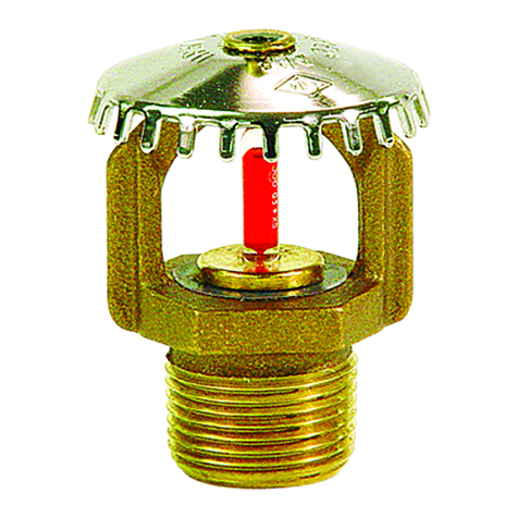
The Central Model CC1 Combustible
Concealed Sprinklers are specific ap-
plication sprinklers designed to pro-
vide protection of specific light haz-
ard combustible, as well as
non-combustible, concealed spaces
requiring sprinkler protection. The
Model CC1 Sprinklers can in some
cases allow for the use of Blazemas-
terCPVC piping within concealed
spaces requiring automatic sprinkler
protection.
When using the Model CC1 Sprin-
klers with Blazemaster CPVC pip-
ing, the system can be installed in
wood truss construction. Until re-
cently, the listing of CPVC piping for
fire protection systems did not allow
the use of CPVC piping in combusti-
ble concealed spaces requiring auto-
matic sprinkler protection. With the
extensive full scale fire testing of the
Central Model CC1 Combustible
Concealed Space Sprinklers, per-
formed at UL, Blazemaster CPVC
may now be used in the specified
combustible concealed spaces re-
quiring automatic sprinkler protec-
tion, when installed in accordance
with this Technical Data Sheet.
As an added feature, the Model CC1
Sprinklers can now be used with
steel piping for the protection of solid
wood joist construction.
The effectiveness of the Model CC1
Sprinklers, in the combustible con-
cealed spaces investigated, was
clearly evident during the full scale
fire testing for this product. Con-
cealed spaces between floors, as
well as low pitch attics are inherently
shallow. Standard spray sprinklers
by design have an umbrella like
spray pattern that poses a difficult
challenge when trying to achieve ef-
fective coverage within a shallow
space. The Model CC1 Combustible
Concealed Space Sprinklers have
addressed the difficult “above ceil-
ing” fire challenge.
Operation. The glass bulb contains
a fluid which expands when exposed
to heat. When the rated temperature
is reached, the fluid expands suffi-
ciently to shatter the glass bulb,
which allows the sprinkler to activate
and flow water.
WARNINGS
The Model CC1 Combustible Con-
cealed Space Sprinklers described
herein must be installed and main-
tained in compliance with this docu-
ment, as well as with the applicable
standards of the National Fire Protec-
tion Association, in addition to the
standards of any other authorities
having jurisdiction. Failure to do so
may impair the integrity of these de-
vices.
The owner is responsible for main-
taining their fire protection system
and devices in proper operating con-
dition. The installing contractor or
sprinkler manufacturer should be
contacted relative to any questions.
Technical
Data
Sprinkler Identification Number
SIN C1189
Approvals
UL and C-UL Listed.
(Listings and approvals only apply to
the service conditions indicated in
the Design Criteria sections.)
Maximum Working Pressure
175 psi (12.1 bar)
Pipe Thread Connection
1/2 inch NPT
Discharge Coefficient
K=3.0GPM/psi
1/2
(43.2 LPM/bar1/2)
Temperature Ratings
175°F/79°C
Finish
Natural Brass
Physical Characteristics
The Model CC1 utilizes a 3 mm di-
ameter glass bulb and a dezincifica-
tion resistant bronze alloy frame. The
frame orifice is sealed with a gas-
keted spring plate (Belleville Seal)
consisting of a beryllium nickel disc
spring that is sealed on both its in-
side and outside edges with a Tef-
lon

gasket.
Specific
Application
Combustible
Concealed
Space
Sprinklers
No. 6-3.0
Model CC1
Combustible Concealed
Space SprinklersTM
Tyco Fire Products — www.centralsprinkler.com
451 North Cannon Avenue, Lansdale, Pennsylvania 19446
Customer Services/Sales: Tel: (215) 362-0700 / Fax: (215) 362-5385
Technical Services: Tel. (800) 381-9312 / Fax: (800) 791-5500
CENTRAL CC1 3-01
OBSOLETE
Design
Criteria
Reference Figure 1
Area Of Use:
Flat concealed spaces of wood truss
construction, or flat concealed
spaces of non-combustible bar joist
construction.
Concealed Space Area:
The area of the concealed space is
not limited, however draft-curtains
must be provided at 1000 ft2(93 m2)
areas. This draft curtain shall be at
least 1/3 the depth of the wood truss
or 8 inches (200 mm), whichever is
greater and be constructed using a
material which will not allow heat to
escape through or above the draft
curtain.
Concealed Space Size:
The depth of the concealed space is
32 inches (815 mm) maximum to 12
inches (305 mm) minimum.
System Type:
Light hazard, wet pipe system.
Minimum Distance Between CC1
Sprinklers:
6 feet (3.1 m).
Minimum spacing
does not apply to any additional
sprinklers required for protection of
Blazemaster CPVC which is offset
over an obstruction.
Maximum Distance Between CC1
Sprinklers Located Just Below
Upper Deck:
10 feet (3.1 m).
Maximum Coverage Area:
100 ft2(9.3 m2)
Deflector Position:
Upright and 1-1/2 to 2 inches (40 to
50 mm) below upper deck
Minimum Distance Away From
Trusses:
4-1/2 inches (114 mm)
Remote Area:
1000 ft2(93 m2).
The remote area
does not include any additional sprin-
klers required for protection of Blaze-
master CPVC which is offset over an
obstruction.
Required Density:
0.10 gpm/ft2(4.1 mm/min).
Minimum Operating Pressure:
10 psi (0.7 bar).
Obstructions:
All obstruction criteria per NFPA for
standard spray sprinklers apply, un-
less modified by this Technical Data
Sheet.
UL Listed Use Of Blazemaster
CPVC Piping With Model CC1
Sprinklers:
Only Blazemaster CPVC product
may be used in concealed spaces re-
quiring automatic sprinklers, when
used in conjunction with Model CC1
Sprinklers. In order to use the Blaze-
master CPVC product, the bottom of
horizontally run pipe must be no
greater than 4 inches (100 mm)
above the ceiling. The CPVC piping,
can then be used to supply the
Model CC1 Sprinklers, as well as the
sprinklers below the ceiling. Unless
modified by this Technical Data
Sheet, all other guidelines of the
“Blazemaster — Installation Instruc-
tions & Technical Manual” must be
met. When using 1 inch (DN25) or
larger pipe, a hanger must be lo-
cated at the truss nearest a sprig for
purposes of restraint. If using 3/4
inch (DN19) piping, all sprigs over
12 inches (305 mm) must be later-
ally braced using methods described
in the NFPA standards.
For this listing to use the Blazemas-
ter CPVC product in concealed
spaces requiring automatic sprin-
klers, a minimum lateral distance of
18 inches (450 mm) must be main-
tained between the CPVC and the
edge of heat sources (e.g., fan mo-
tors, heat lamps, HVAC heat pump
units, etc.).
Where the CPVC must be offset up
and over an obstruction such that
the bottom of the pipe will be located
at greater than 4 inches (100 mm)
above the ceiling, additional Model
CC1 Sprinklers are to be installed as
shown in Figure 1 to protect the
Blazemaster CPVC product.
Figure 1
Wood Truss Construction or Non-Combustible Bar Joist Construction (CPVC Pipe)
Cross Section Elevation View
†
DuPont Registered Trademark
32" (815 mm) MAXIMUM
12" (450 mm) MINIMUM
4" (100 mm) MAXIMUM
FOR CPVC PIPE
2" (50 mm) MAXIMUM
1-1/2" (40 mm) MINIMUM
WHEN OFFSETTING CPVC PIPE OVER AN OBSTRUCTION,
A CC1 SPRINKLER MUST BE INSTALLED DIRECTLY ON
THE CPVC PIPE OVER THE OBSTRUCTION
CEILING
4-1/2" (114 mm) MINIMUM
FROM FACE OF WOOD TRUSS
OR TOP CHORD OF BAR JOIST
6" (150 mm)
MAXIMUM FOR
CPVC PIPE
CC1
SPRINKLER
UPPER DECK
OBSTRUCTION
PARALLEL WITH
FRAME ARMS OF
SPRINKLER MUST
BE INSTALLED
TRUSSES OR JOISTS,
NOT NECESSARILY
WITH PIPE
OBSOLETE
Design
Criteria
Reference Figure 2
Area Of Use:
Flat concealed spaces of solid wood
joist construction. The upper deck
and ceiling joists may have a maxi-
mum depth of 12 inches (300 mm)
and typical on center joist spacing of
minimum 16 inches (400 mm).
Concealed Space Area:
The area of the concealed space is
not limited, however blocking must
be provided in each upper deck and
ceiling joist channel at a maximum
32 feet (9.75 m) intervals. This block-
ing shall be installed to the full depth
of the joists and be constructed us-
ing a material which will not allow
heat to escape through or above the
blocking.
Concealed Space Size:
The minimum and maximum con-
cealed space depth is as follows:
The maximum depth of the con-
cealed space is 54 inches (1372
mm) from bottom of upper deck to
top of ceiling, and the minimum
depth is 6 inches (150 mm) from the
bottom of the upper deck joists to
the top of the ceiling joists.
System Type:
Light hazard, wet pipe system.
Minimum Distance Between CC1
Sprinklers:
6 feet (3.1 m).
Maximum Distance Between CC1
Sprinklers:
10 feet (3.1 m).
Maximum Coverage Area:
100 ft2(9.3 m2)
Deflector Position:
Upright and 1-1/2 to 2 inches (38 to
51 mm) below joists.
Remote Area:
1000 ft2(93 m2).
Required Density:
0.10 gpm/ft2(4.1 mm/min).
Minimum Operating Pressure:
10 psi (0.7 bar).
Obstructions:
All obstruction criteria per NFPA for
standard spray sprinklers apply, un-
less modified by this Technical Data
Sheet.
Use Of Blazemaster CPVC Piping
With Model CC1 Sprinklers:
Not applicable for solid wood joist
construction.
Figure 2
Solid Wood Joist Construction (Steel Pipe)
Cross Section Elevation View
54" (1372 mm)
MAXIMUM
2" (51 mm) MAXIMUM
1-1/2" (38 mm) MINIMUM
CC1 SPRINKLER
JOISTS
2x FLOOR
DECK
UPPER
CEILING
FRAMING
CEILING
FRAME ARMS OF SPRINKLER MUST BE
INSTALLED PARALLEL WITH WOOD JOISTS,
6" (152 mm)
TO
36" (914 mm)
NOT NECESSARILY WITH PIPE
Figure 4
1106 Combination
Sprinkler Wrench
Figure 3
Model CC1 Sprinkler
2-1/4"
(57.2 mm)
WRENCH
FLATS
1/2
"
NPT
1-1
/
16
"
(27.0 mm)
OBSOLETE
Installation
The Model CC1 Sprinklers must be
installed in accordance with the fol-
lowing instructions:
NOTES
The CC1 Sprinklers are to be in-
stalled upright and with their frame
arms (ref. Figure 1 or 2, as applica-
ble) parallel with the wood trusses,
top chord of the bar joist, or wood
joists, as opposed to being necessar-
ily parallel with the pipe.
Do not install any bulb type sprinkler
if the bulb is cracked or there is a
loss of liquid from the bulb. With the
sprinkler held horizontally, a small
air bubble should be present. The di-
ameter of the air bubble is approxi-
mately 1/16 inch (1.6 mm) for the
175°F/79°C temperature rating.
A leak tight 1/2 inch NPT sprinkler
joint should be obtained with a
torque of 7 to 14 ft.lbs. (9.5 to 19.0
Nm). A maximum of 20 ft.lbs. (28.5
Nm) of torque is to be used to install
sprinklers. Higher levels of torque
may distort the sprinkler inlet with
consequent leakage or impairment
of the sprinkler.
The Model CC1 Combustible Con-
cealed Space Sprinklers must only
be installed in the upright position
with the deflector parallel to the up-
per deck. With pipe thread sealant
applied to the pipe threads, use
only the 1106 Combination Sprinkler
Wrench (Figure 4) for installation of
the Model CC1 Sprinklers by apply-
ing the wrench to the sprinkler
wrench flats only.
Care &
Maintenance
The Model CC1 Sprinklers must be
maintained and serviced in accord-
ance with the following instructions:
NOTE
Before closing a fire protection sys-
tem main control valve for mainte-
nance work on the fire protection sys-
tem which it controls, permission to
shut down the affected fire protec-
tion systems must be obtained from
the proper authorities and all person-
nel who may be affected by this ac-
tion must be notified.
Sprinklers which are found to be
leaking or exhibiting visible signs of
corrosion must be replaced.
Automatic sprinklers must never be
shipped or stored where their tem-
perature will exceed 100°F/38°C and
they must never be painted, plated,
coated, or otherwise altered after
leaving the factory. Modified sprin-
klers must be replaced. Sprinklers
that have been exposed to corrosive
products of combustion, but have not
operated, should be replaced if they
cannot be completely cleaned by wip-
ing the sprinkler with a cloth or by
brushing it with a soft bristle brush.
Care must be exercised to avoid
damage - before, during, and after
installation. Sprinklers damaged by
dropping, striking, wrench twist/slip-
page, or the like, must be replaced.
Also, replace any sprinkler that has
a cracked bulb or that has lost liquid
from its bulb (ref. Installation Sec-
tion).
The owner is responsible for the in-
spection, testing, and maintenance
of their fire protection system and de-
vices in compliance with this docu-
ment, as well as with the applicable
standards of the National Fire Protec-
tion Association (e.g., NFPA 25), in
addition to the standards of any
other authorities having jurisdiction.
The installing contractor or sprinkler
manufacturer should be contacted
relative to any questions.
It is recommended that automatic
sprinkler systems be inspected,
tested, and maintained by a qualified
Inspection Service.
Limited
Warranty
Products manufactured by Tyco Fire
Products are warranted solely to the
original Buyer for ten (10) years
against defects in material and work-
manship when paid for and properly
installed and maintained under nor-
mal use and service. This warranty
will expire ten (10) years from date
of shipment by Tyco Fire Products.
No warranty is given for products or
components manufactured by com-
panies not affiliated by ownership
with Tyco Fire Products or for prod-
ucts and components which have
been subject to misuse, improper in-
stallation, corrosion, or which have
not been installed, maintained, modi-
fied or repaired in accordance with
applicable Standards of the National
Fire Protection Association, and/or
the standards of any other Authori-
ties Having Jurisdiction. Materials
found by Tyco Fire Products to be de-
fective shall be either repaired or re-
placed, at Tyco Fire Products’ sole
option. Tyco Fire Products neither as-
sumes, nor authorizes any person to
assume for it, any other obligation in
connection with the sale of products
or parts of products. Tyco Fire Prod-
ucts shall not be responsible for
sprinkler system design errors or in-
accurate or incomplete information
supplied by Buyer or Buyer’s repre-
sentatives.
IN NO EVENT SHALL TYCO FIRE
PRODUCTS BE LIABLE, IN CON-
TRACT, TORT, STRICT LIABILITY
OR UNDER ANY OTHER LEGAL
THEORY, FOR INCIDENTAL, INDI-
RECT, SPECIAL OR CONSEQUEN-
TIAL DAMAGES, INCLUDING BUT
NOT LIMITED TO LABOR
CHARGES, REGARDLESS OF
WHETHER TYCO FIRE PRODUCTS
WAS INFORMED ABOUT THE POS-
SIBILITY OF SUCH DAMAGES,
ANDINNOEVENTSHALLTYCO
FIRE PRODUCTS’ LIABILITY EX-
CEED AN AMOUNT EQUAL TO THE
SALES PRICE.
THE FOREGOING WARRANTY IS
MADE IN LIEU OF ANY AND ALL
OTHER WARRANTIES EXPRESS
OR IMPLIED, INCLUDING WAR-
RANTIES OF MERCHANTABILITY
AND FITNESS FOR A PARTICU-
LAR PURPOSE.
Ordering
Information
Ordering Procedure: When placing
an order, indicate the full product
name. Please specify the quantity,
model, style, size, and wrench, as
applicable. Refer to Price List for
complete listing of Part Numbers.
Patents: Patents are pending.
Printed in U.S.A. 3-01
OBSOLETE

Other Tyco Fire Product Irrigation System manuals

Tyco Fire Product CENTRAL ESFR-17 User manual

Tyco Fire Product

Tyco Fire Product CENTRAL ESFR-17 User manual

Tyco Fire Product CENTRAL BV4-QREC User manual

Tyco Fire Product

Tyco Fire Product CENTRAL BV4-QREC User manual

Tyco Fire Product CENTRAL ELO-231 BV User manual

Tyco Fire Product

Tyco Fire Product CENTRAL ELO-231 BV User manual

Tyco Fire Product DS-2 Series User manual

Tyco Fire Product

Tyco Fire Product DS-2 Series User manual

Tyco Fire Product CENTRAL ELO LH User manual

Tyco Fire Product

Tyco Fire Product CENTRAL ELO LH User manual

Tyco Fire Product Gem A User manual

Tyco Fire Product

Tyco Fire Product Gem A User manual

Tyco Fire Product CENTRAL GB-LO 17/32 User manual

Tyco Fire Product

Tyco Fire Product CENTRAL GB-LO 17/32 User manual

Tyco Fire Product Star Pulsar S160 User manual

Tyco Fire Product

Tyco Fire Product Star Pulsar S160 User manual

Tyco Fire Product Gem TFP1 User manual

Tyco Fire Product

Tyco Fire Product Gem TFP1 User manual

Tyco Fire Product CENTRAL ELO-231 User manual

Tyco Fire Product

Tyco Fire Product CENTRAL ELO-231 User manual

Tyco Fire Product Star Galaxy SGQR User manual

Tyco Fire Product

Tyco Fire Product Star Galaxy SGQR User manual

Tyco Fire Product Star E User manual

Tyco Fire Product

Tyco Fire Product Star E User manual

Tyco Fire Product Star S190 User manual

Tyco Fire Product

Tyco Fire Product Star S190 User manual

Tyco Fire Product Star PH-5 User manual

Tyco Fire Product

Tyco Fire Product Star PH-5 User manual

Tyco Fire Product Gem FR-1 User manual

Tyco Fire Product

Tyco Fire Product Gem FR-1 User manual

Tyco Fire Product CENTRAL BVR User manual

Tyco Fire Product

Tyco Fire Product CENTRAL BVR User manual

Tyco Fire Product CC1 User manual

Tyco Fire Product

Tyco Fire Product CC1 User manual

Tyco Fire Product CENTRAL ESFR-1 User manual

Tyco Fire Product

Tyco Fire Product CENTRAL ESFR-1 User manual

Tyco Fire Product Star Galaxy SG-R User manual

Tyco Fire Product

Tyco Fire Product Star Galaxy SG-R User manual

Tyco Fire Product CENTRAL EC-25 User manual

Tyco Fire Product

Tyco Fire Product CENTRAL EC-25 User manual

Tyco Fire Product CENTRAL ELO-16 GB FR User manual

Tyco Fire Product

Tyco Fire Product CENTRAL ELO-16 GB FR User manual

Tyco Fire Product CENTRAL WS User manual

Tyco Fire Product

Tyco Fire Product CENTRAL WS User manual

Tyco Fire Product Gem F960 User manual

Tyco Fire Product

Tyco Fire Product Gem F960 User manual

Tyco Fire Product Gem AQUARIUS F990 User manual

Tyco Fire Product

Tyco Fire Product Gem AQUARIUS F990 User manual

Popular Irrigation System manuals by other brands

Viking VK503 Technical data

Viking

Viking VK503 Technical data

Irrigatia SOL-C12 Installation and operation

Irrigatia

Irrigatia SOL-C12 Installation and operation

Toro 53707 installation guide

Toro

Toro 53707 installation guide

Tyco ESFR-1 manual

Tyco

Tyco ESFR-1 manual

Viking FREEDOM VK486 Technical data

Viking

Viking FREEDOM VK486 Technical data

Viking HQR-2 Technical data

Viking

Viking HQR-2 Technical data

Chapin 4701 Assembly / operation instructions / parts

Chapin

Chapin 4701 Assembly / operation instructions / parts

Mondo Verde IRA03 quick start guide

Mondo Verde

Mondo Verde IRA03 quick start guide

Tyco Ultra K17 quick start guide

Tyco

Tyco Ultra K17 quick start guide

Nelson F75 Big Gun Operation & maintenance instructions

Nelson

Nelson F75 Big Gun Operation & maintenance instructions

CENTRAL GB manual

CENTRAL

CENTRAL GB manual

Tyco Fire Protection Products ESFR-17 manual

Tyco Fire Protection Products

Tyco Fire Protection Products ESFR-17 manual

Reliable J168 instructions

Reliable

Reliable J168 instructions

Autopot 80Pot XL Set-up guidelines

Autopot

Autopot 80Pot XL Set-up guidelines

Shield SD1010 manual

Shield

Shield SD1010 manual

Hunter I-20 ULTRA manual

Hunter

Hunter I-20 ULTRA manual

Orbit YARD ENFORCER Assembly instructions

Orbit

Orbit YARD ENFORCER Assembly instructions

Viking VK510 Technical data

Viking

Viking VK510 Technical data

manuals.online logo
manuals.online logoBrands
  • About & Mission
  • Contact us
  • Privacy Policy
  • Terms and Conditions

Copyright 2025 Manuals.Online. All Rights Reserved.