Passing the RJ45 connector through the grommet
(continued)
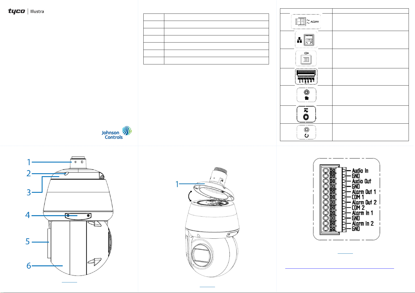
Figure 7
Inserting or removing the micro SD card
1. Remove the two screws located on the micro SD card cover (4)
(Figure 1),
Figure 4
Inserting or removing the micro SD card (continued)
2. Carefully pull open the cover to access the SD card slot (1) (Figure
4) and insert (or remove) the micro SD card into (or from) the
camera.
Note: It is advised that you reboot the camera after inserting the
micro SD card.
3. Secure the two screws located on the micro SD card cover.
Note: The USB cable connection slot (2) (Figure 4) for Wi-Fi
configuration is also located under the micro SD card cover.
The Wi-Fi option allows wireless configuration of the camera at the
point of install in conjunction with the Illustra Tools app (Illustra Wi-
Fi dongle required).
Connecting the wires
This unit supports one of the following options as power supply:
1. Connect a power source.
AC24V wired to connector and separate RJ45 Ethernet.
OR
PoE through RJ45 connector. The Outdoor unit operates with
IEEE 802.3bt (71W max).
2. Connect any optional audio or digital inputs or outputs.
Note: After connecting all cables ensure that the two screws on
the top cover are securely attached to maintain the waterproof
seal.
Installing the rubber cable seal in to the NPT pendant cap
1. Securely place the rubber cable seal (2) (Figure 5) into the
pendant cap (3) (Figure 5).
Figure 5
2. Place the mount adaptor (1) (Figure 5) on to the NPT pendant cap
(3) (Figure 5) and align the holes on the mount adaptor with the
holes on the NPT pendant cap.
3. Insert the three security screws into the three holes and use the
Torx security L-Key to securely attach the screws and the mount
adaptor to the NPT cap.
Installing the mount adaptor on to the NPT pendant cap
(continued)
Note: To maintain the waterproof seal only pierce holes that are
required for the installation.
Passing the RJ45 connector through the grommet
1. Remove the plug from the grommet (1) (Figure 6) by pulling the
stub (2) (Figure 6) to create a hole in the grommet.
Figure 6
2. Insert the RJ45 cable connector (1) (Figure 7) into the insert tool
(2) (Figure 7).
3. Push the insert tool and cable through the grommet hole (3)
(Figure 7).
4. Remove the insert tool from the RJ45 connector and pass the
cable through the NPT cap (4) (Figure 7).
Warnings
1. Installation and service should be performed only by qualified and
experienced technicians and comply with all local codes and rules to
maintain your warranty.
2. Wipe the camera with a dry soft cloth. For tough stains, slightly apply
with diluted neutral detergent and wipe with a dry soft cloth.
3. Do not apply benzene or thinner to the camera, which may cause
the surface of the unit to be melted or lens to be fogged.
4. To meet EU EMC immunity requirements for security equipment the
mains power for equipment powering this unit should be backed up
by an uninterruptible power supply.
5. Avoid operating or storing the unit in the following locations:
a. Near fluorescent lamps or objects with reflections.
b. Under unstable or flickering light sources.
© 2021 Johnson Controls. All rights reserved. JOHNSON CONTROLS,
TYCO and ILLUSTRA are trademarks and/or registered trademarks.
Unauthorized use is strictly prohibited.