Tycon Power Systems UPSPro UPS-STL48 User manual

UPS-STL48
UPSPro™ Backup
Power System
▫Wireless Base Stations
▫Surveillance Cameras
▫Remote Gate Control
▫Electric Fence
▫Up to 200W loads
Congratulations! on your purchase of the UPSPro™ outdoor
backup power system. Please take a moment to review this Qwik
Install Guide before assembly or battery installation.
DANGER! Avoid Powerlines!
You Can Be Killed!
When following the instructions in this guide take extreme care
to avoid contact with overhead power lines, lights and power circuits.
Contact with power lines, lights or power circuits may be fatal. We rec-
ommend to install no closer than 20 feet to any power lines.
Safety: For your own protection, follow these safety rules.
▫Perform as many functions as possible on the ground
▫Do not attempt to install on a rainy, windy or snowy day or if
there is ice or snow accumulation at the install site or if the
site is wet.
▫Make sure there are no people, pets, etc. below when you are
working on a roof or ladder.
Recommended Tools: Phillips & Flat Screwdriver,
17/13/10mm wrench, 8mm nut driver
Please help preserve the environment and return
used batteries to an authorized depot

2
Qwik Install
STEP 1: Prepare the enclosure: Install DIN rail (if required) to door
using two phillips head screws. Install just the top mounting bracket to
the enclosure using two 8mm bolts.
NOTE: It takes two persons to mount
the enclosure to a pole. The standard U
-Bolt mounting accommodates a pole
up to 4” diameter. Multiple pole straps
can be used for extra strength or if
mounting to a larger diameter pole to
11”.
STEP 2: Install the bottom bracket
and stabilizer bracket to the pole using
U-Bolt and/or Pole Straps.The stabilizer
bracket is used an an aid to mounting
and additional support when mounted.
STEP 3: Lift the enclosure and place
it on the stabilizer bracket. Connect the
top bracket to the pole using U-Bolt
and/or Pole Straps.
STEP 4: Attach The two 8mm bolts that
hold the bottom bracket to the enclo-
sure. Make sure all bolts are tight. (8-15
ft lbs)
STEP 5: Install the three wire feed-
thru cable glands in the holes in the
bottom of the enclosure. If one or more
of the cable glands will not be used,
just cut a short piece of wire and tighten
in the cable gland.
NOTE: The bottom plate can be re-
moved from the enclosure if you need
to add some additional feedthru. (ex;
conduit connection)
STEP 6: Install the batteries in the enclosure.
There must be at least four batteries connected in
series to create 48V. If eight batteries are used con-
nect first four in series and second four in series then
parallel the two banks. (See wiring diagram).
Note: The enclosure has slot features that can be
used to strap the batteries if desired. Tycon has vel-
cro straps available. It takes two straps per battery.

3
STEP 7: Before attaching the battery cables to the batteries, first
remove the battery cable fuse. This will prevent accidental short circuit.
Connect the battery cables to the batteries. Connect the Temperature
probe from the controller to any of the battery terminals. The tempera-
ture sensing lug is just a mechanical connection so it doesn’t matter
which terminal it is connected to (+ or -). The probe has no polarity
when connecting to the controller.
STEP 8: Install the controller and AC/DC power supply by hanging
on welded DIN rails on either side of enclosure between batteries and
door. Remove the large green connector from the controller. Connect
the battery cables to the controller BAT+ and BAT– inputs. Connect the
thermostatically controlled fan to the controller BAT+ and BAT– inputs.
Note: Do not re-install the large Green connector until all wiring is com-
plete and you are ready to power up the system.

4
STEP 9: Set the AC/DC power supply input voltage to either
115VAC or 230VAC by moving the screw attached cable to the appro-
priate position.
WARNING! Make sure this is set correctly before connecting the
AC line or you will damage the power supply.
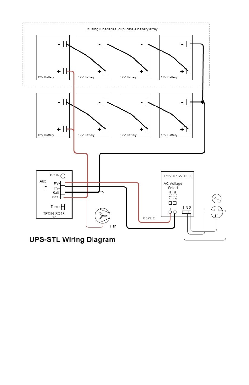
STEP 10: Connect the Output + from the power supply to the PV+
position on the large Green connector. Connect the Output - from the
power supply to the PV - on the large Green connector.
WARNING! Be sure to make sure the polarity is correct before
powering the system or you will damage the controller.
STEP 11: Connect your AC input wires to the power supply at the
screw terminal labeled LNG. L=Load, N=Neutral, G=Ground
STEP 12: Connect your equipment to the controller and finish up
any wiring to your equipment then re-install the fuses in the battery ca-
bles.
STEP 13: Plug the large Green connector to the controller. The
Battery Charging LED will light for about 60seconds when power is first
applied, then there will be no LED lit until some changes are made to
the controller web interface.
STEP 14: Turn on AC power to the AC/DC power supply. You
should see the Battery Charging LED turn on. The LED will be steady
state when the batteries are charging and will be flashing when the con-
troller is in float charge mode.
STEP 15: Connect the controller to your network through one of
the switch ports, preferably port 7. The default IP address is
192.168.1.6 The unit may also get an IP address from a DHCP server.
We have a free discovery tool available at http://tyconsystems.com/
index.php/support/tpdin-firmware This tool will find the controller no
matter what IP address it is on even across subnets.
STEP 16: Once you open the web interface, you can set the volt-
age for each port including the Aux port and you can turn the power on
and off to each port.
WARNING! Be careful not to turn on the power to the port that
your network is connected to. If the connected device is not a PoE
compatible device it might be damaged by the PoE power on the
port.
STEP 17: Refer to the controller user guide for more info on setup and
use of the controller features..

5
TECH CORNER
Additional Information you may find useful
1. CONTROLLER: The controller will turn off all loads when the battery
voltage falls below a set value. This value can be set in the user inter-
face. This low voltage disconnect function is needed to preserve the life
of the batteries.
2. MAXIMUM LOAD: The maximum load supported by the control-
ler is 200W. If the load is exceeded the controller will shut down all
loads and display an error condition. It will automatically reset after the
load falls below 200W.
3. OUTPUT VOLTAGE: The output voltage from the controller on
all ports can be set individually to 48V or 24V in the user interface.
4. VENTING: The enclosure has vents in the upper back of the enclo-
sure and a thermostatically controlled fan and vent in the bottom of the
enclosure. Fan airflow should be toward inside of enclosure.
SPECIFICATIONS Subject to change without notice
UPS-STL48-50 UPS-STL48-100
Load Voltage 24V/48V Selectable 24V/48V Selectable
Max Load 200W 200W
VAC Input +/- 10% 115 / 230VAC user selectable
VAC Input Current 12A @ 115VAC ; 6A @ 230VAC Max
Battery Capacity 200Ah 400Ah
Battery Type Non-Spillable Sealed Lead Acid —AGM
Battery Life 5 Years 5 Years
Over-discharge protec-
tion 45.8V to 47.8 – settable in web interface
Output Ports Qty 7 Gigabit Passive PoE 24/48V (Qty 3 @
35W and Qty 4 @ 15W)
Aux Output 24V or 48V @ 2.25A Max;
Selectable via Web Interface
Self Consumption 3.5W Typ 3.5W Typ
Enclosure Type Steel—STL Steel—STL
Operating Temp -30°C to +60°C (-22°F to 140°F)

6
5. BATTERY MAINTENANCE: The batteries used in the UPSPro sys-
tems don’t require any maintenance. They should last up to 5 years in
normal use. Note: Never store batteries for any length of time in a dis-
charged state or it will kill the battery.
6. BATTERY OVERDISCHARGE: We highly recommend hooking
all equipment loads to the controller voltage output. This output will dis-
connect the load if the battery voltage drops below the set voltage and
this will protect the battery from over-discharge. If batteries get com-
pletely discharged because the equipment was connected directly to
the battery, you will reduce the battery life. Discharged batteries will
freeze at very low temperatures.
7. ACCESSORIES: Tycon also offers a variety of voltage conver-
sion products to meet almost any need. Just visit tyconsystems.com for
more info.
Limited Warranty
The UPSPro™ products are supplied with a limited 24 month warranty
which covers material and workmanship defects. This warranty does
not cover the following:
▫Parts requiring replacement due to improper installation, misuse,
poor site conditions, faulty power, etc.
▫Lightning or weather damage.
▫Physical damage to the external & internal parts.
▫Products that have been opened, altered, or defaced.
▫Water damage for units that were not mounted according to user
manual.
▫Usage other than in accordance with instructions and the normal
intended use.
NOTES

7

8
8000050 Rev 1 UPS-STL UPSPro™ Qwik Install Guide
Table of contents
Other Tycon Power Systems Power Supply manuals