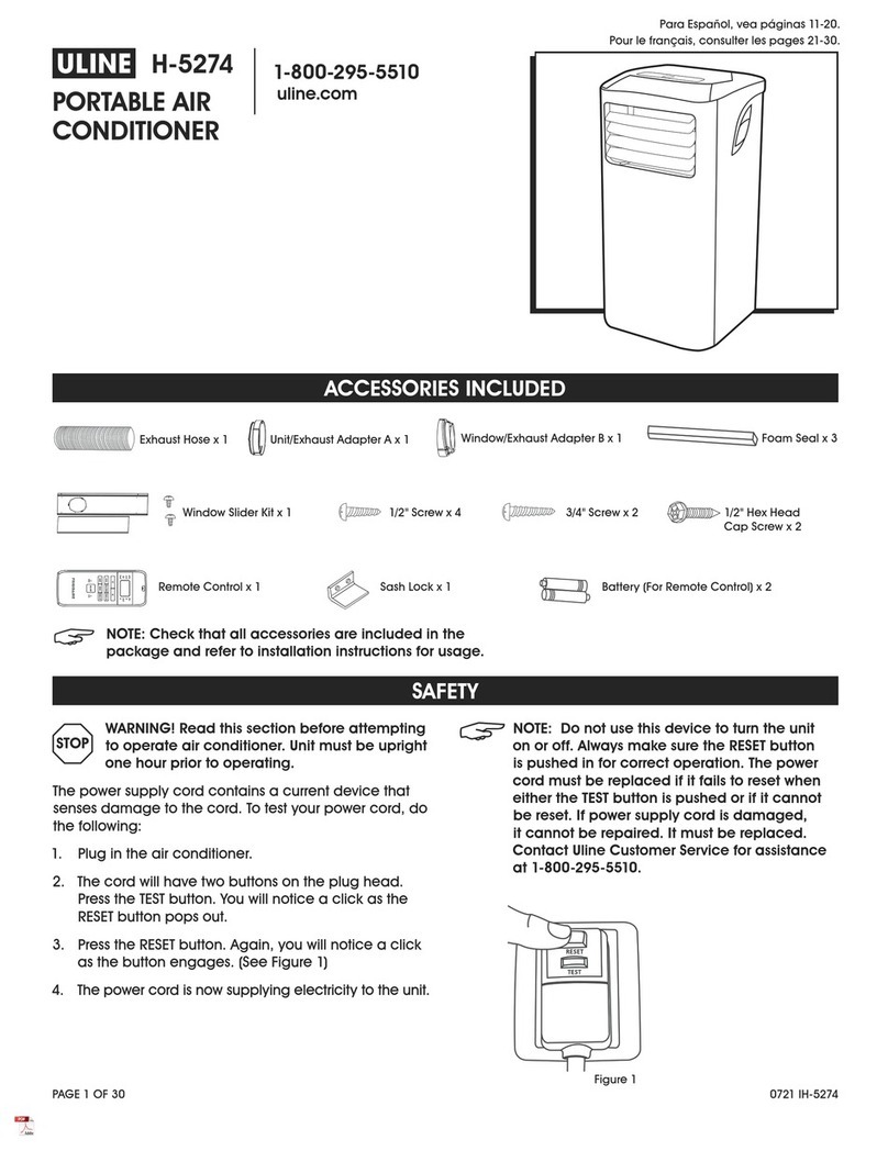
U-Line H-5200 User manual

PAGE 1 OF 30 0721 IH-5200
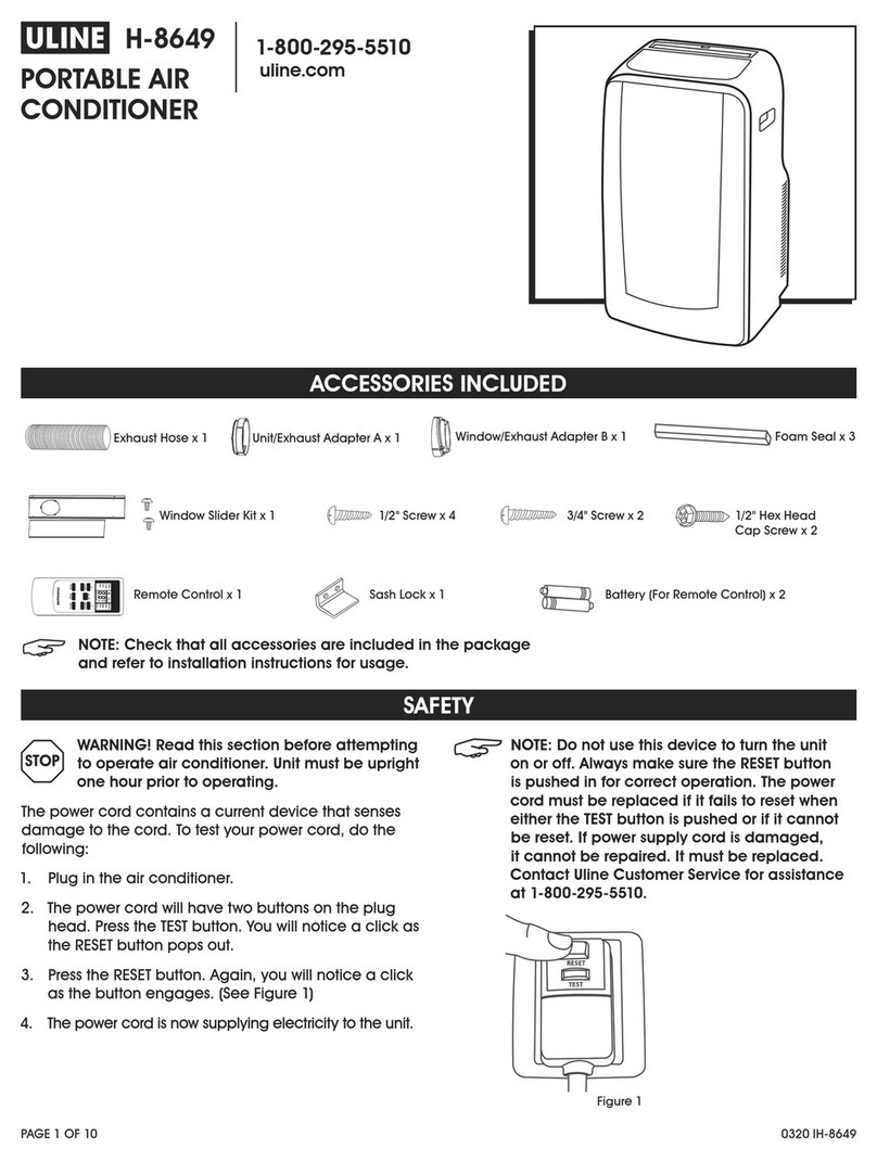
H-5200
PORTABLE AIR
CONDITIONER
1-800-295-5510
uline.com
WARNING! Read this section before attempting
to operate air conditioner. Unit must be upright
one hour prior to operating.
The power cord contains a current device that senses
damage to the cord. To test your power cord, do the
following:
1. Plug in the air conditioner.
2. The power cord will have two buttons on the plug
head. Press the TEST button. You will notice a click as
the RESET button pops out.
3. Press the RESET button. Again, you will notice a click
as the button engages. (See Figure 1)
4. The power cord is now supplying electricity to the unit.
NOTE: Do not use this device to turn the unit
on or off. Always make sure the RESET button
is pushed in for correct operation. The power
cord must be replaced if it fails to reset when
either the TEST button is pushed or if it cannot
be reset. If power supply cord is damaged,
it cannot be repaired. It must be replaced.
Contact Uline Customer Service for assistance
at 1-800-295-5510.
SAFETY
ACCESSORIES INCLUDED
Figure 1
Exhaust Hose x 1
NOTE: Check that all accessories are included in the package
and refer to installation instructions for usage.
Unit/Exhaust Adapter A x 1 Window/Exhaust Adapter B x 1 Foam Seal x 3
Battery (For Remote Control) x 2Sash Lock x 1Remote Control x 1
Window Slider Kit x 1 1/2" Screw x 4 1/2" Hex Head
Cap Screw x 2
3/4" Screw x 2
Para Español, vea páginas 11-20.
Pour le français, consulter les pages 21-30.

PAGE 2 OF 30 0721 IH-5200
NORMAL SOUNDS
UNIT DESCRIPTION
Today’s high efficiency
compressors may have a
high-pitched chatter during
the cooling cycle.
Unit may vibrate and make noise
because of uneven floor.
At the front of the unit, you may
hear the sound of rushing air
being moved by the fan.
“Gurgling or hissing” noise may be
heard due to refrigerant passing
through evaporator during normal
operation.
Sound of Rushing Air
Gurgle/Hiss
High-pitched Chatter
Vibration
Control Panel
Caster
Remote Control
Room Air Discharge
Carrying Handle
(Both Sides)
Remote Signal
Receiver
Exhaust
Air Outlet
Air Intake
Dehumidifying
Drain Outlet
Bottom Tray
Drain Outlet
Air Intake

PAGE 3 OF 30 0721 IH-5200
INSTALLATION
EXHAUSTING HOT AIR
In cooling mode, the appliance must be placed close
to a window or opening so that the warm exhaust air
can be ducted outside.
First, position unit on a flat floor. Make sure there is a
minimum of 12" clearance around the unit and that it is
within the vicinity of a single circuit outlet power source.
1. Extend either side of the hose. (See Figure 2)
2. Screw the hose onto adapter A. (See Figure 3)
3. Extend the other side of the hose and screw it to
adapter B. (See Figure 4)
4. Slide the assembly onto unit. (See Figure 5)
5. Affix adapter B into the window slider kit and seal.
(See Figures 6 and 7)
The hose can be extended from its original length of
15" up to 59", but it is the best to keep the length to the
minimum required. Also, make sure that the hose does
not have any sharp bends or sags. (See Figure 8)
Extend the side of hose
Slide onto
Window Slider Kit
Minimum: 26.6"
Maximum: 48.5"
Vertical
Window
Window Slider Kit
Minimum: 26.6"
Maximum: 48.5"
Horizontal
Window
Figure 6
Figure 7
Figure 3
Figure 2
Figure 4
Figure 5
Figure 8

PAGE 4 OF 30 0721 IH-5200
INSTALLATION CONTINUED
INSTALLATION IN A DOUBLE HUNG
SASH WINDOW
1. Cut the adhesive-type foam seals to the proper
lengths and attach them to the window and sill.
(See Figure 9)
2. Open the lower sash and place the window slider kit
on the window sill. (See Figure 10) Adjust the length
of the window slider kit according to the width of
window. Screw down the two screws on the window
slider kit. (See Figure 10) Cut the adjustable window
slider kit if the width of window is less than 26.6".
(See Figure 11)
3. Close the lower sash securely against the window
slider kit. (See Figure 12)
4. Drive two 1/2" screws to secure the window slider kit
to the lower sash. (See Figure 12)
5. Secure the window slider kit to the window sill.
(See Figure 12)
a. For wooden windows, use 3/4" screws for securing
.
b. For Vinyl-Clad windows, use 1/2" hex head cap
screws for securing.
6. To secure lower sill in place, attach sash lock with
1/2" screw as shown. (See Figure 13)
NOTE: It is difficult to lock vinyl-clad windows
with the sash, so lock by window itself.
7. Cut the foam seal to an appropriate length and seal
the open gap between the top window sash and
outer window sash, as shown. (See Figure 14)
Foam Seals
(Adhesive T
ype)
Window Slider Kit
Window Sill
26.6"-48.5"
Screws
Cut this side to fit your window
Fig ure 11
Figure 10
Figure 9
Window Slider Kit
Window Sill
1/2" Screws
3/4" Screws or
1/2" Hex Head
Cap Screws Figure 12
Figure 13
Foam Seal
Figure 14

PAGE 5 OF 30 0721 IH-5200
INSTALLATION IN A SLIDING SASH WINDOW
1. Cut the adhesive-type foam seals to the proper
lengths and attach them to the window frame.
(See Figure 15)
2. Open the window sash and place the window slider
kit on the window sill. (See Figure 16) Attach the
window slider kit to the window sill. Adjust the length
of the window slider kit according to the height
of the window. Screw down the two screws on the
window slider kit. (See Figure 16) Cut the adjustable
window slider kit if the height of the window is less
than 26.6". (See Figure 17)
3. Close the sliding sash securely against the window
slider kit. (See Figure 18)
4. Secure the window slider kit to the window sill.
(See Figure 18)
a. For wooden windows, use 3/4" screws for securing.
b. For Vinyl-Clad windows, use 1/2" hex head cap
screws for securing.
5. Cut the foam seal to an appropriate length and seal
the open gap between the sliding sash and outer
window sash. (See Figure 19)
6. To secure the sliding sash in place, attach sash lock
with 1/2" screw. (See Figure 20)
INSTALLATION CONTINUED
Foam Seals
(Adhesive Type)
Screws
26.6"-48.5"
Window Sill Window Slider Kit
Cut This Side to Fit Window
Figure 16
Figure 17
Figure 15
Foam Seal
Screws
26.6"-48.5"
Window Sill Window Slider Kit
Figure 18
Figure 19
Figure 20

PAGE 6 OF 30 0721 IH-5200
AIR CONDITIONER FEATURES
CONTROL PANEL
REMOTE CONTROL
Swing
Button
Activates
Timer
Adjusts
Temperature
or Time
Sets Mode Sets Fan
Speed
Sleep
Mode
Turns Unit
On or Off
Check Filter
Reset Button
Displays
Temperature/Time
Mode Indication
Mode Selector
Fan Speed Selection
Fan Speed Selector
Temperature Buttons
On/off Button
Timer Buttons
Reset and Lock
Pin Buttons
Swing Button
Sleep Button
Battery Size: AAA
WARNING! Do not mix old and new batteries. Do not mix alkaline, standard (carbon-zinc) or rechargeable
(nickel-cadmium) batteries. This device complies with Part 15 of the FCC Rules. Operation is subject to the
following two conditions: This device may not cause harmful interference. This device must accept any
interference received, including interference that may cause undesired operation.
NOTE: The RESET button is depressed when you want to return to the initial factory settings. The LOCK
button is depressed to lock the keypad so the settings cannot be changed. The key symbol will appear in
the display of the remote control when locked. Depress the LOCK button again to release. Use a small pin
to depress these buttons.

PAGE 7 OF 30 0721 IH-5200
OPERATION
COOLING MODE
In this mode, the exhaust adapter hose must be used:
1. Press the MODE button until the "cool" indicator lights up.
2. Press the " " temperature buttons for desired settings.
3. Press the FAN SPEED button for desired fan speed.
HEATING MODE
In this mode, you do not need to use the exhaust
adapter hose:
1. Press the MODE button until the "heat" indicator lights up.
2. Press the " " temperature buttons for desired heat
settings.
DRY MODE
In this mode, you do not need to use the exhaust
adapter hose, but the water collected must be
discharged. See Drainage section on page 8.
1. Press the MODE button until the "dry" indicator lights up.
2. The fan will run at low speed and the display will
show the room temperature.
3. Keep doors and windows closed for best effect.
AUTO MODE
Always have the exhaust hose attached in this mode.
When you set the air conditioner to auto mode, it
will automatically select cooling, heating or fan only
operation depending on what temperature you have
selected and the room temperature. The air conditioner
will control room temperature automatically based on
temperature set by you. Under auto mode, you cannot
select the fan speed.
FAN MODE
In this mode, there is no need to use the exhaust hose
or drainage hose. However, to remove stale or smoky
air from the room, hook up the duct accessories as
described in the Exhausting Hot Air section on page 3.
1. Press the MODE button until the "fan" indicator lights up.
2. Press the FAN SPEED button to choose the desired fan
speed.
3. The fan will run at the selected speed and the
display will show the room temperature.
TIMER OPERATION
You can set both delay stop and delay start while unit
is in ON or OFF position. When unit is in ON position, first
press TIMER button to go to delay stop setting, then
"timer off" light will illuminate. Tap or hold the UP arrow
( ) or the DOWN arrow ( ) to change delay stop timer
at 0.5 hour increments up to 10 hours, then at 1 hour
increments up to 24 hours. Then, press the TIMER button
to confirm the setting (the control will confirm the setting
automatically after 5 seconds) and go to delay start
setting. Use the same way as above to set the delay
start timing. If you do not need to set delay start, press
the TIMER button again to exit. After 5 seconds, the
control will automatically change the display back
to previous temperature display. To check remaining
time, press the TIMER button. The delay start operation
automatically selects mode, temperature and fan
speed the same as last operation set.
When unit is in OFF position, press TIMER button to first go
to delay start setting, then "timer on" light will illuminate.
Set the delay start and delay stop timing the same way
as above.
To cancel the timer setting, simply tap the ( ) or ( )
button to change the timing to 0.0.
SLEEP OPERATION
In this mode, the selected temperature will increase
by 2°F 30 minutes after the mode is selected. The
temperature will then increase by another 2°F after
an additional 30 minutes. This new temperature will
be maintained for 7 hours before it returns to the
originally selected temperature. This ends the sleep
mode and the unit will continue to operate as originally
programmed. The sleep mode program can be
cancelled at any time during operation by again
pressing the sleep button.
NOTE: This feature is unavailable under fan or
dry modes.
NOTE: The following instructions explain the control panel, and they can be used for the remote control also.
<
<
<
<
<
<
<
<

PAGE 8 OF 30 0721 IH-5200
OPERATION CONTINUED
SWING OPERATION
When you turn on the unit, the louver will swing and stop
at a certain angle. You can press the SWING button
to let the louver swing automatically. Press the SWING
button again when you want the louver stopped at
desired angle.
CHECK FILTER FEATURE
This feature is a reminder to clean the air filter (see Care
and Cleaning) for more efficient operation. The "filter"
indicator will illuminate after 250 hours of operation.
To reset after cleaning the filter, press the FILTER RESET
button and the light will go off.
FAULT CODE
If the display reads "EA," the room
temperature sensor has failed. Contact
Uline Customer Service at 1-800-295-5510.
If the display reads "ES," the evaporator
temperature sensor has failed. Contact
Uline Customer Service at 1-800-295-5510.
If the display reads "E4," the display
panel communication has failed.
Contact Uline Customer Service at
1-800-295-5510.
If the display reads "P1," bottom tray is
full. Carefully move the unit to a drain
location, remove the bottom drain plug
and let the water drain away. Restart
the machine until the "P1" symbol
disappears. If error repeats, call Uline
Customer Service at 1-800-295-5510.
DRAINAGE
During the dehumidifying mode, you will need a
garden hose (sold separately) to drain the condensate
from the unit. Remove the rubber stopper from the hose
connector. (See Figure 21)
The hose may then:
a. Discharge into a drain that is lower than the unit.
b. Be connected to a condensate pump (sold
separately).
Garden Hose
Remove the
Supplied
Rubber Stopper
Figure 21

PAGE 9 OF 30 0721 IH-5200
OPERATION CONTINUED
ADDITIONAL INFORMATION
• The "cool" circuit has an automatic three minute
time-delayed start if the unit is turned off and on
quickly. This prevents overheating of the compressor
and possible circuit breaker tripping. The fan will
continue to run during this time.
• The control will maintain the set temperature within
2°F, between 62°F and 86°F (17°C and 30°C).
• The control panel is capable of displaying
temperature in Fahrenheit or Celsius. To convert from
one to the other and back, press and hold the "Temp" Up
( ) and Down ( ) buttons together for three seconds.
• There is a two second delay for the compressor
shutting down when selecting fan only/heat. This
covers the possibility of rolling through to another
mode.
• After a power outage, the unit will memorize the last
setting and return the unit to the same setting once
power is restored.
Clean air conditioner occasionally to keep it looking new. Be sure to
unplug the unit before cleaning to prevent shock or fire hazards.
AIR FILTER CLEANING
• This unit has two filters: filter A and B. Grasp the upper panel tab
and take off filter A behind the grill of the back panel.
(See Figure 22)
• Remove the lower filter B by loosening the screws. Take down the
air inlet grill, then remove the air filter.
(See Figures 23 and 24)
• Wash the filters using liquid dish washing detergent and warm
water. Rinse filters thoroughly. Gently shake excess water from the
filters. Be sure filters are thoroughly dry before replacing.
• Instead of washing, you may vacuum the filters clean.
CABINET CLEANING
• The cabinet and front may be dusted with an oil-free cloth or
washed with a cloth dampened in a solution of warm water and
mild liquid detergent. Rinse thoroughly and wipe dry.
• Never use harsh cleaners, wax or polish on the cabinet front.
• Be sure to wring excess water from the cloth before wiping around
the controls. Excess water in or around the controls may damage
the air conditioner.
WINTER STORAGE
If you plan to store the appliance during the winter, cover it with plastic
or return it to its carton.
<
<
CARE AND CLEANING
Filter A
Remove Three
Screws and
Take the Air
Intake Grill Down
Remove Filter B
Out From Grill
Filter B
Figure 22
Figure 23
Figure 24

PAGE 10 OF 30 0721 IH-5200
TROUBLESHOOTING
OPERATING ISSUE CAUSES RECOMMENDATIONS
Air conditioner will not operate. Wall plug disconnected.
Plug current device tripped.
House fuse blown or circuit breaker tripped.
Control is off.
P1 appears in the display window.
Shut off in Heat mode.
Room Temperature lower than the set temperature
(Cool Mode).
Room Temperature higher than the set temperature
(Heat Mode).
Push plug firmly into wall outlet.
Press the RESET button.
Replace fuse with time-delay type or reset circuit
breaker.
Turn Control on and set to desired setting.
Drain water as described in Drainage section on
page 8.
When the air outlet exceeds 158° F (70° C), the
automatic heat protection engages. Remove any
blockages and let appliance cool down.
Reset the temperature.
Air from unit does not feel cold
enough.
Room temperature below 60°F (16°C).
Compressor shut off by changing modes.
Cooling may not occur until room temperature rises
above 60°F (16°C).
Reset to a lower temperature.
Wait approximately three minutes and listen for
compressor to restart when set in cool mode.
Air conditioner cooling,
but room is too warm – ice
forming on cooling coil
behind front.
Outdoor temperature below 60°F (16°C).
Air filter may be dirty.
Temperature is set too low for nighttime cooling.
Exhaust duct not connected or blocked.
Cooling may not occur until room temperature rises
above 60°F (16°C).
Clean filter. Refer to Care and Cleaning section on
page 9. To defrost, set to fan only mode.
To defrost the coil, set to fan only mode. Then, set
temperature to a higher setting.
See Exhausting Hot Air section on page 3.
Air conditioner cooling,
but room is too warm – no
ice forming on cooling coil
behind front.
Dirty air filter – air restricted.
Temperature is set too high.
Air directional louvers positioned improperly.
Front of unit is blocked by drapes, blinds or furniture,
which restrict air distribution.
Doors, windows or registers open and cold air
escapes.
Unit recently turned on in hot room.
Clean air filter. Refer to Care and Cleaning section on
page 9.
Set temperature to a lower setting.
Position louvers for better air distribution.
Clear blockage in front of unit.
Close doors, windows or registers.
Allow additional time to remove stored heat from walls,
ceiling, floor and furniture.
Air conditioner turns on and off
rapidly.
Dirty air filter – air restricted.
Outside temperature extremely hot.
Clean air filter.
Set fan speed to a faster setting to bring air through
cooling coils more frequently.
Noise when unit is cooling. Air movement sound.
Vibration from uneven floor.
This is normal. If too loud, set to lower fan setting.
Move or support appliance correctly on even surface.
Room too cold. Set temperature too low. Increase set temperature.
Room too hot. Set temperature too high. Lower set temperature.
1
-800-295-551
0
uline.com

PAGE 11 OF 30 0721 IH-5200
AIRE
ACONDICIONADO
PORTÁTIL
800-295-5510
uline.mx
H-5200
¡ADVERTENCIA! Lea esta sección antes de
intentar poner en funcionamiento el aire
acondicionado. La unidad debe colocarse en
posición vertical una hora antes de ponerla en
funcionamiento.
El cable eléctrico contiene un dispositivo de corriente
que detecta cualquier daño al cable. Para probar el
cable eléctrico, haga lo siguiente:
1. Enchufe el aire acondicionado.
2. El cable eléctrico tendrá dos botones en la cabeza
del enchufe. Presione el botón TEST. Notará un clic al al
activarse el botón de RESET.
3. Presione el botón RESET. Nuevamente usted notará
un clic al activarse el botón. (Vea Diagrama 1)
4. El cable eléctrico suministra ahora electricidad a
la unidad.
NOTA: No utilice este dispositivo para encender
o apagar la unidad. Asegúrese siempre de
que el botón RESET esté presionado para un
funcionamiento adecuado. El cable electrico
deberá ser reemplazado si no se puede reiniciar
ya sea cuando se presiona el boton TEST o en
caso de que no se pueda reiniciar. Si el cable
de suministro de electricidad está dañado,
no debe repararse. Debe reemplazarse.
Comuníquese con Servicio a Clientes de Uline
para obtener asistencia
llamando al 800-295-
5510.
SEGURIDAD
ACCESORIOS INCLUIDOS
Diagrama 1
NOTA: Compruebe que todos los accesorios están incluidos en el paquete
y consulte las instrucciones de instrucciones de instalación para el uso.
1 Manguera
de Escape
1 Adaptador A para
Unidad/Escape
1 Adaptador B para
Ventana/Escape
2 Baterías (Para el
Control Remoto)
1 Seguro para
Hoja de Ventana
1 Control Remoto
1 Kit Deslizante
para Ventana
4 Tornillos
de 1/2"
2 Tornillos
de Cabeza
Hexagonal de 1/2"
2 Tornillos
de 3/4"
3 Sellos de
Espuma

PAGE 12 OF 30 0721 IH-5200
SONIDOS NORMALES
DESCRIPCIÓN DE LA UNIDAD
Los compresores de alta
eficiencia de la actualidad
pueden tener un sonido
agudo durante el ciclo
de enfriamiento.
La unidad puede vibrar y hacer ruidos
a causa de un piso irregular.
Al frente de la unidad, puede
que escuche el sonido de la
ráfaga de aire movida por
el ventilador.
Pueden oírse sonidos de "borboteo o
siseo" a causa del paso del refrigerante
a través del evaporador durante el
funcionamiento normal.
Sonido de Ráfaga de Aire
Borboteo/Siseo
Sonido de Tono Agudo
Vibración
Panel de
Control
Rueda
Contol Remoto
Descarga de Aire a la Habitación
Asa para Trasladar
(en Ambos Lados)
Receptor de
Señal del
Control Remoto
Salida
de Escape
del Aire
Entrada de Aire
Salida de Desagüe
de Deshumidificación
Salida de Desagüe
de la Bandeja Inferior
Entrada de Aire

PAGE 13 OF 30 0721 IH-5200
INSTALACIÓN
ESCAPE DEL AIRE CALIENTE
En el modo de enfriamiento, el electrodoméstico debe
colocarse cerca de una ventana o abertura de forma que
el aire caliente de escape pueda canalizarse hacia afuera.
Primero, coloque la unidad sobre un piso plano. Asegúrese
de que hay un espacio libre de al menos 30 cm (12")
alrededor de la unidad y de que está colocada cerca de
una fuente de alimentación de circuito sencillo.
1. Extienda cualquiera de los dos lados de la
manguera. (Vea Diagrama 2)
2. Enrosque la manguera en el adaptador A.
(Vea Diagrama 3)
3. Extienda el otro lado de la manguera y enrósquelo
en el adaptador B. (Vea Diagrama 4)
4. Deslice el ensamble dentro de la unidad.
(Vea Diagrama 5)
5. Fije el adaptador B en el kit deslizante para ventana
y séllelo. (Vea Diagramas 6 y 7)
La manguera puede extenderse de su longitud original
de 38 cm (15") hasta 1.5 m (59"), pero lo mejor es
mantener la longitud al mínimo requerido. Asimismo,
asegúrese de que la manguera no tiene curvas o
combaduras pronunciadas. (Vea Diagrama 8)
Extender el lado de
la manguera
Deslizar
Kit Deslizante para Ventana
Mínimo: 67.5 cm (26.6")
Máximo: 123 cm (48.5")
Ventana
Vertical
Kit Deslizante para Ventana
Mínimo: 67.5 cm (26.6")
Máximo: 123 cm (48.5")
Ventana
Horizontal
Diagrama 6
Diagrama 7
Diagrama 3
Diagrama 2
Diagrama 4
Diagrama 5
Diagrama 8

PAGE 14 OF 30 0721 IH-5200
CONTINUACIÓN DE INSTALACIÓN
INSTALACIÓN EN UNA VENTANA
DE GUILLOTINA DOBLE
1. Corte los sellos de espuma de tipo adhesivo
a las longitudes adecuadas y fíjelos a la
ventana y al alféizar. (Vea Diagrama 9)
2. Abra la hoja inferior y coloque el kit deslizante para
ventana sobre el alféizar. (Vea Diagrama 10) Ajuste
el largo del kit deslizante para ventana en función
del ancho de la ventana. Atornille los dos tornillos
del kit deslizante para ventana. (Vea Diagrama 10)
Corte el kit deslizante para ventana ajustable si el
ancho de la ventana es inferior a 67.6 cm (26.6").
(Vea Diagrama 11)
3. Cierre bien la hoja inferior sobre el kit deslizante
para ventana. (Vea Diagrama 12)
4. Inserte dos tornillos de 1/2" para fijar el kit deslizante
para ventana a la hoja inferior. (Vea Diagrama 12)
5. Fije el kit deslizante para ventana al alféizar de la
ventana. (Vea Diagrama 12)
a. En ventanas de madera, use tornillos de 3/4"
para fijar.
b. En ventanas con revestimiento de vinil, use
tornillos de cabeza hexagonal de 1/2" para fijar.
6. Para fijar la hoja inferior en su sitio, coloque un
seguro para hoja con un tornillo de 1/2" como se
muestra. (Vea Diagrama 13)
NOTA: Resulta difícil asegurar las ventanas
con revestimiento de vinil con la hoja, así que
cierre la ventana sola.
7. Corte el sello de espuma a la longitud adecuada y
selle el espacio abierto entre la hoja superior de la
ventana y la hoja exterior de la ventana, como se
muestra. (Vea Diagrama 14)
Sellos de Espuma
(Tipo Adhesivo)
Kit Deslizante
para Ventana
Alféizar de la Ventana
(26.6"-48.5")
Tornillos
67.5 cm-123 cm
Corte este lado para ajustarlo
a su ventana
Diagrama 11
Diagrama 10
Diagrama 9
Kit Deslizante
para Ventana
Alféizar
de la Ventana
Tornillos de 1/2"
Tornillos de 3/4" o
Tornillos de Cabeza
Hexagonal de 1/2"
Diagrama 12
Diagrama 13
Sello de Espuma
Diagrama 14

PAGE 15 OF 30 0721 IH-5200
INSTALACIÓN EN UNA VENTANA
DE HOJA CORREDIZA
1. Corte los sellos de espuma de tipo adhesivo a
las longitudes adecuadas y fíjelos al marco de la
ventana. (Vea Diagrama 15)
2. Abra la hoja de la ventana y coloque el kit
deslizante para ventana sobre el alféizar.
(Vea Diagrama 16) Fije el kit deslizante para
ventana al alféizar de la ventana. Ajuste el largo
del kit deslizante para ventana en función de la
altura de la ventana. Atornille los dos tornillos del kit
deslizante para ventana. (Vea Diagrama 16) Corte
el kit deslizante para ventana ajustable si la altura
de la ventana es inferior a 67.5 cm (26.6").
(Vea Diagrama 17)
3. Cierre bien la hoja corrediza sobre el kit deslizante
para ventana. (Vea Diagrama 18)
4. Fije el kit deslizante para ventana al alféizar.
(Vea Diagrama 18)
a. En ventanas de madera, use tornillos de 3/4" para fijar.
b. En ventanas con revestimiento de vinil, use tornillos
de cabeza hexagonal de 1/2" para fijar.
5. Corte el sello de espuma a la longitud adecuada y
selle el espacio abierto entre la hoja corrediza y la
hoja exterior de la ventana. (Vea Diagrama 19)
6. Para fijar la hoja corrediza en su sitio, coloque
un seguro para hoja con un tornillo de 1/2".
(Vea Diagrama 20)
CONTINUACIÓN DE INSTALACIÓN
Sellos de Espuma
(Tipo de Adhesivo)
Tornillos
Alféizar Kit Deslizante Para Ventana
(26.6"-48.5")
67.5 cm-123 cm
Cortar este Lado
para Ajustarlo a la Ventana
Diagrama 16
Diagrama 17
Diagrama 15
Tornillos
Moldura de
la Ventana
Kit Deslizante
Para Ventana
(26.6"-48.5")
67.5 cm-123 cm
Diagrama 18
Sello
de Espuma
Diagrama 19
Diagrama 20

PAGE 16 OF 30 0721 IH-5200
CARACTERÍSTICAS DEL AIRE ACONDICIONADO
PANEL DE CONTROL
CONTROL REMOTO
Botón de
Oscilación
Activa el
Cronómetro
Ajusta la
Temperatura
o la Hora
Establece
el Modo
Establece la
Velocidad del
Ventilador
Modo
de Reposo
Enciende
o Apaga
la Unidad
Botón de Reinicio
de Revisión de Filtro
Muestra la
Temperatura/Hora
Indicador de Modo
Selector de Modo
Selección de Velocidad del Ventilador
Selector de Velocidad del Ventilador
Botones de Temperatura
Botón de Encendido/Apagado
Botones de Cronómetro
Botones de
Reinicio y Bloqueo
Botón de Oscilación
Botón de Reposo
Tamaño de la batería: AAA
¡ADVERTENCIA! No mezcle baterías viejas y nuevas. No mezcle baterías alcalinas, estándar (carbono-
zinc) o recargables (níquel-cadmio). Este dispositivo cumple con la Parte 15 de la Normativa de la
FCC. El funcionamiento queda sujeto a las siguientes dos condiciones: Este dispositivo no podrá causar
interferencias dañinas. Este dispositivo deberá aceptar cualquier interferencia recibida, incluyendo
aquellas interferencias que puedan ocasionar un funcionamiento no deseado.
NOTA: Deberá presionar el botón RESET cuando quiera regresar a la configuración inicial de fábrica. Deberá
presionar el botón LOCK cuando quiera bloquear el teclado de forma que la configuración no se pueda
cambiar. Cuando esté bloqueado, aparecerá el símbolo de la llave en la pantalla del control remoto.
Presione el botón LOCK de nuevo para desbloquear. Use una aguja pequeña para presionar estos botones.

PAGE 17 OF 30 0721 IH-5200
FUNCIONAMIENTO
MODO DE ENFRIAMIENTO
En este modo debe usarse la manguera con adaptador de
salida:
1. Presione el botón MODE hasta que el indicador "cool"
(frío) se ilumine.
2. Presione los botones de temperatura " " para elegir la
configuración deseada.
3. Presione el botón FAN SPEED para elegir la velocidad del
ventilador deseada.
MODO DE CALEFACCIÓN
En este modo no es necesario usar la manguera con
adaptador de salida:
1. Presione el botón MODE hasta que el indicador "Heat"
(Calor) se ilumine.
2. Presione los botones de temperatura " " para elegir la
configuración de calor deseada.
MODO SECO
En este modo no es necesario usar la manguera con
adaptador de salida, pero el agua recogida debe vaciarse.
Consulte la sección Desagüe en la página 18.
1. Presione el botón MODE hasta que el indicador "dry"
(seco) se ilumine.
2. El ventilador se pondrá en marcha a velocidad baja y la
pantalla mostrará la temperatura ambiente.
3. Para obtener los mejores resultados, mantenga puertas y
ventanas cerradas.
MODO AUTOMÁTICO
En este modo siempre deberá tener colocada la manguera
de salida. Al poner el aire acondicionado en modo
automático, la unidad seleccionará automáticamente la
función de enfriamiento, calefacción o solo ventilador
dependiendo de qué temperatura haya elegido y de la
temperatura ambiente. El aire acondicionado controlará la
temperatura ambiente automáticamente en función de la
temperatura que usted haya elegido. En el modo automático
no podrá seleccionar la velocidad del ventilador.
MODO VENTILADOR
En este modo no es necesario usar la manguera con
adaptador de salida o la manguera de desagüe. Sin
embargo, para eliminar el aire viciado o el humo de la
habitación, enganche los accesorios del ducto como se
describe en la sección Expulsar el aire caliente en la
página 13.
1. Presione el botón MODE hasta que el indicador "Fan"
(ventilador) se ilumine.
2. Presione el botón FAN SPEED para elegir la velocidad del
ventilador deseada.
3. El ventilador se pondrá en marcha a la velocidad
seleccionada y la pantalla mostrará la temperatura
ambiente.
FUNCIONAMIENTO DEL CRONÓMETRO
Puede configurar tanto la parada retardada como el inicio
retardado mientras la unidad está encendida o apagada.
Cuando la unidad está encendida, presione primero el
botón TIMER para acceder a la función de inicio retardado
y luego la luz "timer off" (cronómetro apagado) se iluminará.
Toque o mantenga presionada la flecha que apunta hacia
ARRIBA ( ) o la flecha que apunta hacia ABAJO ( ) para
cambiar el cronómetro de parada retardada en
incrementos de 0.5 horas hasta un máximo de 10 horas y
luego en incrementos de 1 hora hasta 24 horas. A
continuación, presione el botón TIMER para confirmar la
configuración (el control confirmará la configuración
automáticamente después de 5 segundos) y vaya a la
configuración de inicio retardado. Siga el mismo
procedimiento explicado anteriormente para configurar el
cronómetro de inicio retardado. Si no necesita configurar
un inicio retardado, presione el botón TIMER de nuevo para
salir. Después de 5 segundos, el control cambiará
automáticamente la pantalla para mostrar la temperatura
previa. Para comprobar el tiempo restante, presione el
botón TIMER. El funcionamiento del inicio retardado
selecciona automáticamente el modo, la temperatura y la
velocidad del ventilador igual que la última configuración
establecida.
Cuando la unidad está apagada, presione el botón TIMER
para ir primero a la configuración del inicio retardado y
luego la luz "timer on" (cronómetro encendido) se
iluminará. Configure el inicio retardado y la parada
retardada tal y como se ha descrito anteriormente.
Para cancelar la configuración del cronómetro,
simplemente toque el botón ( ) o ( ) para cambiar el
cronómetro a 0.0.
MODO DE REPOSO
En este modo, la temperatura seleccionada aumentará
-16.7 °C (2°F) 30 minutos después de seleccionar el modo.
La temperatura aumentará otros -16.7 °C (2°F) después de
otros 30 minutos. Esta nueva temperatura se mantendrá
durante 7 horas antes de regresar a la temperatura
seleccionada originalmente. Esto pone fin al modo reposo
y la unidad continuará funcionando tal y como se había
programado originalmente. El programa del modo reposo
se puede cancelar en cualquier momento durante el
funcionamiento presionando de nuevo el botón SLEEP.
NOTA: Esta característica no está disponible en
los modos ventilador o seco.
NOTA: Las instrucciones que se incluyen a continuación explican el panel de control y se pueden usar
también para el control remoto.
<
<
<
<
<
<
<
<

PAGE 18 OF 30 0721 IH-5200
CONTINUACIÓN DE FUNCIONAMIENTO
FUNCIONAMIENTO GIRATORIO
Al encender la unidad, las rejillas de ventilación
girarán y se detendrán a un determinado ángulo.
Puede presionar el botón SWING para que las rejillas
giren automáticamente. Presione el botón SWING de
nuevo cuando quiera que las rejillas de ventilación se
detengan en un ángulo deseado.
FUNCIÓN COMPROBAR FILTRO
Esta función es un recordatorio para limpiar el
filtro de aire (Ver Cuidado y Limpieza) y permitir un
funcionamiento más eficiente. El indicador "filter" se
iluminará después de 250 horas de funcionamiento.
Para reiniciarla después de limpiar el filtro, presione el
botón FILTER y la luz se apagará.
CÓDIGO DE FALLAS
Si en la pantalla se lee "EA", el sensor
de la temperatura ambiente ha fallado.
Comuníquese con Servicio a Clientes de
ULINE llamando al 800-295-5510.
Si en la pantalla se lee "ES", el sensor de la
temperatura de evaporación ha fallado.
Contacte con Servicio a Clientes de ULINE
llamando al 800-295-5510.
Si en la pantalla se lee "E4", la
comunicación con el panel de la
pantalla ha fallado. Comuníquese con
Servicio a Clientes de ULINE llamando
al 800-295-5510.
Si en la pantalla se lee "P1", la bandeja
inferior está llena. Con cuidado traslade
la unidad a un lugar de desagüe,
quite el tapón del desagüe inferior y
deje que se vacíe de agua. Reinicie
la máquina hasta que el símbolo
"P1" desaparezca. Si el error se repite,
comuníquese con Servicio a Clientes de
ULINE llamando al 800-295-5510.
DESAGÜE
Durante la deshumidificación, necesitará una
manguera de jardín (se vende por separado) para
drenar la condensación de la unidad. Quite el tope
de goma del conector de la manguera.
(Vea Diagrama 21)
De esta forma la manguera podrá:
a. Vaciarse en un desagüe que esté colocado
más bajo que la unidad.
b. Conectarse a una bomba de condensación
(se vende por separado).
Manguera de Jardín
Retire el tope
de goma
proporcionado
Diagrama 21

PAGE 19 OF 30 0721 IH-5200
CONTINUACIÓN DE FUNCIONAMIENTO
INFORMACIÓN ADICIONAL
• El circuito de enfriamiento tiene un inicio con
retraso automático de tres minutos en caso de que
la unidad se encienda y apague deprisa. Esto
evita que el compresor se sobrecaliente y que el
interruptor automático se dispare. Durante este
tiempo, el ventilador continuará funcionando.
• El control mantendrá la temperatura fija en un
rango de 2 °F, entre 17 °C y 30 °C (62 °F and 86 °F).
• El panel de control puede mostrar la temperatura en
grados Fahrenheit o Centígrados. Para convertir de uno
a otro y de vuelta, presione y mantenga presionados
los botones de "Temp" (Temperatura) correspondientes
a Arriba ( ) y Abajo ( ) a la vez durante tres segundos.
• Hay un retraso de dos segundos para que
el compresor se apague al seleccionar solo
ventilador/calefacción. Esto cubre la posibilidad de
querer cambiar a otro modo.
• Después de un corte eléctrico, la unidad
memorizará la última configuración programada
y fijará esta misma configuración una vez que se
restablezca el suministro.
Limpie el aire acondicionado ocasionalmente para que luzca como
nuevo. Asegúrese de desenchufar la unidad antes de limpiarla para
evitar descargas o riesgo de incendio.
LIMPIEZA DEL FILTRO DEL AIRE
• Esta unidad tiene dos filtros: el filtro A y el B. Tome la pestaña del
panel superior y quite el filtro A de detrás de la rejilla del panel
posterior. (Vea Diagrama 22)
• Quite el filtro B, ubicado más abajo, aflojando los tornillos.
Quite la rejilla de entrada de aire y luego quite el filtro de aire.
(Vea Diagramas 23 y 24)
• Lave los filtros usando detergente para vajilla líquido y agua
tibia. Enjuague bien los filtros. Agítelos levemente para eliminar
el exceso de agua de los filtros. Asegúrese de que los filtros
están completamente secos antes de volverlos a colocar.
• En lugar de lavarlos, también puede aspirar los filtros
para limpiarlos.
LIMPIEZA DEL GABINETE
• Se puede quitar el polvo del gabinete y de la parte delantera con
un trapo libre de aceites o limpiarlos con un paño humedecido
con una solución de agua tibia y un detergente líquido suave.
Limpie bien y seque con un paño.
• No utilice nunca limpiadores fuertes, cera o pulidor en la parte
delantera del gabinete.
• Asegúrese de escurrir el exceso de agua del paño antes de
limpiar alrededor de los controles. El exceso de agua alrededor
de o dentro de los controles podría dañar el aire acondicionado.
ALMACENAMIENTO DURANTE EL INVIERNO
Si planea guardar el electrodoméstico durante el invierno, cúbralo
con un plástico o vuelva a meterlo en su caja.
<
<
CUIDADO Y LIMPIEZA
Filtro A
Quite los tres
tornillos y saque
la rejilla de
entrada de aire
Quite el filtro B
de la rejilla
Filtro B
Diagrama 22
Diagrama 23
Diagrama 24

PAGE 20 OF 30 0721 IH-5200
SOLUCIÓN DE PROBLEMAS
PROBLEMA DE FUNCIONAMIENTO CAUSAS RECOMENDACIONES
El aire acondicionado no funciona. El enchufe a la pared está desconectado.
El enchufe no recibe corriente.
Se han fundido los fusibles de la casa o se ha producido
un cortocircuito.
El control está apagado.
Se muestra P1 en la pantalla.
La unidad se apaga en el modo de calefacción.
La temperatura ambiente es inferior a la temperatura
establecida (Modo enfriamiento).
La temperatura ambiente es superior a la temperatura
establecida (Modo calefacción).
Empuje el enchufe firmemente dentro del contacto de pared.
Presione el botón RESET.
Reemplace el fusible con uno de tipo retardado o reinicie el
interruptor automático.
Encienda el control y póngalo en la configuración
deseada.
Drene el agua como se describe en la sección Desagüe
en la página 18.
Cuando la salida del aire excede los 70 °C (158 °F), se activa
la protección automática contra el calor. Retire cualquier
bloqueo y deje que el electrodoméstico se enfríe.
Reinicie la temperatura.
El aire procedente de la unidad no
está lo suficientemente frío.
La temperatura ambiente es inferior a 16 °C (60 °F).
El compresor se ha apagado debido al cambio de modo.
Es posible que no se emita aire frío hasta que la temperatura
ambiente sea superior a 16 °C (60 °F).
Reinicie la unidad a una
temperatura más baja.
Espere unos tres minutos y escuche hasta que el compresor
se reinicie cuando la configuración esté en el modo de
enfriamiento.
El aire acondicionado enfría pero
la habitación está demasiado
caliente - Se está formando hielo
en la bobina de enfriamiento
detrás de la parte delantera.
La temperatura exterior es inferior a 16 °C (60 °F).
El filtro del aire podría estar sucio.
La temperatura fijada es demasiado baja para el
enfriamiento nocturno.
El ducto de salida no está conectado o está bloqueado.
Es posible que no se emita aire frío hasta que la temperatura
ambiente sea superior a 16 °C (60 °F).
Limpie el filtro. Consulte la sección Cuidado y Limpieza en
la página 19. Para descongelar, configure el modo solo
ventilador.
Para descongelar la bobina, configure el modo solo
ventilador. Después, fije la temperatura a una configuración
superior.
Consulte la sección Escape de Aire Caliente en la página 13.
El aire acondicionado enfría
pero la habitación está
demasiado caliente - No se está
formando hielo en la bobina de
enfriamiento detrás de la parte
delantera.
El filtro del aire está sucio - aire restringido.
La temperatura configurada es demasiado alta.
Las rejillas de dirección del aire están colocadas de
manera incorrecta.
La parte delantera de la unidad está bloqueada
por cortinas, persianas o muebles, que restringen la
distribución del aire.
Puertas, ventanas o registros abiertos de manera que el
aire frío se escapa.
Unidad recientemente encendida en una habitación
donde hace calor.
Limpie el filtro del aire. Consulte la sección Cuidado y
limpieza en la página 19.
Fije la temperatura a una configuración inferior.
Coloque las rejillas de ventilación de manera que el aire se
distribuya mejor.
Elimine la obstrucción ubicada delante de la unidad.
Cierre puertas, ventanas o registros.
Permita que pase más tiempo para eliminar el calor
almacenado en paredes, techo, piso y muebles.
El aire acondicionado se enciende
y se apaga rápidamente.
El filtro del aire está sucio - aire restringido.
Temperatura exterior extremadamente calurosa.
Limpie el filtro del aire.
Ponga el ventilador a una configuración más rápida para
que el aire entre en las bobinas de enfriamiento con mayor
frecuencia.
Ruido cuando la unidad está
enfriando.
Sonido del movimiento de aire.
Vibración procedente de un piso desnivelado.
Esto es normal. Si hace demasiado ruido, ponga el ventilador
en una configuración más baja.
Mueva o apoye el electrodoméstico sobre una superficie
nivelada.
Habitación demasiado fría. La temperatura fijada es demasiado baja. Aumente la temperatura.
Habitación demasiado caliente. La temperatura fijada es demasiado alta. Reduzca la temperatura.
8
00-295-551
0
uline.mx
Table of contents
Languages:
Other U-Line Air Conditioner manuals
Popular Air Conditioner manuals by other brands

Retro Aire
Retro Aire R30C Installation, operation & maintenance manual

Toshiba
Toshiba RAS-13SKHP-E Service manual

Webasto
Webasto Frigo Top 25 DS Instructions for use

Frigidaire
Frigidaire FAZ12ES2A installation instructions

Carrier
Carrier 38MHRBC12AA1 installation instructions

GE
GE AGE07 Owner's manual and installation instructions